1993 DODGE TRUCK clutch
[x] Cancel search: clutchPage 1448 of 1502
HEATING
AND
AIR
CONDITIONING
24 -
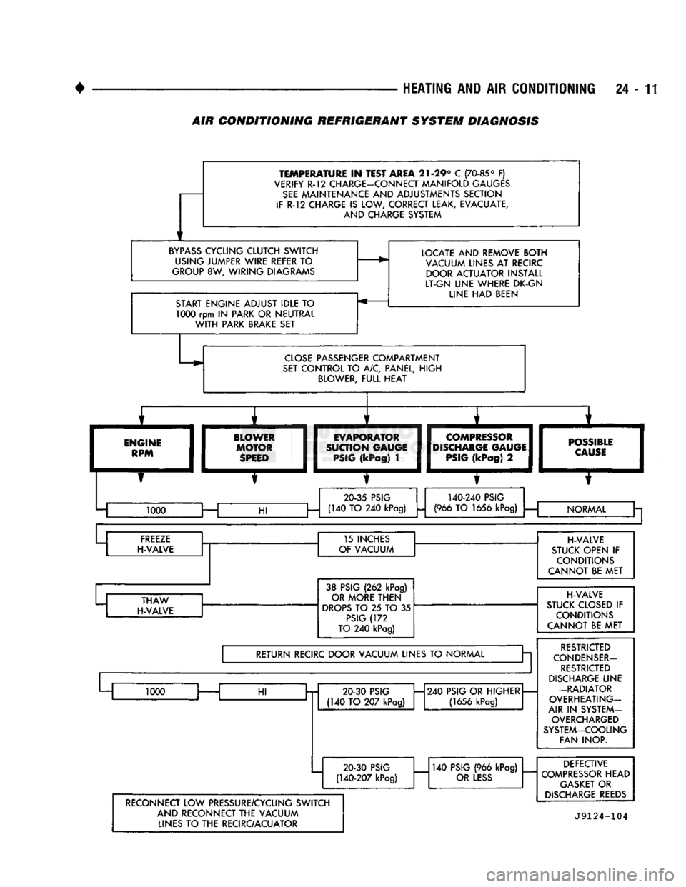
TEMPERATURE
IN
TEST AREA
21-29° C
(70-85°
F)
VERIFY R-12 CHARGE-CONNECT MANIFOLD GAUGES
SEE
MAINTENANCE AND ADJUSTMENTS SECTION
IF
R-12
CHARGE
IS
LOW, CORRECT LEAK, EVACUATE, AND CHARGE SYSTEM
BYPASS
CYCLING CLUTCH SWITCH USING JUMPER WIRE REFER
TO
GROUP
8W,
WIRING DIAGRAMS
START ENGINE ADJUST IDLE
TO 1000
rpm
IN
PARK OR NEUTRAL
WITH
PARK BRAKE SET LOCATE AND REMOVE BOTH
VACUUM LINES AT RECIRC DOOR ACTUATOR INSTALL
LT-GN LINE WHERE DK-GN LINE HAD BEEN
CLOSE
PASSENGER COMPARTMENT
SET
CONTROL TO A/C, PANEL, HIGH BLOWER, FULL HEAT
ENGINE
RPM BLOWER
MOTOR
SPEED
I
EVAPORATOR
I
SUCTION GAUGE
I
PSIG
(kPag)
1
COMPRESSOR
DISCHARGE
GAUGE
PSIG
(kPag)
2
—m
POSSIBLE
I
CAUSE
I
20-35
PSIG
140-240
PSIG
1000 —
HI
(140 TO 240
kPag)
(966
TO
1656
kPag)
i
— NORMAL
Cr a
FREEZE
H-VALVE 15 INCHES
OF VACUUM
THAW
H-VALVE 38 PSIG
(262
kPag)
OR MORE THEN
DROPS
TO 25 TO 35
PSIG
(172
TO
240
kPag)
RETURN RECIRC DOOR VACUUM LINES
TO
NORMAL a
1000
HI
20 30
PSIG
(140 TO 207
kPag)
H240
PSIG OR HIGHER
(1656
kPag)
20-30
PSIG
(140-207
kPag)
140
PSIG
(966
kPag)
OR
LESS
H-VALVE
STUCK OPEN
IF
CONDITIONS
CANNOT BE MET
H-VALVE
STUCK CLOSED
IF
CONDITIONS
CANNOT BE MET
RESTRICTED
CONDENSER-
RESTRICTED
DISCHARGE
LINE
-RADIATOR
OVERHEATING-
AIR
IN
SYSTEM- OVERCHARGED
SYSTEM-COOLING FAN INOP.
RECONNECT LOW PRESSURE/CYCLING SWITCH AND RECONNECT THE VACUUM LINES
TO
THE RECIRC/ACUATOR DEFECTIVE
COMPRESSOR
HEAD
GASKET
OR
DISCHARGE
REEDS
J9124-104
AIR
CONDITIONING REFRIGERANT SYSTEM DIAGNOSIS
Page 1449 of 1502
24-12
HEATING
AND AIR
CONDITIONING
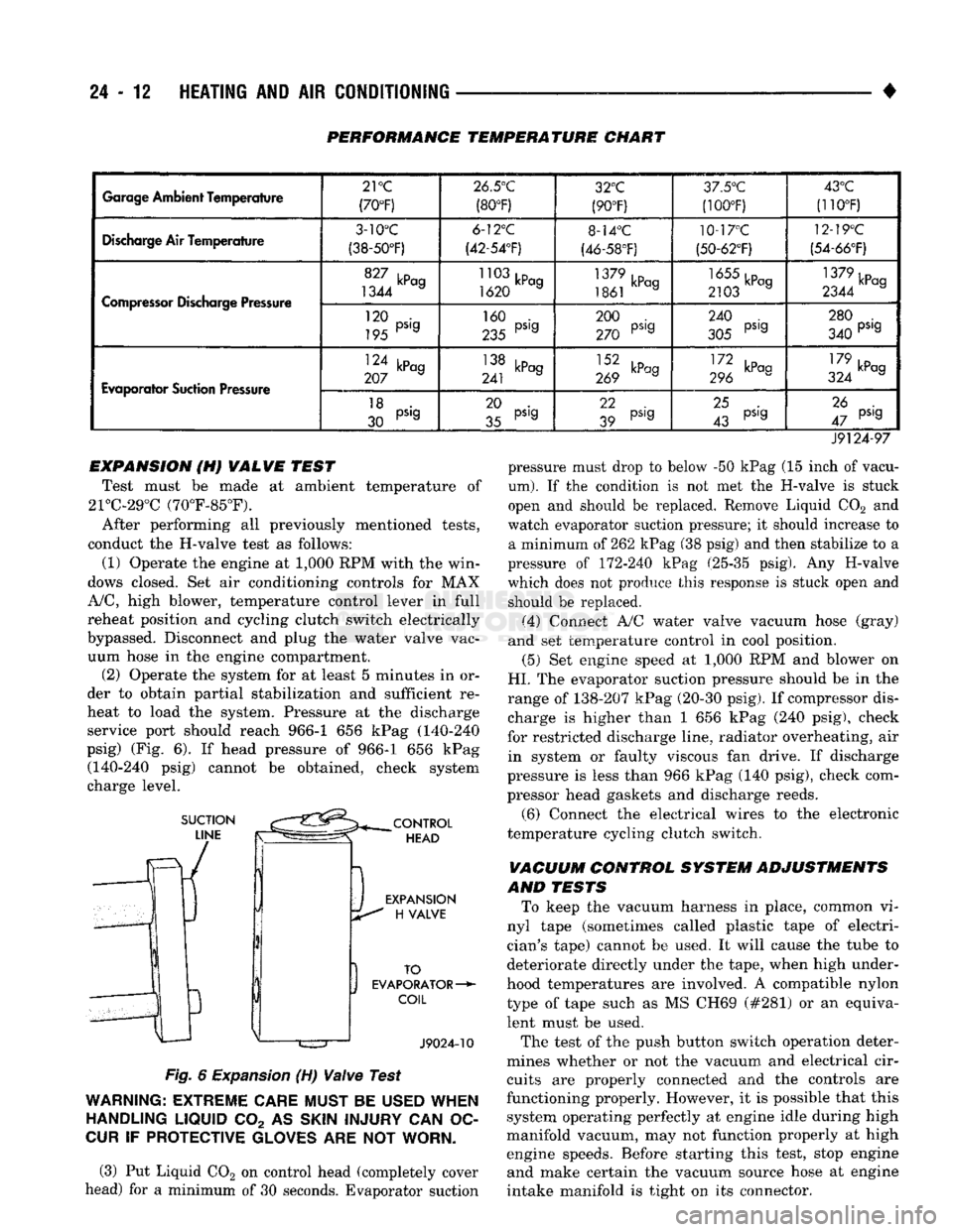
PERFORMANCE TEMPERATURE CHART
Garage
Ambient
Temperature
21
°C
(70°F) 26.5°C
(80°F) 32°C
(90°F) 3/.5°'J
(100T) 43°C
(110°F)
Discharge
Air Temperature
3-10°C
(38-50°F) 6-12°C
(42-54'F) 8-14°C
(46-58°F) 10-17°C
(50-62°F) 12-19°C
(54-66°F)
Compressor
Discharge Pressure
1344 a
1620 a
1861 kPag 2103 a 1379kPcg
2344 a
Compressor
Discharge Pressure
120 •
195 PS'9 160 .
235 PS'9 200 .
270 PS'9 240 .
305 PS'9 280 .
340 PS'9
Evaporator
Suction Pressure
124 kPag
207 a 138 kPag
241 J 269 kPag III kP°9
296 179 ,D
324 kPag
Evaporator
Suction Pressure
18 .
30 PS'9 20 .
35 pS'g 22
39 pS,g
25 .
43 pS'g 26 .
47 pS'9
J9124-97 pressure must drop to below -50 kPag (15 inch of vacu
um).
If the condition is not met the H-valve is stuck
open and should be replaced. Remove Liquid C02 and
watch evaporator suction pressure; it should increase to a minimum of 262 kPag (38 psig) and then stabilize to a
pressure of 172-240 kPag (25-35 psig). Any H-valve
which does not produce this response is stuck open and should be replaced.
(4) Connect A/C water valve vacuum hose (gray)
and set temperature control in cool position.
(5) Set engine speed at 1,000 RPM and blower on
HI.
The evaporator suction pressure should be in the
range of 138-207 kPag (20-30 psig). If compressor dis charge is higher than 1 656 kPag (240 psig), check
for restricted discharge line, radiator overheating, air in system or faulty viscous fan drive. If discharge
pressure is less than 966 kPag (140 psig), check com
pressor head gaskets and discharge reeds.
(6) Connect the electrical wires to the electronic
temperature cycling clutch switch.
VACUUM CONTROL SYSTEM ADJUSTMENTS
AND TESTS To keep the vacuum harness in place, common vi
nyl tape (sometimes called plastic tape of electri
cian's tape) cannot be used. It will cause the tube to
deteriorate directly under the tape, when high under
hood temperatures are involved. A compatible nylon type of tape such as MS CH69 (#281) or an equivalent must be used.
The test of the push button switch operation deter
mines whether or not the vacuum and electrical cir cuits are properly connected and the controls are
functioning properly. However, it is possible that this system operating perfectly at engine idle during high
manifold vacuum, may not function properly at high engine speeds. Before starting this test, stop engine and make certain the vacuum source hose at engine
intake manifold is tight on its connector.
EXPANSION (H) VALVE TEST
Test must be made at ambient temperature of
21°C-29°C (70°F-85°F).
After performing all previously mentioned tests,
conduct the H-valve test as follows:
(1) Operate the engine at 1,000 RPM with the win
dows closed. Set air conditioning controls for MAX
A/C,
high blower, temperature control lever in full
reheat position and cycling clutch switch electrically
bypassed. Disconnect and plug the water valve vac uum hose in the engine compartment. (2) Operate the system for at least 5 minutes in or
der to obtain partial stabilization and sufficient re
heat to load the system. Pressure at the discharge service port should reach 966-1 656 kPag (140-240
psig) (Fig. 6). If head pressure of 966-1 656 kPag (140-240 psig) cannot be obtained, check system
charge level.
Fig.
6
Expansion
(H)
Valve
Test
WARNING:
EXTREME
CARE
MUST
BE
USED
WHEN
HANDLING
LIQUID
C02 AS
SKIN
INJURY
CAN OC
CUR
IF
PROTECTIVE
GLOVES
ARE NOT
WORN.
(3) Put Liquid C02 on control head (completely cover
head) for a minimum of 30 seconds. Evaporator suction
Page 1451 of 1502
24 - 14
HEATING
AND AIR
CONDITIONING
•
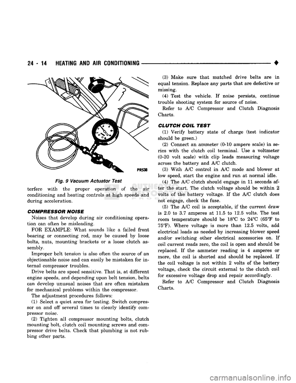
Fig.
9
Vacuum
Actuator Test terfere with the proper operation of the air
conditioning and heating controls at high speeds and
during acceleration.
COMPRESSOR NOISE Noises that develop during air conditioning opera
tion can often be misleading.
FOR EXAMPLE: What sounds like a failed front
bearing or connecting rod, may be caused by loose
bolts,
nuts, mounting brackets or a loose clutch as sembly.
Improper belt tension is also often the source of an
objectionable noise and can easily be mistaken for in
ternal compressor troubles.
Drive belts are speed sensitive. That is, at different
engine speeds, and depending upon belt tension, belts
can develop unusual noises that are often mistaken
for mechanical problems within the compressor.
The adjustment procedures follows: (1) Select a quiet area for testing. Switch compres
sor on and off several times to clearly identify com
pressor noise. (2) Tighten all compressor mounting bolts, clutch
mounting bolt, clutch coil mounting screws and com
pressor drive belts. Check that plumbing is not rub
bing other parts. (3) Make sure that matched drive belts are in
equal tension. Replace any parts that are defective or
missing.
(4) Test the vehicle. If noise persists, continue
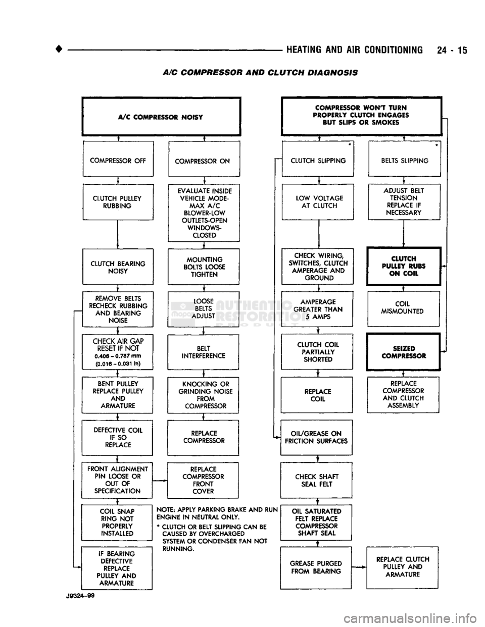
trouble shooting system for source of noise. Refer to A/C Compressor and Clutch Diagnosis
Charts.
CLUTCH COIL
TEST
(1) Verify battery state of charge (test indicator
should be green.)
(2) Connect an ammeter (0-10 ampere scale) in se
ries with the clutch coil terminal. Use a voltmeter (0-20 volt scale) with clip leads measuring voltage
across the battery and A/C clutch.
(3) With A/C control in A/C mode and blower at
low speed, start the engine and run at normal idle.
(4) The A/C clutch should engage in 11 seconds af
ter the start. The clutch voltage should be within 2
volts of the battery voltage. If the A/C clutch does not engage, check the fuse.
(5) The A/C coil is acceptable, if the current draw
is 2.0 to 3.7 amperes at 11.5 to 12.5 volts. The test
room temperature should be 18°C to 24°C (65°F to
75°F).
Where voltage is more than 12.5 volts, add
electrical loads as needed by increasing blower speed
and/or switching other electrical accessories on. If
coil current reads zero, the coil is open and should be
replaced. If the ammeter reading is 4 amperes or more, the coil is shorted and should be replaced. If
the coil voltage is not within 2 volts of the battery
voltage, check the circuit external to the clutch coil for excessive voltage drop and repair accordingly.
Refer to A/C Compressor and Clutch Diagnosis
Charts.
Page 1452 of 1502
HEATING
AND AIR
CONDITIONING
24 -
A/C COMPRESSOR AND CLUTCH DIAGNOSIS
A/C
COMPRESSOR NOISY
?
COMPRESSOR
OFF
COMPRESSOR
ON
I
CLUTCH PULLEY
RUBBING
EVALUATE INSIDE
VEHICLE MODE- MAX
A/C
BLOWER-LOW
OUTLETS-OPEN WINDOWS-
CLOSED
EVALUATE INSIDE
VEHICLE MODE- MAX
A/C
BLOWER-LOW
OUTLETS-OPEN WINDOWS-
CLOSED
CLUTCH BEARING NOISY
MOUNTING
BOLTS
LOOSE
TIGHTEN
•
REMOVE
BELTS
RECHECK
RUBBING AND BEARING
NOISE
LOOSE
BELTS
ADJUST
*
»
CHECK
AIR
GAP
RESET
IF
NOT
0.406
-
0.787
mm (0.016-0.031 In)
BELT
INTERFERENCE
• I
BENT PULLEY
REPLACE
PULLEY AND
ARMATURE KNOCKING
OR
GRINDING NOISE
FROM
COMPRESSOR
_ *
DEFECTIVE COIL IF
SO
REPLACE REPLACE
COMPRESSOR
FRONT
ALIGNMENT PIN LOOSE
OR
OUT
OF
SPECIFICATION
REPLACE
COMPRESSOR
FRONT
COVER
COMPRESSOR
WONT
TURN
PROPERLY
CLUTCH ENGAGES BUT SLIPS
OR
SMOKES
CLUTCH SLIPPING LOW VOLTAGE AT CLUTCH
CHECK
WIRING,
SWITCHES,
CLUTCH
AMPERAGE
AND
GROUND
I
AMPERAGE
GREATER
THAN
5
AMPS
CLUTCH COIL PARTIALLY SHORTED
REPLACE
COIL
OIL/GREASE
ON
FRICTION
SURFACES
CHECK
SHAFT
SEAL
FELT
COIL SNAP RING
NOT
PROPERLY
INSTALLED
IF BEARING DEFECTIVE
REPLACE
PULLEY
AND
ARMATURE NOTE: APPLY PARKING
BRAKE
AND RUN
ENGINE
IN
NEUTRAL ONLY.
*
CLUTCH OR BELT SUPPING CAN BE
CAUSED
BY OVERCHARGED
SYSTEM
OR CONDENSER FAN
NOT
RUNNING. OIL SATURATED
FELT
REPLACE
COMPRESSOR
SHAFT SEAL ADJUST BELT
TENSION
REPLACE
IF
NECESSARY
CLUTCH
PULLEY RUBS ON COIL
COIL
MISMOUNTED
SEIZED
COMPRESSOR
T
REPLACE
COMPRESSOR
AND CLUTCH
ASSEMBLY
GREASE
PURGED
FROM
BEARING
REPLACE
CLUTCH
PULLEY
AND
ARMATURE
GREASE
PURGED
FROM
BEARING
REPLACE
CLUTCH
PULLEY
AND
ARMATURE
J9324-99
Page 1453 of 1502
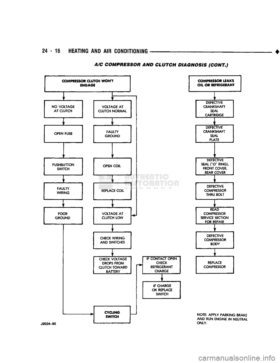
24 - 16 HEATING AND AIR CONDITIONING
A/C
COMPRESSOR AND CLUTCH DIAGNOSIS (CONT.)
COMPRESSOR
CLUTCH
WON'T
ENGAGE
f
f
NO
VOLTAGE
VOLTAGE
AT
AT CLUTCH CLUTCH
NORMAL
f t
OPEN FUSE FAULTY
GROUND
f
1
PUSHBUTTON SWITCH OPEN COIL
f
FAULTY
WIRING
REPLACE
COIL
f
r
POOR
VOLTAGE
AT
GROUND CLUTCH LOW
f
CHECK
WIRING
AND SWITCHES
f
CHECK
VOLTAGE
DROPS
FROM
CLUTCH TOWARD BATTERY
CYCLING SWITCH IF CONTACT OPEN
CHECK
REFRIGERANT
CHARGE
IF CHARGE
OK REPLACE SWITCH
COMPRESSOR
LEAKS
OIL OR REFRIGERANT
DEFECTIVE
CRANKSHAFT
SEAL
CARTRIDGE
DEFECTIVE
CRANKSHAFT
SEAL
PLATE
DEFECTIVE
SEAL
("O' RING),
FRONT
COVER,
REAR
COVER
DEFECTIVE
COMPRESSOR
THRU
BOLT
READ
COMPRESSOR
SERVICE
SECTION FOR REPAIR
DEFECTIVE
COMPRESSOR
BODY
REPLACE
COMPRESSOR
NOTE: APPLY PARKING BRAKE
AND RUN ENGINE
IN
NEUTRAL
ONLY.
Page 1457 of 1502
24
- 20
HEATING
AND AIR
CONDITIONING
• (3) Turn
3
refrigerant manifold valves completely
clockwise
to
puncture
the
cans
and
close
the
mani
fold valves.
(4) Purge
the air
from
the
charging line
by
loosen
ing
the
charging hose
at the
manifold gauge
set and
turn
one of the
refrigerant valves counterclockwise. When
the
refrigerant
gas
starts escaping from
the
loose connection, tighten
the
hose.
(5) Fully open
all 3
refrigerant manifold valves
and place
the
cans
of
refrigerant into
a pan
contain
ing 52°C (125°F) water.
The
water will warm
the
charging
can and aid in the
transfer
of the
charge
into
the
system.
(6) Start
the
engine
and
move
the
controls
to A/C
low blower position.
The electronic temperature cycling switch will pre
vent
the
clutch from engaging until refrigerant
is
added
to the
system.
If the
clutch does engage,
re
place
the
switch before proceeding
any
further. (7) Charge through
the
suction side
of the
system
by slowly opening
the
suction manifold valve. Adjust
the valve
as
necessary
so
charging pressure does
not
exceed
345
kPag
(50
psig). Maintain
the
temperature
of
the
water
in the pan by
adding warm water
as
necessary. (8) Adjust
the
engine speed
to a
fast idle
of
approx
imately
1,300 RPM.
(9) When
all 3
cans
of
refrigerant
are
completely
empty, close
the
manifold gauge
set
valves
and re
frigerant manifold valves. The maximum refrigerant charge
is 44 oz.
REFRIGERANT
LEAK REPAIR PROCEDURE
LOST CHARGE If
the
system
has
lost
all
charge
due to a
leak: (1) Evacuate
the
system.
(2) Charge
the
system with approximately
1
pound
of refrigerant. (3) Locate
all
leaks.
(4) Repair
all
leaks.
(5) Replace filter-drier bottle.
CAUTION:
Replacement
filter-drier
units
must
be
sealed
while
in
storage.
The
drier
used
in
these
units
absorbs
and
traps
moisture
quickly
upon
ex
posure
to the
atmosphere.
When
installing
a
drier,
have
all
tools
and
supplies ready
for
quick
reas
sembly
to
avoid keeping
the
system open
any
longer
than
necessary.
(6) Check system
oil
level. (7) Evacuate
and
charge
the
system.
LOW CHARGE If
the
system
has not
lost
all of its
refrigerant
charge; locate
and
repair
all
leaks.
If it is
necessary
to increase
the
system pressure
to
find
the
leak
(be
cause
of an
especially
low
charge),
add 230 g (1/2 lb)
of refrigerant.
If
there
has
been
a
significant
oil
loss,
check
the
system
oil
level.
If
leak repair
was
possible
without discharging system
and an oil
level check
was
not
necessary,
use
procedure
for
correcting
low
refrigerant level.
CORRECTING
LOW
REFRIGERANT LEVEL
Since
the
refrigeration system
is
completely sealed,
the refrigerant level will
not be low
unless there
is a
leak
in the
system. Before adding refrigerant where
the
cause
of a low
level
is not
known,
the
system should
be
tested
for
leaks.
Assuming that leaks have been corrected without
discharging
the
system, proceed with partial charge.
Install
and
connect manifold gauge
set.
(1) Close both manifold gauge
set
valves. Open
manifold gauge
set
needle valve.
(2) Connect
the
suction gauge test hose
to the
suc
tion service port
of the
compressor. Connect
the
dis charge gauge test hose
to the
discharge service port. (3) Connect
an end of
long test hose
to the
center
manifold outlet,
and
other
end to
refrigerant dispens ing manifold. (4) Close
the 2
dispensing manifold valves
and
open remaining dispensing manifold valve. Remove
protective
cap
from opened valve.
WARNING: NEVER
USE
THESE CANS
TO
CHARGE
INTO
THE
HIGH
PRESSURE SIDE
OF
THE
SYSTEM
(COMPRESSOR
DISCHARGE
PORT)
OR
INTO
A
SYSTEM
THAT
IS AT
HIGH
TEMPERATURE.
THE
HIGH
SYSTEM PRESSURES COULD
BE
TRANS
FERRED
INTO
THE
CHARGING
CAN
CAUSING
IT
TO EXPLODE.
(5) Screw
a can of R-12 to the
opened manifold
valve.
Be
sure gasket
is in
place
and in
good condi
tion. Tighten refrigerant
can and
manifold locking nut
to
ensure
a
good seal.
Do not
overtighten.
Tighten
to 9.5 N*m (7 ft. lbs.)
torque,
if
gasket
is in
good condition.
(6) Turn manifold valve (above
the
refrigerant
can)
completely clockwise
to
puncture
the can.
This closes
the valve
and
seals
the
refrigerant
in the can.
CAUTION:
Do not
heat refrigerant
12
above
52°C
(125°F).
(7) Place refrigerant
can in a
large
pan of
water
heated
to
52°C (125°F). Place
pan of
water containing
the refrigerant
can on an
accurate scale
so the
amount
of
refrigerant added
can be
weighed. Open
the refrigerant manifold valve.
(8) Purge
all air
from test hoses.
Air in the
system
will
be
trapped
in the
condenser causing abnormally
high discharge pressures
and
interfering with con densing
of the
refrigerant.
Page 1458 of 1502
•
HEATING
AND AIR
CONDITIONING
24 - 21 (a) Loosen both test hoses at the manifold gauge
set. Tighten the hoses as soon as the air is purged. (b) Loosen charging hose connection at manifold
gauge set. This will purge air from the charging
hose.
Tighten connection as soon as air is purged.
(9) With vehicle windows open and hood up, oper
ate engine at 1,300 RPM. (10) Place air conditioner control on A/C and place
the fan switch on high. (11) If necessary, block the condenser to maintain
a discharge pressure of 1 550-1 725 kPag (225-250
psig).
System must be charged through the evapora
tor suction service ports as follows:
(a) Slowly open the suction service gauge valve.
Meter flow of refrigerant by adjusting the suction service gauge valve so the pressure registered at
the suction service gauge does not exceed 345 kPag
COMPRESSOR
J
(50
psig). Keep refrigerant container upright.
(b) Add refrigerant gas until there is no foam visi
ble at the sight glass. As soon as all foam clears, note the weight registered on the refrigerant scale.
(c) Watch the refrigerant weighing scale and add
437 g (14 oz.) of refrigerant (equivalent to 1 can).
(d) Close the suction gauge valve.
CAUTION:
TOO
much
refrigerant
in the
system
can
cause
abnormally high discharge pressures. Care
must
be
used
so the
exact recommended amount
of
refrigerant
is
added
after
foam clears
in the
sight
glass.
(e) Close dispensing manifold valve. Remove test
hoses and adapters from the service ports of com
pressor and install protective caps at service ports.
RVICE (SD-709)
INDEX
page
Compressor
21
Compressor
Shaft Seal
.................... 25
The A/C system uses a 7 piston design Sanden SD-
709 compressor. Designated the SD-709, the compres
sor is mounted on the front right side of the engine
and is driven by a serpentine belt.
System lubrication is provided by 135cc ±15cc (4.6
cu. in. ±0.5 cu. in.) of 500 viscosity refrigerant oil.
The clutch used on the compressor consists of 3 ba
sic components:
(1) The pulley.
(2) The front plate. (3) The field coil.
The pulley and field coil are attached to the front
head of the compressor with snap rings. The hub is keyed to the compressor shaft and is retained on the
shaft with a self-locking nut. Special service tools are
required to remove and install the clutch plate on
the compressor shaft.
COMPRESSOR
REMOVAL
(1) Disconnect the negative cable from the battery.
(2) Disconnect the clutch lead wire.
(3) Remove the discharge and inlet (suction) ser
vice valves from the compressor. Plug or tape all the
openings.
(4) Refer to Group 7, Cooling System and remove
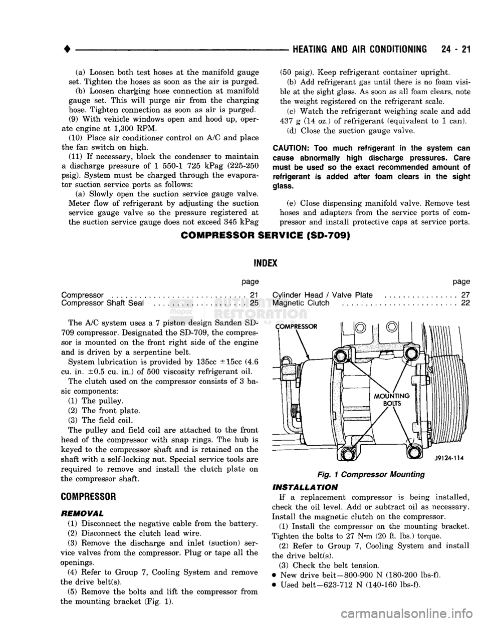
the drive belt(s). (5) Remove the bolts and lift the compressor from
the mounting bracket (Fig. 1).
page
Cylinder Head
/
Valve Plate
27
Magnetic
Clutch
22
Fig.
1
Compressor
Mounting
INSTALLATION
If a replacement compressor is being installed,
check the oil level. Add or subtract oil as necessary.
Install the magnetic clutch on the compressor.
(1) Install the compressor on the mounting bracket.
Tighten the bolts to 27 N*m (20 ft. lbs.) torque.
(2) Refer to Group 7, Cooling System and install
the drive belt(s).
(3) Check the belt tension.
@ New drive belt-800-900 N (180-200 lbs-f).
• Used belt-623-712 N (140-160 lbs-f).
Page 1459 of 1502
24 - 22
HEATING
AND AIR
CONDITIONING
•
(4)
Remove the tape or plastic plugs from all the
suction and discharge openings and install the ser
vice valves on the compressor.
(5)
Connect the clutch lead wire.
(6) Connect the negative cable to the battery.
(7)
Evacuate, charge and test the system for leaks.
MAGNETIC
CLUTCH
The magnetic clutch consists of a stationary electro
magnetic coil and a rotating pulley and plate assembly. The electromagnetic coil is retained on the com
pressor with a snap ring and is dimpled to maintain its position. The pulley and plate assembly are mounted on the
compressor shaft. When the compressor is not in operation, the pul
ley free wheels on the clutch hub bearing. When the
coil is energized the plate is magnetically engaged
with the pulley and turns the compressor shaft.
J8924-18
Fig.
3
Clutch
Front
Plate
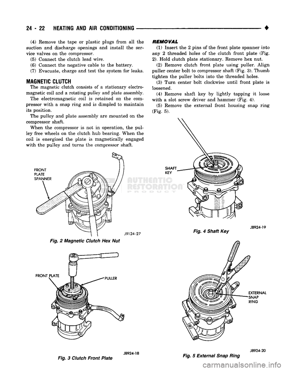
REMOVAL
(1) Insert the 2 pins of the front plate spanner into
any 2 threaded holes of the clutch front plate (Fig.
2).
Hold clutch plate stationary. Remove hex nut. (2) Remove clutch front plate using puller. Align
puller center bolt to compressor shaft (Fig. 3). Thumb tighten the puller bolts into the threaded holes. (3) Turn center bolt clockwise until front plate is
loosened. (4) Remove shaft key by lightly tapping it loose
with a slot screw driver and hammer (Fig. 4).
(5)
Remove the external front housing snap ring
(Fig. 5).
J8924-19
Fig.
4 Shaft Key
J8924-20
Fig.
5 External
Snap Ring