1993 DODGE TRUCK radiator cap
[x] Cancel search: radiator capPage 652 of 1502
5.2L
ENGINE
9 - 47
S.2L ENGINE
SERVICE
PROCEDURES
INDEX
page
Camshaft
. , . 61
Crankshaft
68
Crankshaft Main Bearings
69
Crankshaft Rear
Oil
Seals
...... ........
70
Cylinder Block ...........................
71
Cylinder Head Cover
. . . . 51
Cylinder Heads
52
Distributor
62
Engine
Assembly
. 50
Engine
Front Mounts
47
Engine
Rear Mount ...............
48
Front Crankshaft
Oil
Seal Replacement
. . 61
GENERAL
INFORMATION
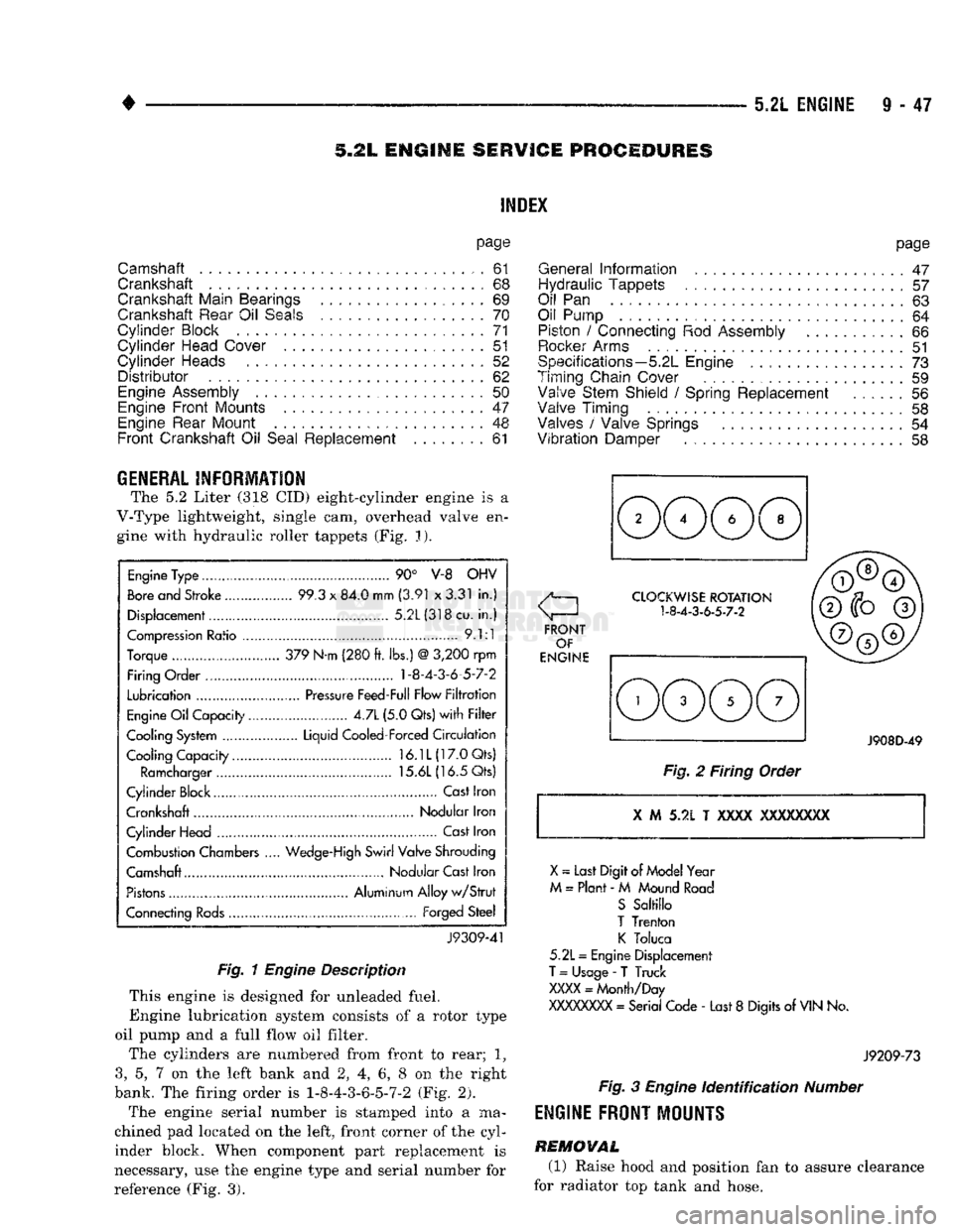
The 5.2 Liter (318 CID) eight-cylinder engine is a
V-Type lightweight, single cam, overhead valve en gine with hydraulic roller tappets (Fig. J).
Engine
Type ....
90° V-8 OHV
Bore
and Stroke .....
99.3
x
84.0 mm
(3.91
x
3.31
in.)
Displacement................
5.2L(318cu.
in.)
Compression
Ratio ....... .
9.1:1
Torque .. 379 N-m (280
ft.
lbs.)
@
3,200
rpm
Firing Order .... 1-8-4-3-6-5-7-2
Lubrication
.......
Pressure
Feed-Full Flow
Filtration
Engine
Oil
Capacity......
4.7L
(5.0 Qts)
with Filter
Cooling System ...... Liquid Cooled-Forced
Circulation
Cooling Capacity..........
16.1L(17.0Qts)
Ramcharger
15.6L
(16.5 Qts)
Cylinder Block
,
Cast
Iron
Crankshaft Nodular Iron
Cylinder Head ..............
Cast
Iron
Combustion Chambers
..
Wedge-High
Swirl Valve Shrouding
Camshaft Nodular Cast Iron
Pistons
Aluminum Alloy
w/Strut
Connecting
Rods...........
Forged
Steel
J9309-41
Fig. 1
Engine
Description
This engine is designed for unleaded fuel.
Engine lubrication system consists of a rotor type
oil pump and a full flow oil filter.
The cylinders are numbered from front to rear; 1?
3,
5, 7 on the left bank and 2, 4, 6, 8 on the right
bank. The firing order is 1-8-4-3-6-5-7-2 (Fig. 2).
The engine serial number is stamped into a ma
chined pad located on the left, front corner of the cyl
inder block. When component part replacement is
necessary, use the engine type and serial number for
reference (Fig. 3).
page
General
Information
.......................
47
Hydraulic Tappets
57
Oil
Pan . 63
Oil Pump
. 64
Piston
/
Connecting
Rod
Assembly
66
Rocker
Arms
51
Specifications—5.2L Engine
73
Timing Chain Cover ................
59
Valve Stem Shield
/
Spring Replacement
56
Valve Timing
. 58
Valves
/
Valve Springs
54
Vibration
Damper
. . 58
J908D-49
Fig.
2 Firing Order
X
M 5.2L T
XXXX
XXXXXXXX
X
~
Last Digit of
Model
Year
M
=
Plant
- M
Mound
Road
S
Saltillo
T
Trenton
K
Toluca
5.2L
=
Engine Displacement
T
=
Usage
-
T Truck
XXXX
=
Month/Day
XXXXXXXX
=
Serial Code
-
Last
8
Digits
of
VIN
No.
J9209-73
Fig.
3
Engine
Identification
Number
ENGINE
FRONT
MOUNTS
REMOVAL
(1) Raise hood and position fan to assure clearance
for radiator top tank and hose.
Page 655 of 1502
TRANSFER
CASE
TRANSFER
CASE
ENGINE
REAR
SUPPORT PLATE
EXTENSION
ASSEMBLY
TRANSMISSION
SUPPORT
SPACER
SPACER
UPPER
INSULATOR
INSULATOR
MOUNTING
PLATE
LOWER
INSULATOR
fT^RAIL
J9109-244
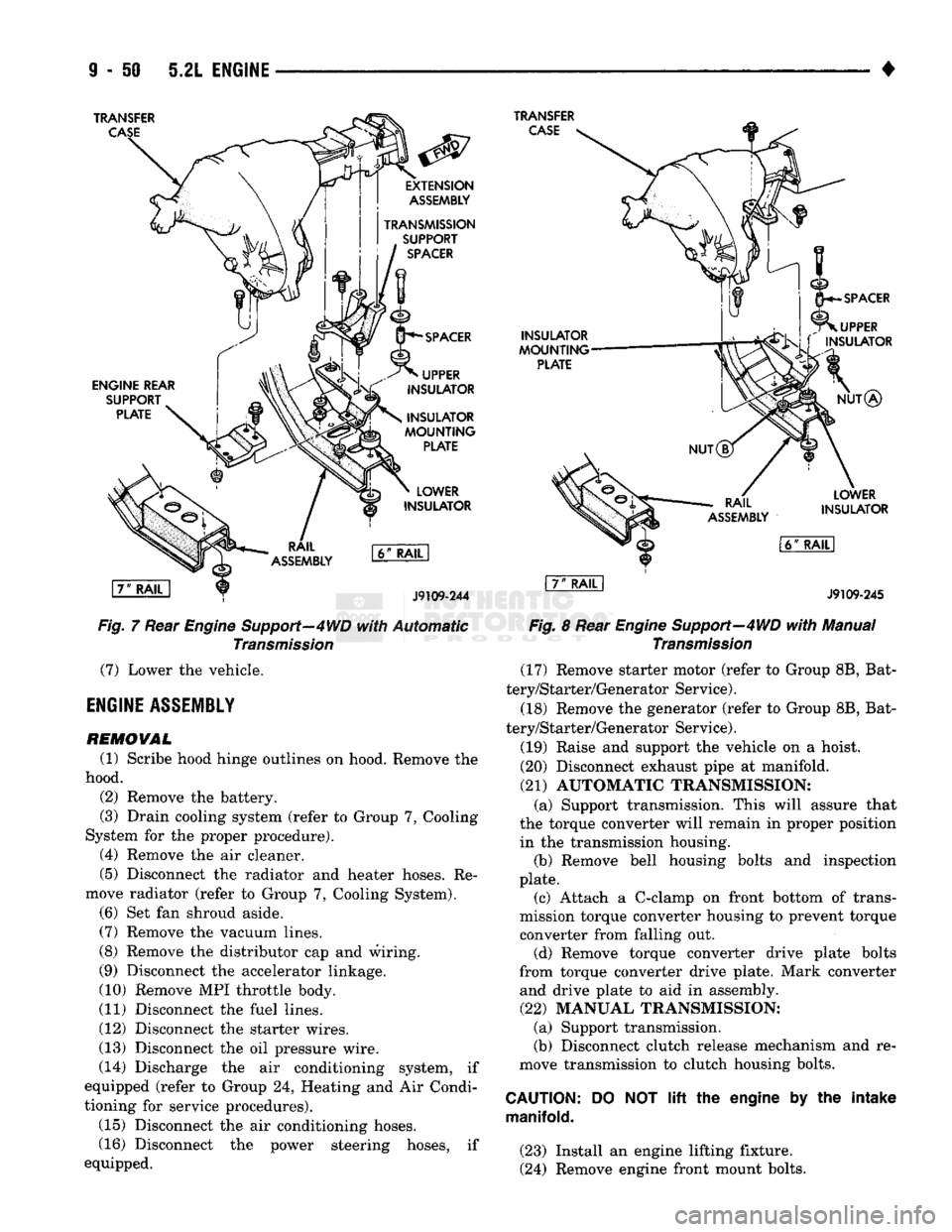
Fig,
7 Rear Engine Support—4WD
with
Automatic
Transmission
(7)
Lower the vehicle.
ENGINE
ASSEMBLY
REMOVAL
(1) Scribe hood hinge outlines on hood. Remove the
hood. (2) Remove the battery.
(3) Drain cooling system (refer to Group 7, Cooling
System for the proper procedure). (4) Remove the air cleaner.
(5) Disconnect the radiator and heater hoses. Re
move radiator (refer to Group 7, Cooling System). (6) Set fan shroud aside.
(7)
Remove the vacuum lines.
(8) Remove the distributor cap and wiring.
(9) Disconnect the accelerator linkage.
(10) Remove MPI throttle body.
(11) Disconnect the fuel lines.
(12) Disconnect the starter wires.
(13) Disconnect the oil pressure wire.
(14) Discharge the air conditioning system, if
equipped (refer to Group 24, Heating and Air Condi
tioning for service procedures).
(15) Disconnect the air conditioning hoses.
(16) Disconnect the power steering hoses, if
equipped.
INSULATOR
MOUNTING
PLATE
SPACER
UPPER
L\ f
INSULATOR
NUT®
RAIL
ASSEMBLY
LOWER
INSULATOR
l6ff
RAIL
I
J9109-245
Fig.
8 Rear
Engine
Support—4WD
with
Manual
Transmission
(17) Remove starter motor (refer to Group 8B, Bat
tery/Starter/Generator Service).
(18) Remove the generator (refer to Group 8B, Bat
tery/Starter/Generator Service).
(19) Raise and support the vehicle on a hoist.
(20) Disconnect exhaust pipe at manifold.
(21)
AUTOMATIC TRANSMISSION: (a) Support transmission. This will assure that
the torque converter will remain in proper position in the transmission housing. (b) Remove bell housing bolts and inspection
plate. (c) Attach a C-clamp on front bottom of trans
mission torque converter housing to prevent torque
converter from falling out. (d) Remove torque converter drive plate bolts
from torque converter drive plate. Mark converter and drive plate to aid in assembly.
(22)
MANUAL TRANSMISSION; (a) Support transmission.
(b) Disconnect clutch release mechanism and re
move transmission to clutch housing bolts.
CAUTION:
manifold.
DO
NOT lift the
engine
by the
intake
(23) Install an engine lifting fixture.
(24) Remove engine front mount bolts.
Page 656 of 1502
•
5.2L
ENGINE
9 - 51 (25) Lower the vehicle.
(26) On automatic transmission vehicles, discon
nect the engine from the torque converter drive
plate. On manual transmission vehicles, move engine forward until drive pinion shaft clears the clutch
disc.
Remove engine from engine compartment.
(27) Install engine assembly on engine repair
stand.
INSTALLATION
(1) Remove engine from the repair stand and posi
tion in the engine compartment.
(2) Install an engine support fixture.
(3) Raise and support the vehicle on a hoist.
(4) AUTOMATIC TRANSMISSION: (a) Position the torque converter and drive plate.
Install torque converter drive plate bolts. Tighten
the bolts to 31 N-m (270 in. lbs.) torque.
(b) Install the engine front mounts.
(c) Install bell housing bolts. Tighten the bolts to
41 N-m (30 ft. lbs.) torque.
(d) Remove C-clamp.
(e) Install the inspection plate.
(5) MANUAL TRANSMISSION: (a) Position the drive pinion shaft to the clutch
disc.
(b) Connect the clutch release mechanism and
install the transmission to clutch bolts. Tighten the
bolts to 68 N-m (50 ft. lbs.) torque.
(c) Install the engine front mounts.
(6) Remove transmission support.
(7) Install exhaust pipe to manifold. (8) Lower the vehicle.
(9) Remove engine lifting fixture. (10) Install the generator (refer to Group 8B, Bat
tery/Starter/ Generator Service). (11) Install the starter motor (refer to Group 8B,
Battery/Starter/Generator Service). (12) Connect power steering hoses, if so equipped.
(13) Connect air conditioning hoses.
(14) Evacuate and charge the air conditioning sys
tem, if equipped (refer to Group 24, Heater and Air Conditioning for service procedures).
(15) Using a new gasket, install MPI throttle body.
Tighten the throttle body bolts to 23 N-m (200 in. lbs.) torque. (16) Connect the accelerator linkage.
(17) Connect the starter wires.
(18) Connect the oil pressure wire. (19) Install the distributor cap and wiring.
(20) Connect the vacuum lines.
(21) Connect the fuel lines,
(22) Install the radiator (refer to Group 7, Cooling
System). Connect the radiator hoses and heater
hoses.
(23) Install fan shroud in position.
(24) Fill cooling system (refer to Group 7, Cooling
System for the proper procedure). (25) Install the air cleaner.
(26) Install the battery. (27) Warm engine and adjust.
(28) Install hood and line up with the scribe
marks. (29) Road test vehicle.
CYLIiiER
HEAD
COVER
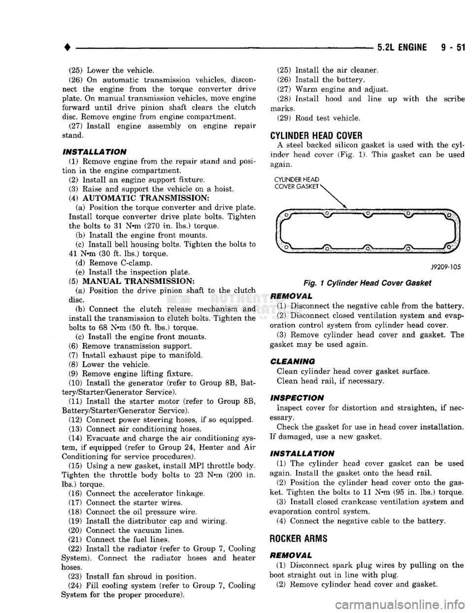
A steel backed silicon gasket is used with the cyl
inder head cover (Fig. 1). This gasket can be used
again.
CYLINDER HEAD
J9209-105
Fig.
1 Cylinder Head
Cover
Gasket
REMOVAL
(1) Disconnect the negative cable from the battery.
(2) Disconnect closed ventilation system and evap
oration control system from cylinder head cover.
(3) Remove cylinder head cover and gasket. The
gasket may be used again.
CLEANING
Clean cylinder head cover gasket surface. Clean head rail, if necessary.
INSPECTION
Inspect cover for distortion and straighten, if nec
essary.
Check the gasket for use in head cover installation.
If damaged, use a new gasket.
INSTALLATION
(1) The cylinder head cover gasket can be used
again. Install the gasket onto the head rail.
(2) Position the cylinder head cover onto the gas
ket. Tighten the bolts to 11 N-m (95 in. lbs.) torque.
(3) Install closed crankcase ventilation system and
evaporation control system.
(4) Connect the negative cable to the battery.
ROCKER ARMS
REMOVAL
(1) Disconnect spark plug wires by pulling on the
boot straight out in line with plug. (2) Remove cylinder head cover and gasket.
Page 682 of 1502
5.9L
ENGINE SERVICE PROCEDURES
INDEX
page
Camshaft
91
Crankshaft
98
Crankshaft Main Bearings
99
Crankshaft Rear
Oil
Seals
100
Cylinder
Block
101
Cylinder
Head Cover
81
Cylinder
Heads
82
Distributor
92
Engine Assembly
80
Engine
Front
Mounts
77
Engine Rear Mount
78
Front
Crankshaft
Oil
Seal Replacement
91
page
General
Information
77
Hydraulic
Tappets
87
Oil
Pan 93
Oil Pump
. 94
Piston
/
Connecting
Rod
Assembly
96
Rocker Arms
81
Specifications—5.9L
Engine
103
Timing
Chain Cover
89
Valve Stem Shield
/
Spring Replacement
86
Valve
Timing
. 88
Valves
/
Valve Springs
84
Vibration
Damper
88
GENERAL
INFORMATION
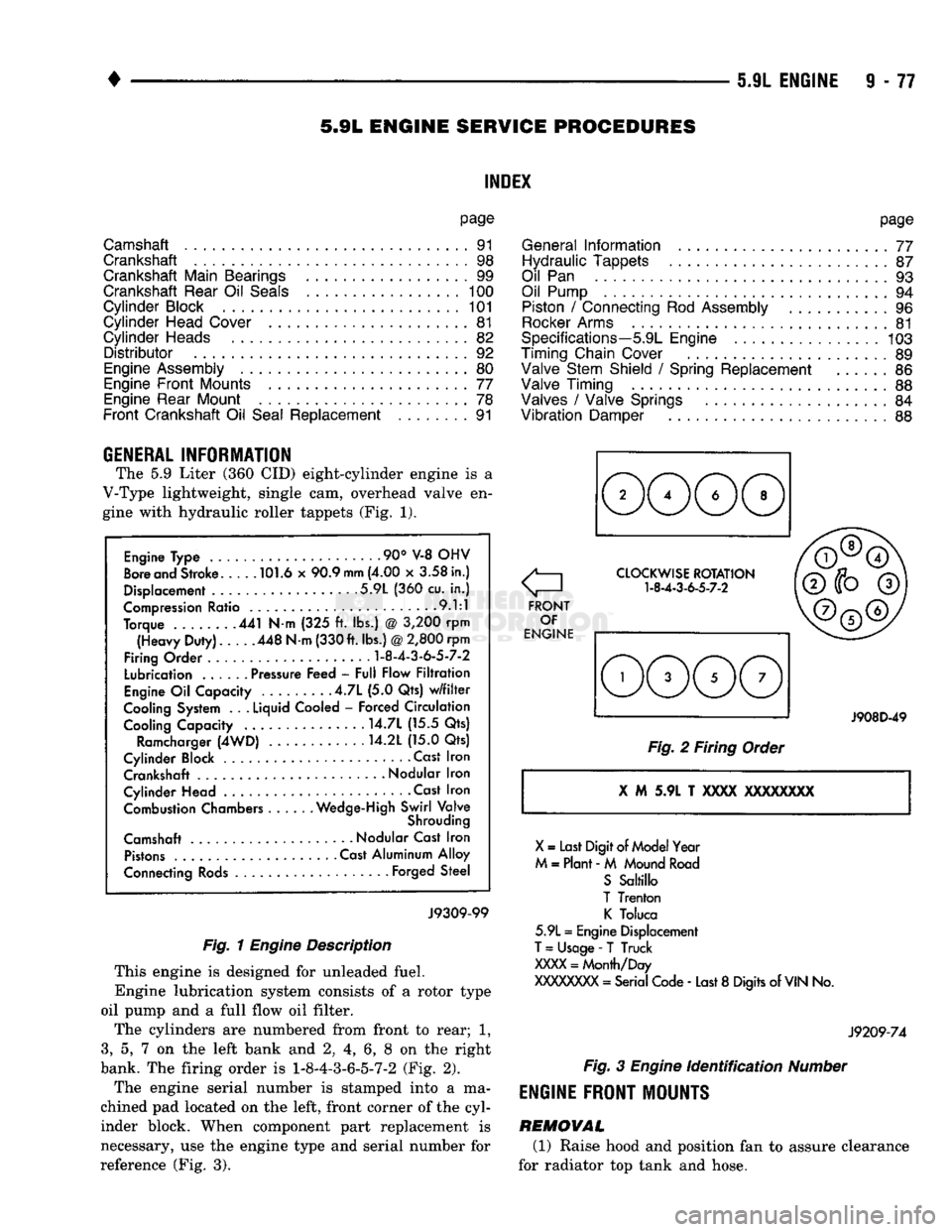
The 5.9 Liter (360 CID) eight-cylinder engine is a
V-Type lightweight, single cam, overhead valve en
gine with hydraulic roller tappets (Fig. 1).
Engine Type .90° V-8 OHV
Bore and Stroke 101.6 x 90.9
mm
(4.00 x 3.58 in.)
Displacement 5.9L (360 cu. in.)
Compression Ratio 9.1:1
Torque 441 N-m (325 ft. lbs.) @ 3,200 rpm (Heavy Duty). 448 N-m (330 ft. lbs.)
@
2,800 rpm
Firing Order
1-8-4-3-6-5-7-2
Lubrication ...... Pressure Feed - Full Flow Filtration
Engine Oil Capacity .4.7L (5.0 Qts) w/filter
Cooling System . .
.
Liquid Cooled - Forced Circulation Cooling Capacity ..... . . 14.7L (15.5 Qts)
Ramcharger (4WD) 14.2L (15.0 Qts)
Cylinder Block Cast Iron Crankshaft
-
Nodular Iron
Cylinder Head • . Cast Iron Combustion Chambers Wedge-High Swirl Valve
Shrouding
Camshaft Nodular Cast Iron Pistons Cast Aluminum Alloy
Connecting Rods Forged Steel
J9309-99
Fig. 1
Engine
Description
This engine is designed for unleaded fuel.
Engine lubrication system consists of a rotor type
oil pump and a full flow oil filter.
The cylinders are numbered from front to rear; 1,
3,
5, 7 on the left bank and 2, 4, 6, 8 on the right
bank. The firing order is
1-8-4-3-6-5-7-2
(Fig. 2).
The engine serial number is stamped into a ma
chined pad located on the left, front corner of the cyl
inder block. When component part replacement is
necessary, use the engine type and serial number for
reference (Fig. 3).
o
FRONT OF
ENGINE CLOCKWISE ROTATION
1-8-4-3-6-5-7-2
J908D-49
Fig. 2 Firing Order
X
M 5.9L T
XXXX
XXXXXXXX
X
= Last Digit of Model Year
M = Plant - M Mound Road S Saltillo
T Trenton K Toluca
5.9L = Engine Displacement
T
= Usage -
T
Truck
XXXX
= Month/Day
XXXXXXXX
= Serial Code - Last 8 Digits of
VIN
No.
J9209-74
Fig.
3
Engine
identification
Number
ENGINE
FRONT MOUNTS
REMOVAL (1) Raise hood and position fan to assure clearance
for radiator top tank and hose.
Page 685 of 1502
9
- 80 5.9L
ENGINE
•
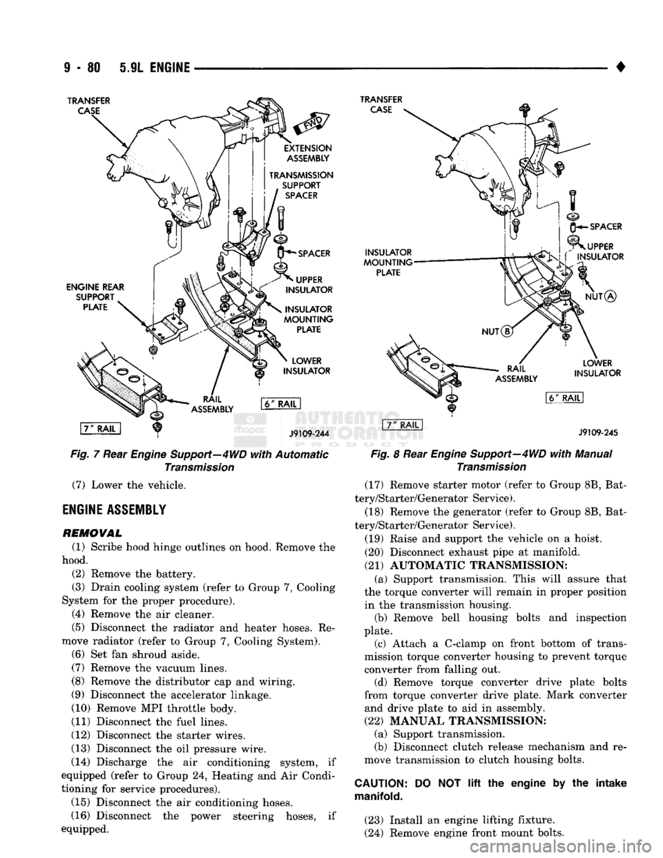
TRANSFER
CASE
TRANSFER
CASE
ENGINE REAR
SUPPORT
PLATE
INSULATOR
MOUNTING
PLATE
LOWER
INSULATOR
\7"
RAIL
1
J9109-244
Fig.
7 Rear
Engine
Support—4WD
with
Automatic
Transmission
(7) Lower the vehicle.
ENGINE
ASSEMBLY
REMOVAL
(1) Scribe hood hinge outlines on hood. Remove the
hood. (2) Remove the battery.
(3) Drain cooling system (refer to Group 7, Cooling
System for the proper procedure). (4) Remove the air cleaner.
(5) Disconnect the radiator and heater hoses. Re
move radiator (refer to Group 7, Cooling System). (6) Set fan shroud aside.
(7) Remove the vacuum lines.
(8) Remove the distributor cap and wiring.
(9) Disconnect the accelerator linkage.
(10) Remove MPI throttle body.
(11) Disconnect the fuel lines.
(12) Disconnect the starter wires.
(13) Disconnect the oil pressure wire.
(14) Discharge the air conditioning system, if
equipped (refer to Group 24, Heating and Air Condi
tioning for service procedures).
(15) Disconnect the air conditioning hoses.
(16) Disconnect the power steering hoses, if
equipped.
INSULATOR
MOUNTING
PLATE
SPACER
UPPER
INSULATOR
NUT®
LOWER
INSULATOR
J9109-245
Fig.
8 Rear
Engine
Support—4WD
with
Manual
Transmission
(17) Remove starter motor (refer to Group 8B, Bat
tery/Starter/Generator Service).
(18) Remove the generator (refer to Group 8B, Bat
tery/Starter/Generator Service).
(19) Raise and support the vehicle on a hoist.
(20) Disconnect exhaust pipe at manifold.
(21) AUTOMATIC TRANSMISSION: (a) Support transmission. This will assure that
the torque converter will remain in proper position in the transmission housing. (b) Remove bell housing bolts and inspection
plate. (c) Attach a C-clamp on front bottom of trans
mission torque converter housing to prevent torque converter from falling out. (d) Remove torque converter drive plate bolts
from torque converter drive plate. Mark converter and drive plate to aid in assembly.
(22) MANUAL TRANSMISSION; (a) Support transmission.
(b) Disconnect clutch release mechanism and re
move transmission to clutch housing bolts.
CAUTION:
manifold.
DO
NOT
lift
the engine by the intake
(23) Install an engine lifting fixture.
(24) Remove engine front mount bolts.
Page 686 of 1502
•
5.9L ENGINE
9-81 (25) Lower the vehicle.
(26) On automatic transmission vehicles, discon
nect the engine from the torque converter drive
plate. On manual transmission vehicles, move engine forward until drive pinion shaft clears the clutch
disc.
Remove engine from engine compartment.
(27) Install engine assembly on engine repair
stand.
INSTALLATION (1) Remove engine from the repair stand and posi
tion in the engine compartment.
(2) Install an engine support fixture.
(3) Raise and support the vehicle on a hoist.
(4)
AUTOMATIC TRANSMISSION: (a) Position the torque converter and drive plate.
Install torque converter drive plate bolts. Tighten
the bolts to 31 Nnn (270 in. lbs.) torque.
(b) Install the engine front mounts.
(c) Install bell housing bolts. Tighten the bolts to
41 Nnn (30 ft. lbs.) torque.
(d) Remove C-clamp.
(e) Install the inspection plate.
(5)
MANUAL TRANSMISSION: (a) Position the drive pinion shaft to the clutch
disc.
(b) Connect the clutch release mechanism and
install the transmission to clutch bolts. Tighten the
bolts to 68 Nnn (50 ft. lbs.) torque.
(c) Install the engine front mounts.
(6) Remove transmission support.
(7) Install exhaust pipe to manifold. (8) Lower the vehicle.
(9) Remove engine lifting fixture.
(10) Install the generator (refer to Group 8B, Bat
tery/Starter/Generator Service). (11) Install the starter motor (refer to Group 8B,
Battery/Starter/Generator Service).
(12) Connect power steering hoses, if so equipped.
(13) Connect air conditioning hoses.
(14) Evacuate and charge the air conditioning sys
tem, if equipped (refer to Group 24, Heater and Air Conditioning for service procedures).
(15) Using a new gasket, install MPI throttle body.
Tighten the throttle body bolts to 23 Nnn (200 in. lbs.) torque.
(16) Connect the accelerator linkage. (17) Connect the starter wires.
(18) Connect the oil pressure wire.
(19) Install the distributor cap and wiring.
(20) Connect the vacuum lines.
(21) Connect the fuel lines.
(22) Install the radiator (refer to Group 7, Cooling
System). Connect the radiator hoses and heater
hoses.
(23) Install fan shroud in position.
(24) Fill cooling system (refer to Group 7, Cooling
System for the proper procedure). (25) Install the air cleaner.
(26) Install the battery.
(27) Warm engine and adjust.
(28) Install hood and line up with the scribe
marks. (29) Road test vehicle.
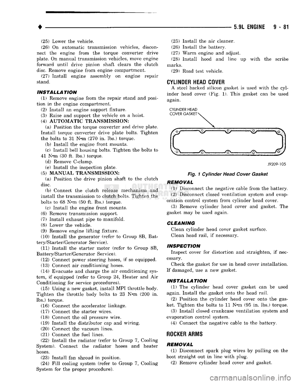
CYLINDER HEAD COVER
A steel backed silicon gasket is used with the cyl
inder head cover (Fig. 1). This gasket can be used
again.
CYLINDER HEAD
J9209-105
Fig.
1 Cylinder Head
Cover
Gasket
REMOVAL (1) Disconnect the negative cable from the battery.
(2) Disconnect closed ventilation system and evap
oration control system from cylinder head cover.
(3) Remove cylinder head cover and gasket. The
gasket may be used again.
CLEANING
Clean cylinder head cover gasket surface.
Clean head rail, if necessary.
INSPECTION Inspect cover for distortion and straighten, if nec
essary.
Check the gasket for use in head cover installation.
If damaged, use a new gasket.
INSTALLATION (1) The cylinder head cover gasket can be used
again. Install the gasket onto the head rail.
(2) Position the cylinder head cover onto the gas
ket. Tighten the bolts to 11 Nnn (95 in. lbs.) torque. (3) Install closed crankcase ventilation system and
evaporation control system.
(4) Connect the negative cable to the battery.
ROCKER
ARMS
REMOVAL (1) Disconnect spark plug wires by pulling on the
boot straight out in line with plug.
(2) Remove cylinder head cover and gasket.
Page 712 of 1502
•
5.9L
(DIESEL)
ENGINE
9 -
107
5.9L
(DIESEL)
ENGINE
SERVICE
PROCEDURES
INDEX
page
Camshaft
127
Crankshaft
138
Cylinder
Block
129
Cylinder
Head
113
Engine
Assembly
. 109
Engine
Front
Mounts
(Insulators
/
Brackets)
... 107
Engine
Rear Support
108
Gear
Housing
/
Cover
122
General
Information
107
Oil Cooler Element
/
Gasket
. 149
Oil
Filter
148
page
Oil
Filter
Bypass
Valve
. 148
Oil Pan
/
Suction Tube
146
Oil Pressure Regulator Valve
/
Spring
148
Oil Pump
146
Piston
/
Connecting
Rod
Assembly
134
Rocker
Levers
/
Push
Rods
112
Specifications—5.9L Diesel Engines
151
Tappet
125
Timing
Pin
123
Valve Clearance
Adjustment
...............
121
Valves
and
Valve Springs
116
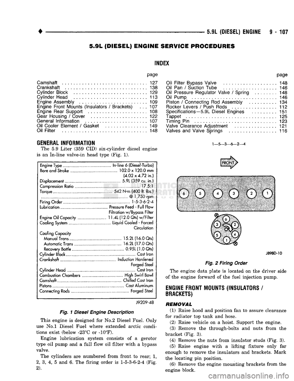
GENERAL INFORMATION The
5.9
Liter
(359 CID)
six-cylinder diesel engine
is
an
In-line valve-in head type
(Fig. 1).
Fig.
1
Diesel
Engine
Description
This engine
is
designed
for No.2
Diesel Fuel. Only
use
No.l
Diesel Fuel where extended arctic condi
tions exist (below -23°C
or -10°F).
Engine lubrication system consists
of a
gerotor
type
oil
pump
and a
full flow
oil
filter with
a
bypass valve.
The cylinders
are
numbered from front
to
rear;
1,
2,
3, 4, 5 and 6. The
firing order
is
1-5-3-6-2-4
(Fig.
2).
J898D-10
Fig.
2
Firing Order
The engine data plate
is
located
on the
driver side
of
the
engine forward
of the
fuel injection pump.
ENGINE FRONT MOUNTS (INSULATORS
/
BRACKETS)
REMOVAL (1) Raise hood
and
position
fan to
assure clearance
for radiator
top
tank
and
hose.
(2) Raise vehicle
on a
hoist. Support
the
engine.
(3) Remove
the
through-bolts
and
nuts from
the
bracket
(Fig. 3).
(4) Remove
the
nuts from insulator studs
(Fig. 3).
(5) Raise engine with
a
lifting fixture only
far
enough
to
remove
the
insulators
and
brackets. Mark
the locating
pin
position.
(6) Remove
the
engine mounting brackets from
the
engine block.
Engine Type
In-line
6
(Diesel-Turbo)
Bore and Stroke 102.0 x 120.0 mm
(4.02x4.72 in.)
Displacement 5.9L (359 cu.
in.)
Compression Ratio 17.5:1
Torque 542 N-m (400 ft. lbs.)
@
1,750 rpm
Firing Order
1-5-3-6-2-4
Lubrication Pressure Feed - Full Flow
Filtration w/Bypass Filter
Engine Oil Capacity
11.4L
(12.0 Qts) w/Filter
Cooling System Liquid Cooled
-
Forced
Circulation
Cooling Capacity
Manual Trans 15.2L (16.0 Qts)
Automatic Trans 16.2L (17.0 Qts)
Recovery Bottle 0.95L(1.0Qts)
Cylinder Block.... Cast Iron
Crankshaft Induction Hardened
Forged Steel
Cylinder Head Cast Iron
Combustion Chambers High Swirl Bowl
Camshaft.... Chilled Cast Iron
Pistons Cast Aluminum
Connecting Rods Forged Steel
J9209-48
Page 757 of 1502
9
- 154 5.9L
(DIESEL)
ENGINE
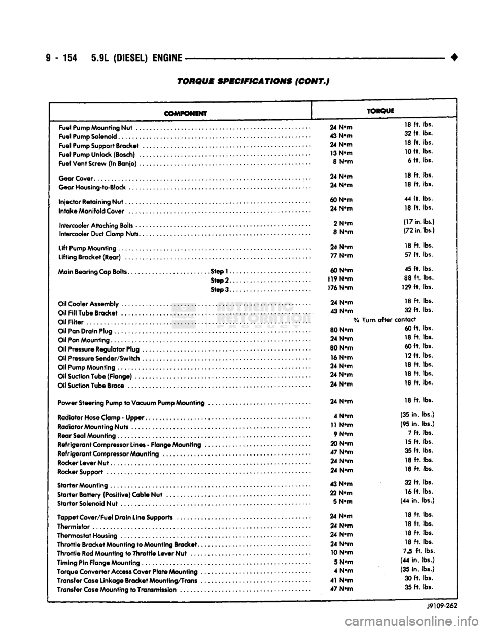
TORQUE
SPECIFICATIONS
(CONT.J
COMPONENT
TORQUE
Fuel
Pump
Mounting
Nut
..
Fuel
Pump
Solenoid
Fuel
Pump
Support
Bracket
Fuel
Pump
Unlock
(Bosch)
.
Fuel
Vent
Screw
(In Banjo)
.
Gear
Cover
Gear
Housing-to-Block
Injector
Retaining Nut.
Intake
Manifold
Cover
Intercooler
Attaching
Bolts
•
•
Intercooler
Duct
Clamp
Nuts.
Lift
Pump
Mounting
Lifting Bracket (Rear)
..
Main
Bearing
Cap
Bolts.
Step!.
Step
2.
Steo3.
Oil
Cooler
Assembly
Oil
Fill
Tube Bracket
Oil
Filter
Oil
Pan
Drain
Plug
Oil
Pan
Mounting.........
Oil
Pressure
Regulator
Plug
Oil
Pressure
Sender/Switch
Oil
Pump
Mounting
Oil
Suction
Tube (Flange)
..
Oil
Suction
Tube
Brace
Power Steering
Pump
to
Vacuum
Pump
Mounting
Radiator Hose Clamp
-
Upper
Radiator Mounting Nuts Rear Seal Mounting
Refrigerant
Compressor
Lines
-
Flange Mounting
Refrigerant
Compressor
Mounting
Rocker Lever Nut
Rocker Support
Starter
Mounting
Starter
Battery
(Positive) Cable Nut
Starter
Solenoid Nut
Tappet
Cover/Fuel Drain Line Supports
Thermistor
,
Thermostat Housing
Throttle
Bracket Mounting to Mounting Bracket.
Throttle
Rod
Mounting to
Throttle
Lever Nut
...
Timing Pin Flange Mounting
Torque Converter
Access
Cover
Plate
Mounting
Transfer
Case
Linkage Bracket Mounting/Trans Transfer
Case
Mounting to
Transmission
..
24
N-m
18
ft.
lbs.
43
N-m
32 ft. lbs.
24
N-m
18
ft.
lbs.
13
N-m
10
ft. lbs.
8
N-m
6 ft. lbs.
24
N-m
18
ft.
lbs.
24
N-m
18
ft.
lbs.
60
N-m
44
ft.
lbs.
24
N-m
18
ft.
lbs.
2
N-m
(17
in.
lbs.)
8
N-m
(72
in.
lbs.)
24
N-m
18
ft.
lbs.
77
N-m
57
ft.
lbs.
60 N-m 45 ft. lbs.
119
N-m
88
ft.
lbs.
176 N-m 129
ft.
lbs.
24
N-m
18
ft.
lbs.
43
N-m
32
ft.
lbs.
Turn
after
contact
80 N-m 60 ft. lbs.
24
N-m
18
ft.
lbs.
80 N-m 60 ft. lbs.
16
N-m
12 ft. lbs.
24
N-m
18
ft.
lbs.
24
N-m
18
ft.
lbs.
24
N-m
18
ft.
lbs.
24
N-m
18
ft.
lbs.
4
N-m
(35 in. lbs.)
11
N-m
(95 in. lbs.)
9 N-m 7
ft.
lbs.
20
N-m
15
ft.
lbs.
47
N-m
35 ft. lbs.
24
N-m
18
ft.
lbs.
24
N-m
18
ft.
lbs.
43
N-m
32
ft.
lbs.
22
N-m
16
ft. lbs.
5
N-m
(44 in. lbs.)
24
N-m
18
ft.
lbs.
24
N-m
18
ft.
lbs.
24
N-m
18
ft.
lbs.
24
N-m
18
ft.
lbs.
10 N-m
73
ft.
lbs.
5
N-m
(44 in. lbs.)
4
N-m
(35
in. lbs.)
41
N-m
30 ft. lbs.
47
N-m
35 ft. lbs.
J9109-262