1993 DODGE TRUCK height
[x] Cancel search: heightPage 691 of 1502
9
• 86 5.9L
ENGINE
•
INTAKE
VALVE
\
MARGIN
/ >
\ACE^
*
STEM
*
VALVE
SPRING
RETAINER
LOCK
GROOVE EXHAUST
VALVE
J9209-127
Fig.
14
intake
and
Exhaust
Waives
REFACING STONE MUST
NOT CUT
VALVE SHROUD Fig.
15 Refacing
Waive
Seats
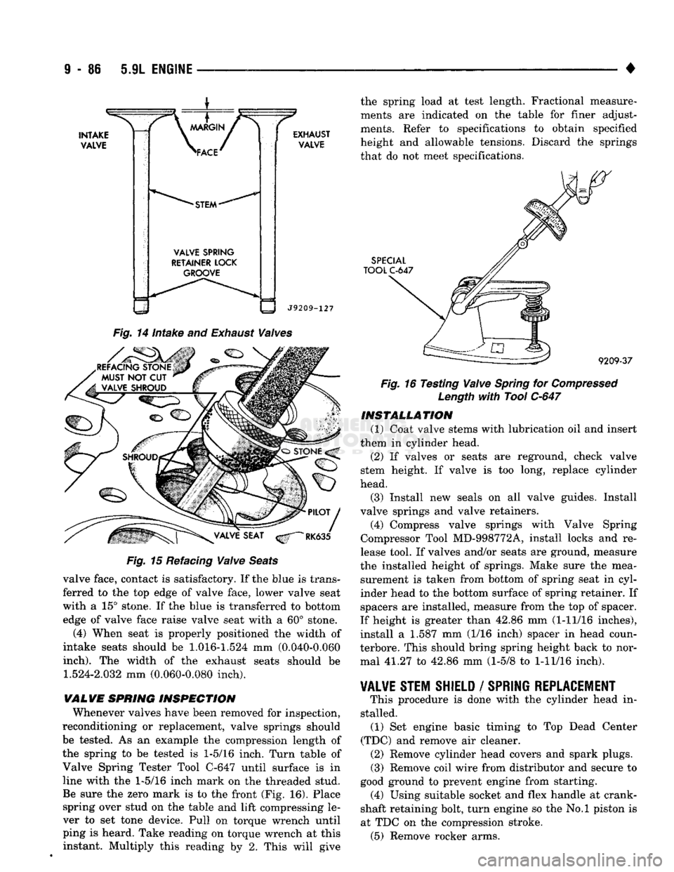
valve face, contact is satisfactory. If the blue is trans ferred to the top edge of valve face, lower valve seat
with a 15° stone. If the blue is transferred to bottom edge of valve face raise valve seat with a 60° stone.
(4) When seat is properly positioned the width of
intake seats should be
1.016-1.524
mm (0.040-0.060
inch).
The width of the exhaust seats should be
1.524-2.032
mm (0.060-0.080 inch).
VALVE
SPRING
INSPECTION
Whenever valves have been removed for inspection,
reconditioning or replacement, valve springs should be tested. As an example the compression length of
the spring to be tested is
1-5/16
inch. Turn table of
Valve Spring Tester Tool C-647 until surface is in
line with the
1-5/16
inch mark on the threaded stud. Be sure the zero mark is to the front (Fig. 16). Place spring over stud on the table and lift compressing le
ver to set tone device. Pull on torque wrench until
ping is heard. Take reading on torque wrench at this instant. Multiply this reading by 2. This will give the spring load at test length. Fractional measure
ments are indicated on the table for finer adjust
ments. Refer to specifications to obtain specified
height and allowable tensions. Discard the springs that do not meet specifications.
SPECIAL
TOOL
C-647
9209-37
Fig.
16 Testing
Waive
Spring
for
Compressed
Length
with
Tool
C-647
INSTALLATION
(1) Coat valve stems with lubrication oil and insert
them in cylinder head.
(2) If valves or seats are reground, check valve
stem height. If valve is too long, replace cylinder
head.
(3) Install new seals on all valve guides. Install
valve springs and valve retainers.
(4) Compress valve springs with Valve Spring
Compressor Tool MD-998772A, install locks and re
lease tool. If valves and/or seats are ground, measure
the installed height of springs. Make sure the mea surement is taken from bottom of spring seat in cyl
inder head to the bottom surface of spring retainer. If
spacers are installed, measure from the top of spacer.
If height is greater than 42.86 mm (1-11/16 inches),
install a 1.587 mm (1/16 inch) spacer in head coun-
terbore. This should bring spring height back to nor mal 41.27 to 42.86 mm (1-5/8 to
1-11/16
inch).
¥AL¥E
STEM SHIELD
/
SPRING REPLACEMENT
This procedure is done with the cylinder head in
stalled. (1) Set engine basic timing to Top Dead Center
(TDC) and remove air cleaner. (2) Remove cylinder head covers and spark plugs. (3) Remove coil wire from distributor and secure to
good ground to prevent engine from starting. (4) Using suitable socket and flex handle at crank
shaft retaining bolt, turn engine so the No.l piston is
at TDC on the compression stroke. (5) Remove rocker arms.
Page 710 of 1502
5.9L
ENGINE
9 - 105
ENGINE SPECIFICATIONS
(CONT.J
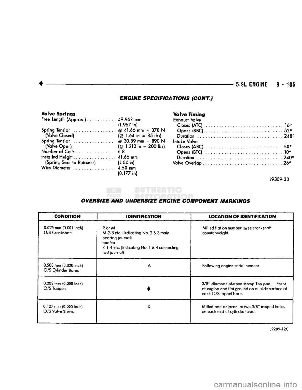
Valve
Springs
Free Length
(Approx.)...........
49.962
mm f1.967 in)
Spring
Tension ................ @ 41.66 mm = 378 N
(Valve Closed) (@ 1.64 in « 85 lbs)
Spring
Tension @ 30.89 mm = 890 N (Valve Open) (@ 1.212 in = 200 lbs)
Number of Coils ............... 6.8
Installed Height 41.66 mm (Spring Seat to Retainer) (1.64 in)
Wire Diameter ................ 4.50 mm
(0.177
in) Valve
Timing
Exhaust
Valve
Closes
(ATC) ............. 16°
Opens
(BBC) .................. ....... 52° Duration 248°
Intake Valve
Closes
(ABC) 50°
Opens
(BTC) 10° Duration ................. 240°
Valve Overlap.............................. 26°
J9309-33
OVERSIZE
AND
UNDERSIZE
ENGINE COMPONENT MARKINGS
CONDITION
IDENTIFICATION
LOCATION
OF
IDENTIFICATION
0.025
mm
(0.001
inch)
U/S
Crankshaft
RorM
M-2-3 etc. (Indicating No. 2 & 3 main bearing journal)
and/or
R-l-4 etc. (Indicating No. 1 & 4 connecting
rod journal) Milled
flat
on number
three
crankshaft
counterweight
0.508
mm
(0.020
inch)
O/S
Cylinder Bores
A
Following engine serial number.
0.203
mm
(0.008
inch)
O/S
Tappets • 3/8" diamond-shaped stamp Top pad — Front
of engine and
flat
ground on outside surface of
each O/S tappet bore.
0.127 mm
(0.005
inch)
O/S
Valve Stems
X
Milled pad adjacent to two 3/8" tapped holes
on
each end of cylinder head.
J9209-120
Page 720 of 1502
* ^ ^ ^ — 5.IL
(DIESEL) ENGINE
9 - 115
MIN. 102.0 mm (4.0157 inch) MAX. 102.1 16 mm (4.0203 inch)
Out-of-Round 0.038 mm (0.0015 inch)
Taper 0.76 mm (0.003 inch) Oversize pistons and rings are
available for bored cylinder blocks.
J9109-75
Fig.
8 Cylinder
Bore
Diameter
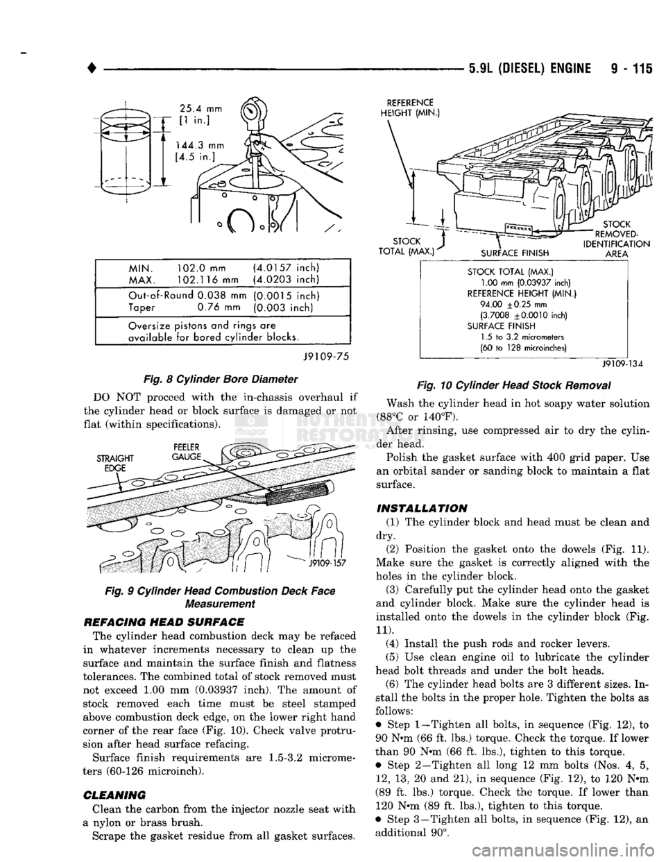
DO NOT proceed with the in-chassis overhaul if
the cylinder head or block surface is damaged or not
flat (within specifications).
Fig.
9 Cylinder Head
Combustion
Deck
Face
Measurement
REFACING
HEAD
SURFACE
The cylinder head combustion deck may be refaced
in whatever increments necessary to clean up the
surface and maintain the surface finish and flatness
tolerances. The combined total of stock removed must
not exceed 1.00 mm (0.03937 inch). The amount of stock removed each time must be steel stamped above combustion deck edge, on the lower right hand
corner of the rear face (Fig. 10). Check valve protru sion after head surface refacing.
Surface finish requirements are
1.5-3.2
microme
ters (60-126 microinch).
CLEANING
Clean the carbon from the injector nozzle seat with
a nylon or brass brush. Scrape the gasket residue from all gasket surfaces.
REFERENCE
STOCK
TOTAL
(MAX.)
1.00 mm
(0.03937
inch)
REFERENCE
HEIGHT
(MIN.)
94.00
±0.25
mm
(3.7008
±0.0010
inch)
SURFACE
FINISH
1.5 to 3.2 micrometers
(60 to 128 microinches)
J9109-134
Fig.
10 Cylinder Head
Stock
Removal
Wash the cylinder head in hot soapy water solution
(88°C or 140°F). After rinsing, use compressed air to dry the cylin
der head.
Polish the gasket surface with 400 grid paper. Use
an orbital sander or sanding block to maintain a flat
surface.
INSTALLATION
(1) The cylinder block and head must be clean and
dry. (2) Position the gasket onto the dowels (Fig. 11).
Make sure the gasket is correctly aligned with the
holes in the cylinder block.
(3)
Carefully put the cylinder head onto the gasket
and cylinder block. Make sure the cylinder head is
installed onto the dowels in the cylinder block (Fig.
11).
(4) Install the push rods and rocker levers.
(5) Use clean engine oil to lubricate the cylinder
head bolt threads and under the bolt heads. (6) The cylinder head bolts are 3 different sizes. In
stall the bolts in the proper hole. Tighten the bolts as
follows: • Step
1—Tighten
all bolts, in sequence (Fig. 12), to
90 N#m (66 ft. lbs.) torque. Check the torque. If lower
than 90 N*m (66 ft. lbs.), tighten to this torque. • Step 2—Tighten all long 12 mm bolts (Nos. 4, 5,
12,
13, 20 and 21), in sequence (Fig. 12), to 120 N*m
(89 ft. lbs.) torque. Check the torque. If lower than 120 N«m (89 ft. lbs.), tighten to this torque.
• Step 3 —Tighten all bolts, in sequence (Fig. 12), an additional 90°.
Page 723 of 1502
i - 118 5.9L
(DIESEL) ENGINE
VALVE GUIDE
BORES
EXHAUST CYLINDER
HEAD
INTAKE
CYLINDER HEAD VALVE GUIDE
BORES
CYLINDER HEAD VALVE GUIDE
BORES
11.125
±0.013 mm (0.438 ± 0.0005 in)
VALVE GUIDE
BORES
8.029
±0.010
mm
(0.3161 ±0.0004 in)
J9109-136
Fig.
6
Service
Valve
Guides—Thin
Wall
VALVE GUIDE
BORES
CYLINDER HEAD
EXHAUST INTAKE
CYLINDER HEAD VALVE GUIDE
BORES
CYLINDER HEAD VALVE GUIDE
BORES
14.000 ±0.013
mm
(0.5512 ± 0.0005 in)
VALVE GUIDE
BORES
8.029
±0.010
mm
(0.3161 ±0.0004 in)
J9109-137
Fig.
7
Service
Valve
Guides—Thick
Wall
VALVE
SPRINGS
Measure
the
valve spring length.
The
approximate
free length
is
55.63
mm
(2.190 inch) with
the
maxi mum inclination
of 1.0 mm
(0.039 inch).
Measure
the
valve spring force. 289.32
N (65 lbs.)
is
the
minimum acceptable load required
to
compress
the spring
to a
height
of
49.25
mm (1.94
inch). If
the
valve spring does
not
meet
the
limits above,
replace
the
spring.
VALVE
SEATS
INSPECTION
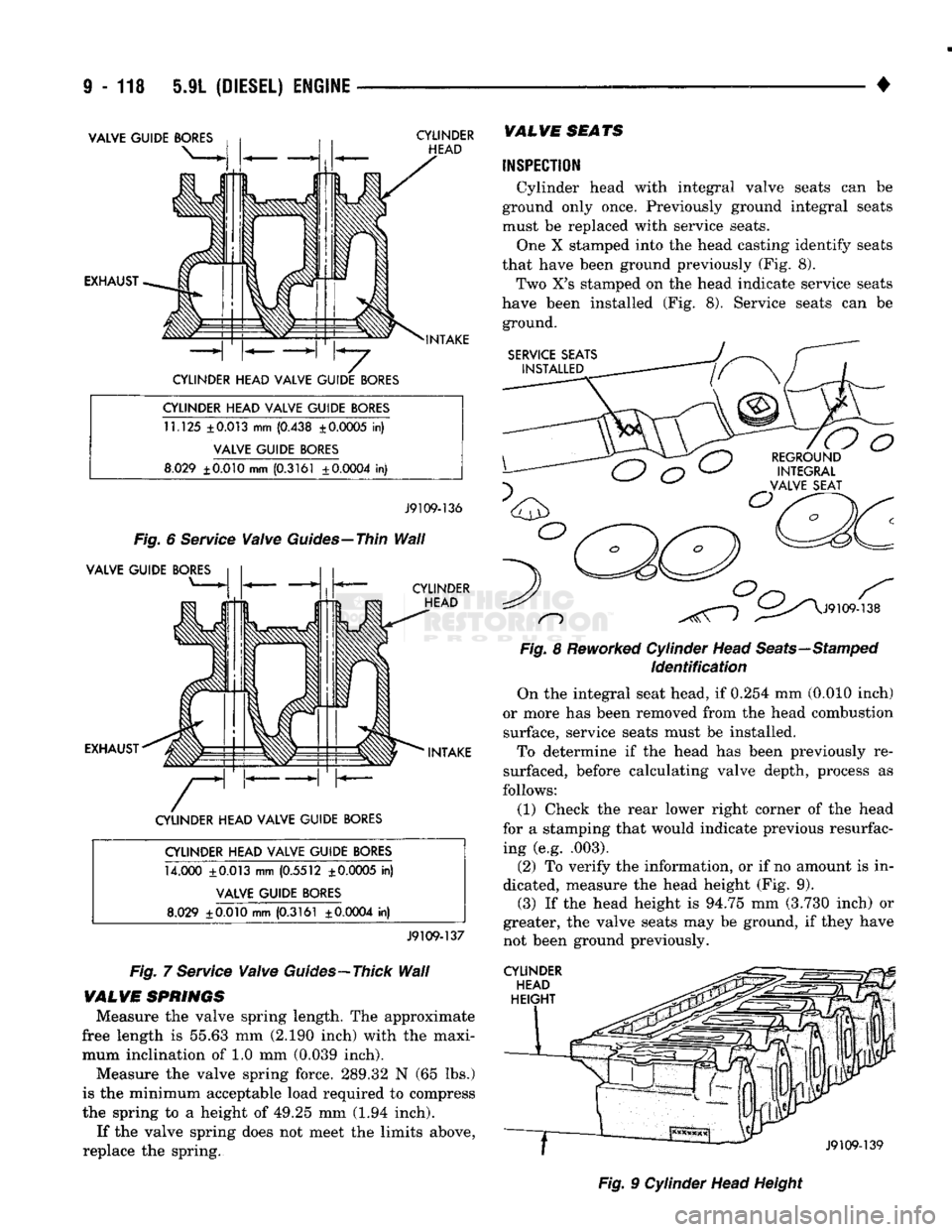
Cylinder head with integral valve seats
can be
ground only once. Previously ground integral seats
must
be
replaced with service seats. One
X
stamped into
the
head casting identify seats
that have been ground previously
(Fig. 8).
Two
X's
stamped
on the
head indicate service seats
have been installed
(Fig. 8).
Service seats
can be
ground.
SERVICE SEATS
INSTALLED
n
o
REGROUND INTEGRAL
VALVE SEAT
J9109-138
Fig.
8
Reworked
Cylinder Head
Seats—Stamped
Identification
On
the
integral seat head,
if
0.254
mm
(0.010 inch)
or more
has
been removed from
the
head combustion surface, service seats must
be
installed. To determine
if the
head
has
been previously
re
surfaced, before calculating valve depth, process
as
follows:
(1) Check
the
rear lower right corner
of the
head
for
a
stamping that would indicate previous resurfac ing
(e.g.
.003).
(2)
To
verify
the
information,
or if no
amount
is in
dicated, measure
the
head height
(Fig. 9).
(3)
If the
head height
is
94.75
mm
(3.730 inch)
or
greater,
the
valve seats
may be
ground,
if
they have
not been ground previously.
CYLINDER
HEAD
HEIGHT
J9109-139
Fig.
9
Cylinder Head Height
Page 733 of 1502
9
- 128 5.9L
(DIESEL)
ENGINE
•
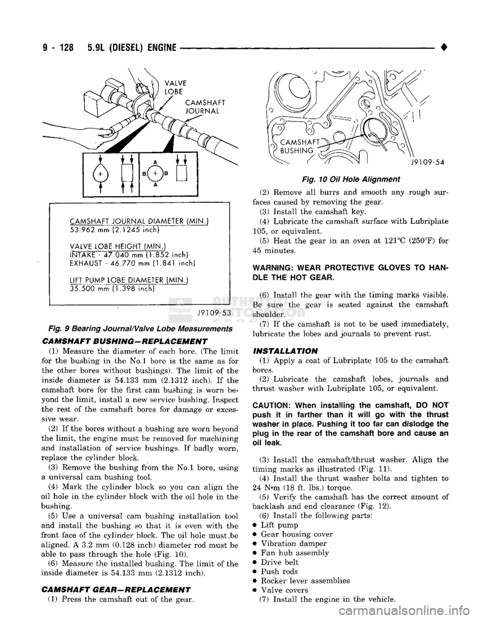
CAMSHAFT
JOURNAL
CAMSHAFT
JOURNAL
DIAMETER
(MIN.
53.962 mm (2.1245
inch)
VALVE
LOBE
HEIGHT
(MIN..)
INTAKE
- 47.040 mm (1.852
inch)
EXHAUST
- 46.770 mm (1.841
inch)
LIFT
PUMP
LOBE
DIAMETER
(MIN.)
35.500 mm (1.398
inch)
J9109-53
Fig.
9 Bearing Journal/Valve
Lobe
Measurements
CAMSHAFT
BUSHING-REPLACEMENT
(1) Measure the diameter of each bore. (The limit
for the bushing in the No.l bore is the same as for
the other bores without bushings). The limit of the inside diameter is 54.133 mm (2.1312 inch). If the
camshaft bore for the first cam bushing is worn be
yond the limit, install a new service bushing. Inspect the rest of the camshaft bores for damage or exces sive wear.
(2) If the bores without a bushing are worn beyond
the limit, the engine must be removed for machining and installation of service bushings. If badly worn,
replace the cylinder block.
(3) Remove the bushing from the No.l bore, using
a universal cam bushing tool.
(4) Mark the cylinder block so you can align the
oil hole in the cylinder block with the oil hole in the
bushing.
(5) Use a universal cam bushing installation tool
and install the bushing so that it is even with the
front face of the cylinder block. The oil hole must .be aligned. A 3.2 mm (0.128 inch) diameter rod must be able to pass through the hole (Fig. 10). (6) Measure the installed bushing. The limit of the
inside diameter is 54.133 mm (2.1312 inch).
CAMSHAFT
GEAR-REPLACEMENT
(1) Press the camshaft out of the gear. J9109-54
Fig.
10 Oil Hole
Alignment
(2) Remove all burrs and smooth any rough sur
faces caused by removing the gear. (3) Install the camshaft key.
(4) Lubricate the camshaft surface with Lubriplate
105,
or equivalent.
(5) Heat the gear in an oven at 121°C (250°F) for
45 minutes.
WARNING:
WEAR
PROTECTIVE
GLOVES
TO
HAN
DLE
THE HOT
GEAR.
(6) Install the gear with the timing marks visible.
Be sure the gear is seated against the camshaft shoulder.
(7) If the camshaft is not to be used immediately,
lubricate the lobes and journals to prevent rust.
INSTALLATION
(1) Apply a coat of Lubriplate 105 to the camshaft
bores.
(2) Lubricate the camshaft lobes, journals and
thrust washer with Lubriplate 105, or equivalent.
CAUTION:
When
installing
the
camshaft,
DO NOT
push
it in
farther
than
it
will
go
with
the
thrust
washer
in
place.
Pushing
it too far
can
dislodge
the
plug
in the
rear
of the
camshaft
bore
and
cause
an
oil
leak.
(3) Install the camshaft/thrust washer. Align the
timing marks as illustrated (Fig. 11). (4) Install the thrust washer bolts and tighten to
24 N-m (18 ft. lbs.) torque.
(5) Verify the camshaft has the correct amount of
backlash and end clearance (Fig. 12).
(6) Install the following parts:
• Lift pump • Gear housing cover
• Vibration damper
• Fan hub assembly
• Drive belt
• Push rods
• Rocker lever assemblies
• Valve covers (7) Install the engine in the vehicle.
Page 752 of 1502
5.9L
(DIESEL) ENGINE
9 - 149
FILTER
BYPASS-
VALVE
OIL COOLER COVER
Fig. 9
Removing
Filter
Bypass
Valve
n
J9109-16
FILTER
BYPASS
VALVE OIL COOLER
COVER
J9109-15
Fig. 10 Installing New
Filter
Bypass
Valve
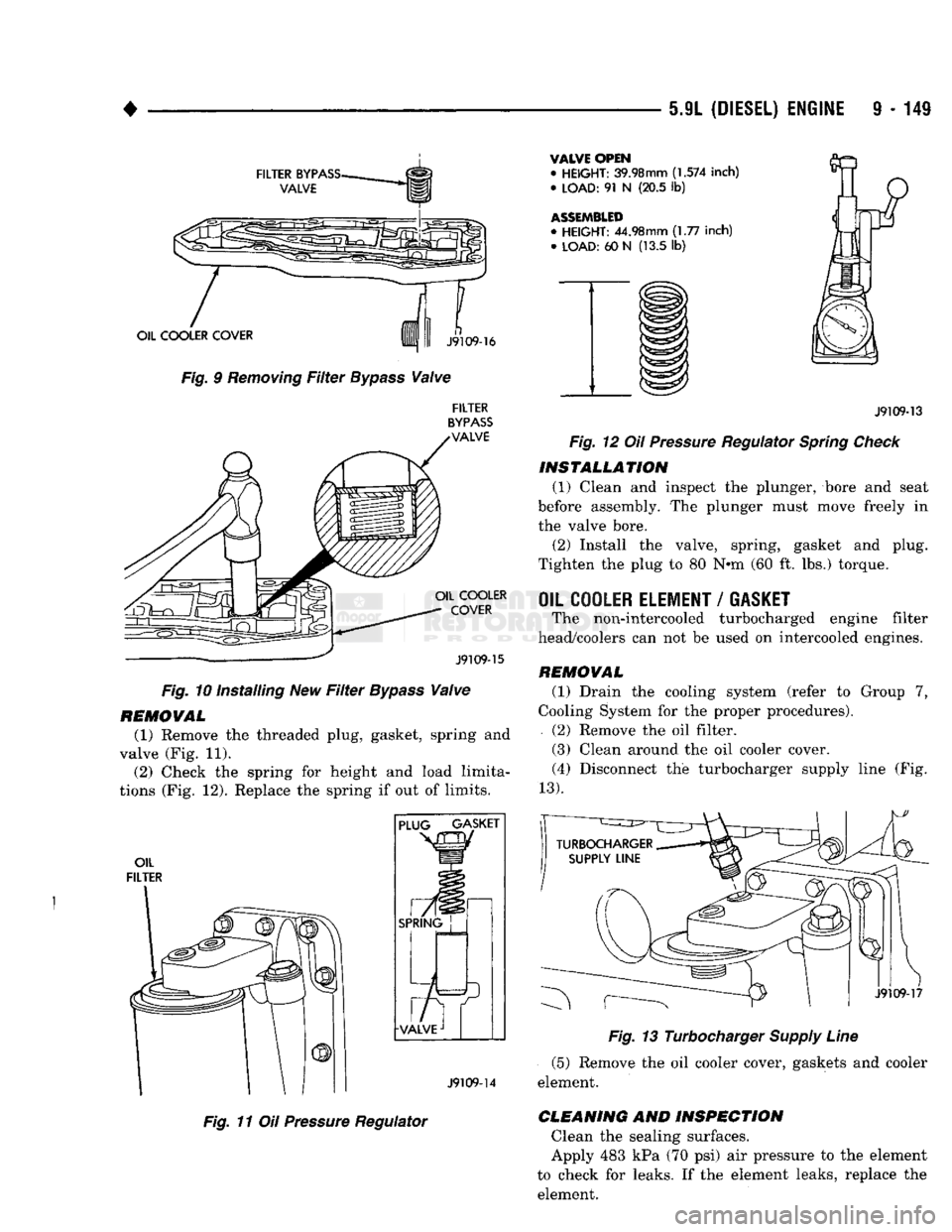
REMOVAL
(1) Remove the threaded plug, gasket, spring and
valve (Fig. 11). (2) Check the spring for height and load limita
tions (Fig. 12). Replace the spring if out of limits.
OIL
FILTER PLUG GASKET
SPRING
J9109-14
Fig. 11 Oil
Pressure
Regulator
VALVE OPEN
•
HEIGHT:
39.98mm
(1.574
inch)
•
LOAD:
91 N (20.5 lb)
ASSEMBLED
•
HEIGHT:
44.98mm (1.77 inch) •
LOAD:
60 N (13.5 lb)
J9109-13
Fig. 12 Oil
Pressure
Regulator
Spring
Check
INSTALLATION
(1) Clean and inspect the plunger, bore and seat
before assembly. The plunger must move freely in
the valve bore.
(2) Install the valve, spring, gasket and plug.
Tighten the plug to 80 N*m (60 ft. lbs.) torque.
OIL COOLER ELEMENT
/
GASKET
The non-intercooled turbocharged engine filter
head/coolers can not be used on intercooled engines.
REMOVAL
(1) Drain the cooling system (refer to Group 7,
Cooling System for the proper procedures).
(2) Remove the oil filter.
(3) Clean around the oil cooler cover. (4) Disconnect the turbocharger supply line (Fig.
13).
J9109-17
Fig. 13 Turbocharger
Supply
Line
(5) Remove the oil cooler cover, gaskets and cooler
element.
CLEANING
AND
INSPECTION
Clean the sealing surfaces.
Apply 483 kPa (70 psi) air pressure to the element
to check for leaks. If the element leaks, replace the element.
Page 790 of 1502
•
FRAME
AND
BUMPERS
13 - 3
SNOW
PLOW
NDEX
page
Power
Angling Cylinder Service
16
Power
Unit
. . 13
Service
Information
3
Snow
Plow Control Module
17
Snow
Plow Frame
16
SERVICE
INFORMATION
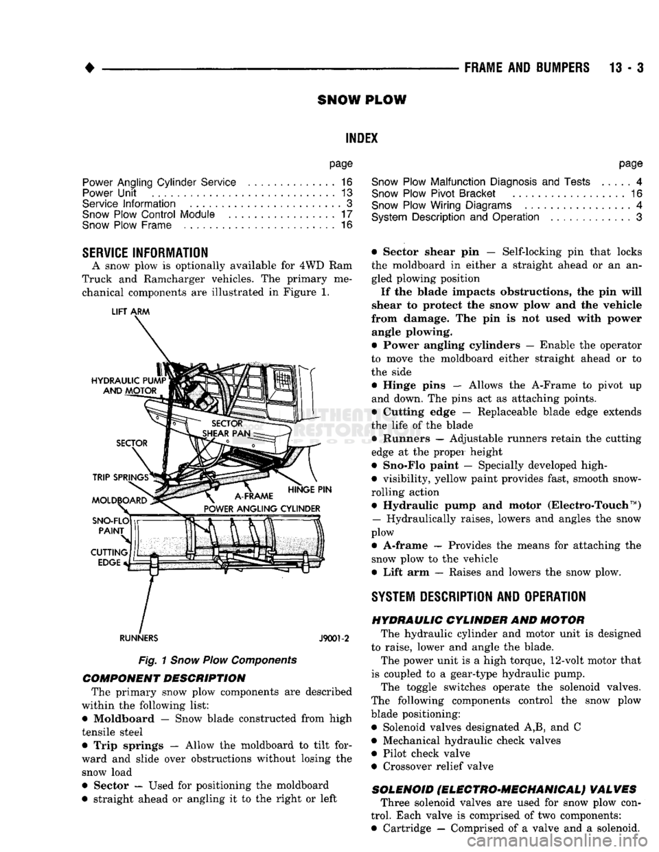
A snow plow is optionally available for 4WD Ram
Truck and Ramcharger vehicles. The primary me chanical components are illustrated in Figure 1.
LIFT
ARM
RUNNERS
J9001-2
Fig.
1
Snow
Plow
Components
COMPONENT DESCRIPTION
The primary snow plow components are described
within the following list:
• Moldboard — Snow blade constructed from high
tensile steel
• Trip springs — Allow the moldboard to tilt for
ward and slide over obstructions without losing the snow load
• Sector — Used for positioning the moldboard
• straight ahead or angling it to the right or left
page
Snow
Plow Malfunction
Diagnosis
and
Tests
4
Snow
Plow Pivot Bracket
16
Snow
Plow Wiring Diagrams
4
System
Description
and
Operation
3
• Sector shear pin — Self-locking pin that locks the moldboard in either a straight ahead or an an
gled plowing position
If the blade impacts obstructions, the pin will
shear to protect the snow plow and the vehicle
from damage. The pin is not used with power angle plowing.
• Power angling cylinders — Enable the operator
to move the moldboard either straight ahead or to
the side
• Hinge pins — Allows the A-Frame to pivot up
and down. The pins act as attaching points.
• Cutting edge — Replaceable blade edge extends
the life of the blade • Runners — Adjustable runners retain the cutting
edge at the proper height
• Sno-Flo paint — Specially developed high-
• visibility, yellow paint provides fast, smooth snow-
rolling action • Hydraulic pump and motor (Electro-Touch ™)
— Hydraulically raises, lowers and angles the snow
plow
• A-frame — Provides the means for attaching the snow plow to the vehicle
• Lift arm — Raises and lowers the snow plow.
SYSTEM
DESCRIPTION
AND OPERATION HYDRAULIC CYLINDER
AND
MOTOR
The hydraulic cylinder and motor unit is designed
to raise, lower and angle the blade. The power unit is a high torque, 12-volt motor that
is coupled to a gear-type hydraulic pump. The toggle switches operate the solenoid valves.
The following components control the snow plow blade positioning: • Solenoid valves designated A,B, and C
• Mechanical hydraulic check valves
• Pilot check valve
• Crossover relief valve
SOLENOID
fELEGTRO'MEGHANIGALj VALVES
Three solenoid valves are used for snow plow con
trol. Each valve is comprised of two components:
• Cartridge — Comprised of a valve and a solenoid.
Page 796 of 1502
•
FRAME
AND
1UMPERS
-13 - S
SNOW
PLOW
DIAGNOSIS
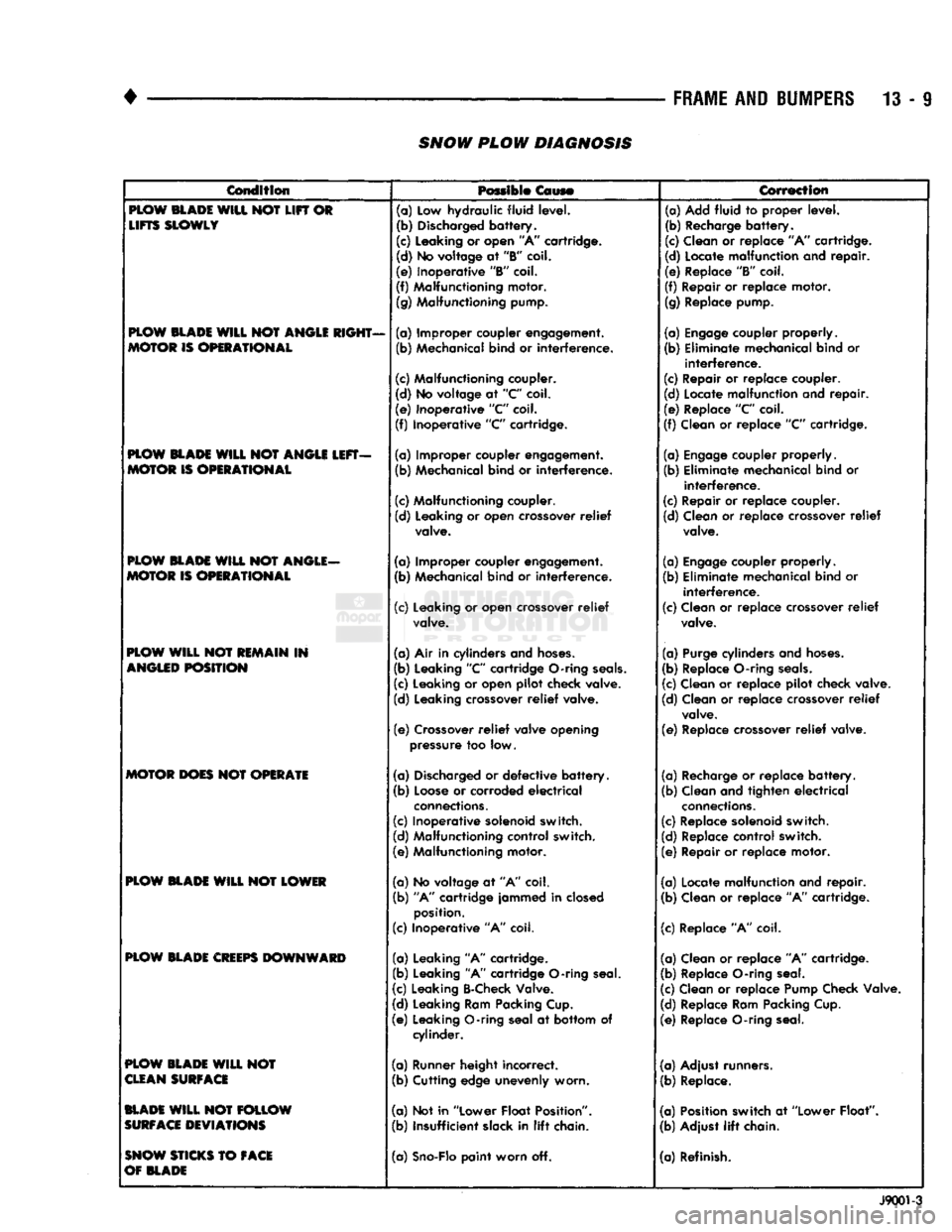
Condition
Possible
Coys®
Correction
PLOW
BLADE
WILL NOT LIFT OR
LIFTS
SLOWLY
PLOW
BLADE
WILL
NOT
ANGLE
RIGHT-
MOTOR
IS
OPERATIONAL
PLOW
BLADE
WILL NOT
ANGLE
LEFT-
MOTOR
IS
OPERATIONAL
PLOW
BLADE
WILL NOT
ANGLE-
MOTOR
IS
OPERATIONAL
PLOW
WILL NOT
REMAIN
IN
ANGLED
POSITION
MOTOR
DOES
NOT
OPERATE
PLOW
BLADE
WILL NOT
LOWER
PLOW
BLADE
CREEPS
DOWNWARD
PLOW
BLADE
WILL NOT
CLEAN
SURFACE
BLADE
WILL NOT
FOLLOW
SURFACE
DEVIATIONS
SNOW
STICKS
TO
FACE
OF
BLADE
(n)
Low hydraulic fluid level.
(b) Discharged
battery.
(c) Leaking or open "A" cartridge.
(d) No voltage at
"B"
coil.
(e) Inoperative
"B"
coil.
(f) Malfunctioning motor.
(g) Malfunctioning pump.
(a) Improper coupler engagement.
(b) Mechanical bind or
interference.
(c) Malfunctioning coupler.
(d) No voltage at
"C"
coil.
(e) Inoperative "C" coil.
(f) Inoperative
"C"
cartridge.
(a) Improper coupler engagement.
(b) Mechanical bind or
interference.
(c) Malfunctioning coupler.
(d) Leaking or open crossover
relief
valve.
(a) Improper coupler engagement. (b) Mechanical bind or
interference.
(c) Leaking or open crossover
relief
valve.
(a) Air in cylinders and
hoses.
(b) Leaking
"C"
cartridge O-ring
seals.
(c) Leaking or open pilot check valve.
(d) Leaking crossover
relief
valve.
(e)
Crossover
relief
valve opening
pressure too low.
(a) Discharged or
defective
battery.
(b)
Loose
or corroded
electrical
connections.
(c) Inoperative solenoid switch.
(d) Malfunctioning control switch.
(e) Malfunctioning motor.
(a) No voltage at "A" coil.
(b)
"A" cartridge jammed in closed
position.
(c) Inoperative "A" coil.
(a) Leaking "A" cartridge.
(b) Leaking "A" cartridge O-ring seal.
(c) Leaking B-Check Valve.
(d) Leaking Ram Packing Cup.
(e) Leaking O-ring seal at bottom of cylinder.
(a) Runner height incorrect. (b) Cutting edge unevenly worn.
(a) Not in "Lower Float Position".
(b) Insufficient slack in
lift
chain.
(a)
Sno-Flo
paint worn off. (a) Add fluid to proper level.
(b) Recharge
battery.
(c) Clean or replace "A" cartridge.
(d) Locate malfunction and
repair.
(e) Replace
"B"
coil.
(f) Repair or replace motor. (g) Replace pump.
(a)
Engage
coupler properly.
(b) Eliminate mechanical bind or
interference.
(c) Repair or replace coupler.
(d) Locate malfunction and
repair.
(e) Replace
"C"
coil.
(f) Clean or replace
"C"
cartridge.
(a)
Engage
coupler properly.
(b) Eliminate mechanical bind or
interference.
(c) Repair or replace coupler.
(d) Clean or replace crossover
relief
valve.
(a)
Engage
coupler properly.
(b) Eliminate mechanical bind or
interference.
(c) Clean or replace crossover
relief
valve.
(a) Purge cylinders and
hoses.
(b) Replace O-ring
seals.
(c) Clean or replace pilot check valve.
(d) Clean or replace crossover
relief
valve.
(e) Replace crossover
relief
valve.
(a) Recharge or replace
battery.
(b) Clean and tighten
electrical
connections.
(c) Replace solenoid switch.
(d) Replace control switch.
(e) Repair or replace motor.
(a) Locate malfunction and
repair.
(b) Clean or replace "A" cartridge.
(c) Replace "A" coil.
(a) Clean or replace "A" cartridge.
(b) Replace O-ring seal.
(c) Clean or replace Pump Check Valve.
(d) Replace Ram Packing Cup.
(e) Replace O-ring seal.
(a) Adjust runners.
(b) Replace.
(a) Position switch at "Lower Float"
(b) Adjust
lift
chain.
(a) Refinish.
J9001-3