1993 DODGE TRUCK height
[x] Cancel search: heightPage 134 of 1502
•
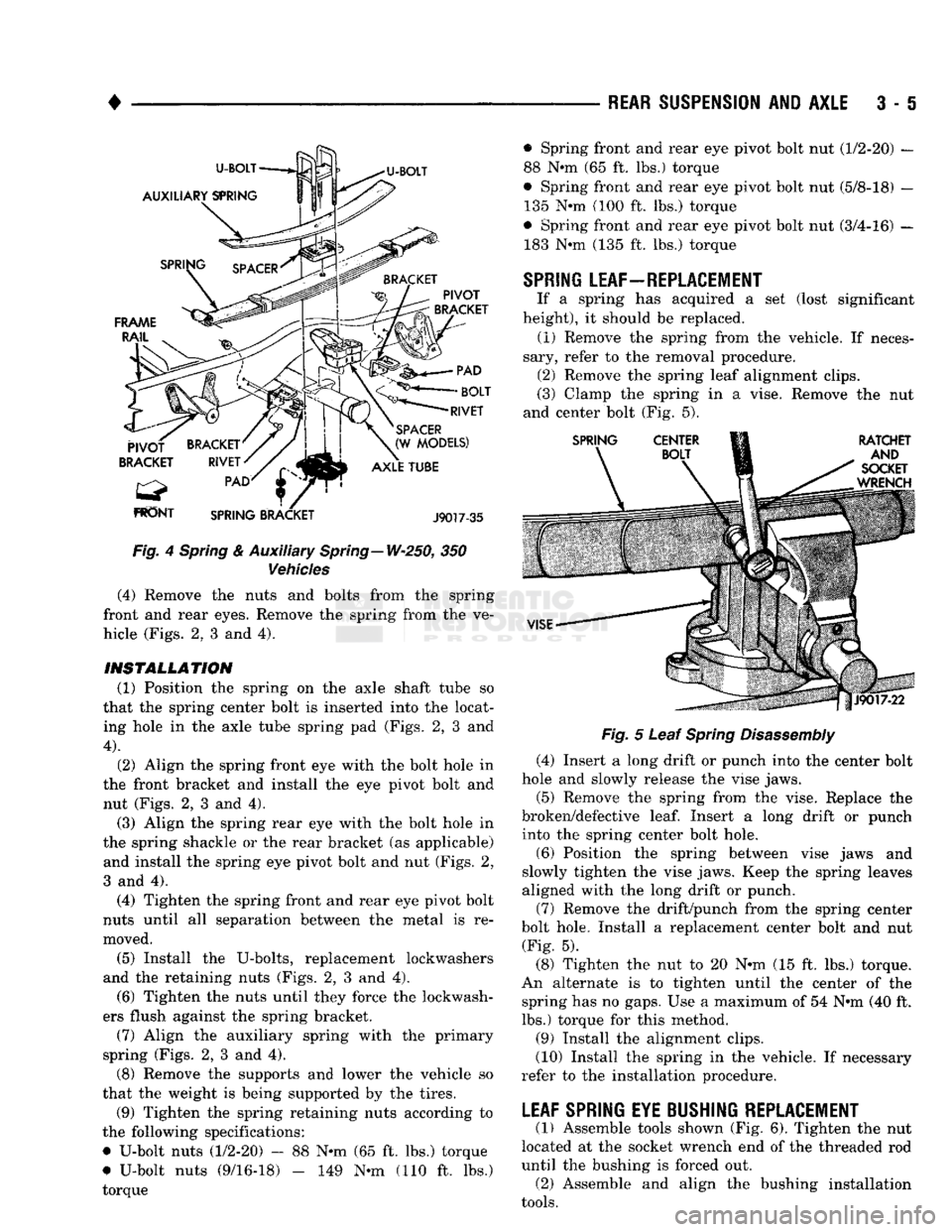
Fig.
4
Spring
& Auxiliary Spring—W-250, 350
Vehicles
(4) Remove the nuts and bolts from the spring
front and rear eyes. Remove the spring from the ve
hicle (Figs. 2, 3 and 4).
INSTALLATION (1) Position the spring on the axle shaft tube so
that the spring center bolt is inserted into the locat ing hole in the axle tube spring pad (Figs. 2, 3 and
4).
(2) Align the spring front eye with the bolt hole in
the front bracket and install the eye pivot bolt and nut (Figs. 2, 3 and 4). (3) Align the spring rear eye with the bolt hole in
the spring shackle or the rear bracket (as applicable) and install the spring eye pivot bolt and nut (Figs. 2,
3 and 4).
(4) Tighten the spring front and rear eye pivot bolt
nuts until all separation between the metal is re
moved.
(5) Install the U-bolts, replacement lockwashers
and the retaining nuts (Figs. 2, 3 and 4). (6) Tighten the nuts until they force the lockwash
ers flush against the spring bracket. (7) Align the auxiliary spring with the primary
spring (Figs. 2, 3 and 4).
(8) Remove the supports and lower the vehicle so
that the weight is being supported by the tires.
(9) Tighten the spring retaining nuts according to
the following specifications:
• U-bolt nuts (1/2-20) - 88 N*m (65 ft. lbs.) torque
# U-bolt nuts (9/16-18) - 149 N-m (110 ft. lbs.)
torque —
REAR SUSPENSION
AND
AXLE
3 • 5
Fig.
5 Leaf
Spring
Disassembly
(4) Insert a long drift or punch into the center bolt
hole and slowly release the vise jaws.
(5) Remove the spring from the vise. Replace the
broken/defective
leaf.
Insert a long drift or punch into the spring center bolt hole.
(6) Position the spring between vise jaws and
slowly tighten the vise jaws. Keep the spring leaves
aligned with the long drift or punch.
(7) Remove the drift/punch from the spring center
bolt hole. Install a replacement center bolt and nut (Fig. 5).
(8) Tighten the nut to 20 N-m (15 ft. lbs.) torque.
An alternate is to tighten until the center of the spring has no gaps. Use a maximum of 54 N*m (40 ft.
lbs.) torque for this method.
(9) Install the alignment clips.
(10) Install the spring in the vehicle. If necessary
refer to the installation procedure.
LEAF SPRING EYE BUSHING REPLACEMENT
(1) Assemble tools shown (Fig. 6). Tighten the nut
located at the socket wrench end of the threaded rod
until the bushing is forced out. (2) Assemble and align the bushing installation
tools.
• Spring front and rear eye pivot bolt nut (1/2-20) —
88 N«m (65 ft. lbs.) torque
© Spring front and rear eye pivot bolt nut (5/8-18) — 135 N»m (100 ft. lbs.) torque
• Spring front and rear eye pivot bolt nut (3/4-16) — 183 N-m (135 ft. lbs.) torque
SPRING
LEAF—REPLACEMENT
If a spring has acquired a set (lost significant
height), it should be replaced. (1) Remove the spring from the vehicle. If neces
sary, refer to the removal procedure. (2) Remove the spring leaf alignment clips.
(3) Clamp the spring in a vise. Remove the nut
and center bolt (Fig. 5).
Page 143 of 1502
3
- 14
REAR SUSPENSION
AND
AXLE
3
- 18
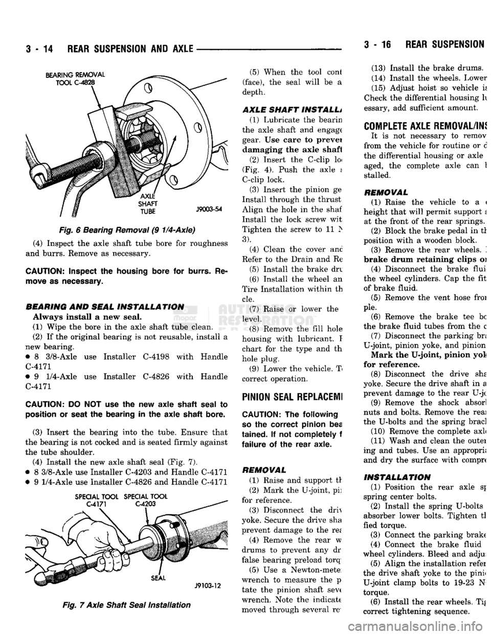
REAR SUSPENSION Fig.
6 Bearing
Removal
(9
1/4-Axle)
(4) Inspect the axle shaft tube bore for roughness
and burrs. Remove as necessary.
CAUTION:
Inspect
the
housing
bore for
burrs.
Re
move
as
necessary.
BEARING
AND
SEAL
INSTALLATION
Always install a new seal. (1) Wipe the bore in the axle shaft tube clean.
(2) If the original bearing is not reusable, install a
new bearing.
• 8 3/8-Axle use Installer C-4198 with Handle
C-4171
• 9
1/4-Axle
use Installer C-4826 with Handle
C-4171
CAUTION:
DO NOT use the new axle
shaft
seal
to
position
or
seat
the bearing in the axle
shaft
bore.
(3) Insert the bearing into the tube. Ensure that
the bearing is not cocked and is seated firmly against
the tube shoulder.
(4) Install the new axle shaft seal (Fig. 7).
• 8 3/8-Axle use Installer C-4203 and Handle C-4171
• 9
1/4-Axle
use Installer C-4826 and Handle C-4171
SPECIAL
TOOL
SPECIAL
TOOL
Fig.
7 Axle Shaft
Seal
Installation
(5) When the tool cont
(face),
the seal will be a
depth.
AXLE SHAFT INSTALL* (1) Lubricate the bearin
the axle shaft and engage gear. Use care to prevei damaging the axle shaft
(2) Insert the C-clip loi
(Fig. 4). Push the axle s
C-clip lock.
(3) Insert the pinion ge
Install through the thrust
Align the hole in the shaf
Install the lock screw wit
Tighten the screw to 11 Is
3).
(4) Clean the cover anc
Refer to the Drain and Re
(5) Install the brake drv
(6) Install the wheel an
Tire Installation within th
cle.
(7) Raise or lower the
level.
(8) Remove the fill hole
housing with lubricant. I chart for the type and th
hole plug.
(9) Lower the vehicle. T
correct operation.
PINION
SEAL REPLACE!!
CAUTION:
The following
so
the correct pinion bea
tained.
If not completely f
failure
of the rear axle.
REMOVAL (1) Raise and support tr
(2) Mark the U-joint, pi]
for reference.
(3) Disconnect the drh
yoke. Secure the drive sha
prevent damage to the re*
(4) Remove the rear w
drums to prevent any dr
false bearing preload torq
(5) Use a Newton-mete
wrench to measure the p
tate the pinion shaft sev( wrench. Note the indicate moved through several re' (13) Install the brake drums.
(14) Install the wheels. Lower
(15) Adjust hoist so vehicle k
Check the differential housing h
essary, add sufficient amount.
COMPLETE AXLE REMOVAL/IN!
It is not necessary to remov
from the vehicle for routine or d
the differential housing or axle aged, the complete axle can 1
stalled.
REMOVAL (1) Raise the vehicle to a <
height that will permit support t at the front of the rear springs. (2) Block the brake pedal in tl
position with a wooden block. (3) Remove the rear wheels. '.
brake drum retaining clips oi
(4) Disconnect the brake flui
the wheel cylinders. Cap the fit of brake fluid.
(5) Remove the vent hose froi
pie.
(6) Remove the brake tee be
the brake fluid tubes from the c (7) Disconnect the parking bn
U-joint, pinion yoke, and pinion
Mark the U-joint, pinion yol
for reference. (8) Disconnect the drive she
yoke. Secure the drive shaft in a prevent damage to the rear U-jc
(9) Remove the shock absorl
nuts and bolts. Remove the reai
the U-bolts and the spring brad
(10) Remove the complete axL
(11) Wash and clean the outei
ing and tubes. Use an appropri; and dry the surface with comprc
INSTALLATION
(1) Position the rear axle sj
spring center bolts.
(2) Install the spring U-bolts
absorber lower bolts. Tighten tl
fled torque.
(3) Connect the parking brake
(4) Connect the brake fluid
wheel cylinders. Bleed and adjui (5) Align the installation refer
the drive shaft yoke to the pinii U-joint clamp bolts to 19-23 N
torque.
(6) Install the rear wheels. Ti|
correct tightening sequence.
Page 168 of 1502
•
REAR SUSPENSION
AND
AXLE
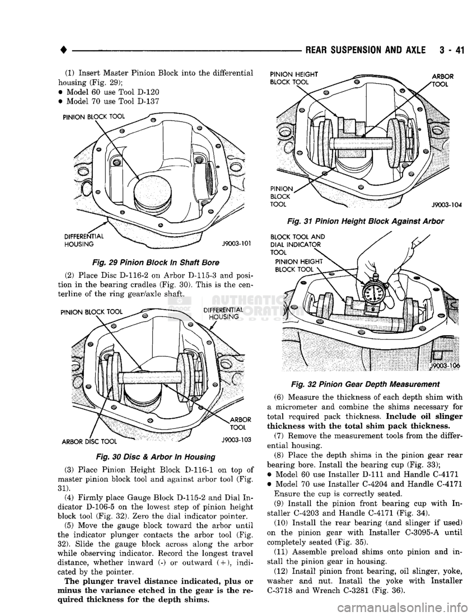
3 - 41 (1) Insert Master Pinion Block into the differential
housing (Fig. 29);
• Model 60 use Tool D-120
• Model 70 use Tool D-137
Fig.
29
Pinion
Block
In Shaft
Bore
(2) Place Disc D-116-2 on Arbor D-115-3 and posi
tion in the bearing cradles (Fig. 30). This is the cen
terline of the ring gear/axle shaft.
Fig.
30
Disc
&
Arbor
In
Housing
(3) Place Pinion Height Block D-116-1 on top of
master pinion block tool and against arbor tool (Fig.
31).
(4) Firmly place Gauge Block D-115-2 and Dial In
dicator D-106-5 on the lowest step of pinion height
block tool (Fig. 32). Zero the dial indicator pointer.
(5) Move the gauge block toward the arbor until
the indicator plunger contacts the arbor tool (Fig.
32).
Slide the gauge block across along the arbor
while observing indicator. Record the longest travel distance, whether inward (-) or outward
(
+
),
indi
cated by the pointer.
The plunger travel distance indicated, plus or
minus the variance etched in the gear is the re quired thickness for the depth shims.
Fig.
31
Pinion
Height
Block
Against
Arbor
Fig.
32
Pinion
Gear Depth Measurement
(6) Measure the thickness of each depth shim with
a micrometer and combine the shims necessary for
total required pack thickness. Include oil slinger
thickness with the total shim pack thickness.
(7) Remove the measurement tools from the differ
ential housing.
(8) Place the depth shims in the pinion gear rear
bearing bore. Install the bearing cup (Fig. 33);
• Model 60 use Installer
D-lll
and Handle C-4171
• Model 70 use Installer C-4204 and Handle C-4171 Ensure the cup is correctly seated. (9) Install the pinion front bearing cup with In
staller C-4203 and Handle C-4171 (Fig. 34).
(10) Install the rear bearing (and slinger if used)
on the pinion gear with Installer C-3095-A until
completely seated (Fig. 35).
(11) Assemble preload shims onto pinion and in
stall the pinion gear in housing.
(12) Install pinion front bearing, oil slinger, yoke,
washer and nut. Install the yoke with Installer C-3718 and Wrench C-3281 (Fig. 36).
Page 190 of 1502

•
BRAKES
i - 3 BRAKE DIAGNOSIS
INDEX
page
Brake
Warning Lights
3
Diagnosing
Brake Problems .................
4
Diagnosis
Procedures
3
Low
Vacuum
Switch—Diesel
Models
3
page
Master
Cylinder/Power Booster Test
5
Power
Booster
Check
Valve Test .............
6
Power
Booster
Vacuum
Test .................
6
Testing Diesel
Engine
Vacuum
Pump
Output
.... 6
DIAGNOSIS
PROCEDURES
Brake diagnosis involves determining
if the
prob
lem
is
related
to a
mechanical, hydraulic
or
vacuum
operated component.
A
preliminary check, road test
ing
and
component inspection
can all be
used
to de
termine
a
problem cause. Road testing will either verify proper brake opera
tion
or
confirm
the
existence
of a
problem. Compo nent inspection will,
in
most cases, identify
the
actual part causing
a
problem. The first diagnosis step
is the
preliminary check. This
involves inspecting fluid level, parking brake action,
wheel
and
tire condition, checking
for
obvious leaks
or
component damage
and
testing brake pedal response. A road test will confirm
the
existence
of a
problem.
Final diagnosis procedure involves road test analysis and
a
visual inspection
of
brake components.
BRAKE
WARNING LIGHTS
The
red
brake warning light
is
connected
to the
parking brake switch
and to the
pressure differential switch
in the
combination valve. The
red
light will illuminate when
the
parking
brakes
are
applied
or
when
a
fluid pressure drop
oc
curs
in the
front
or
rear brake circuit.
The
light will
also illuminate
for
approximately
2-4
seconds
at en
gine start
up.
This
is a
self test feature designed
to
check bulb
and
circuit operation each time
the en
gine
is
started. The amber antilock light
is
connected
to the
anti-
lock rear brake hydraulic valve.
The
light will illu
minate
if a
fault occurs within
the
antilock system.
LOW VACUUM SWITCH-DIESEL MODELS
On diesel models,
the red
brake warning light
is
also
used
to
alert
the
driver
of a low
brake booster vacuum
condition.
The
warning light
is in
circuit with
a
vacuum
warning switch mounted
on the
driver side fender
panel.
The
vacuum side
of the
switch
is
connected
to the
power brake booster.
The
electrical side
of the
switch
is
connected
to the
brake warning light. The
low
vacuum switch monitors booster vacuum
level whenever
the
engine
is
running.
If
booster vac
uum falls below
8.5
inches vacuum
for a
minimum
of
10 seconds,
the
switch completes
the
circuit
to the
warning light causing
it to
illuminate.
The
warning light
is
designed
to
differentiate between
a low
vac
uum condition
and a
hydraulic circuit fault.
PRELIMINARY
BRAKE CHECK
(1) Check condition
of
tires
and
wheels. Damaged
wheels
and
worn, damaged,
or
underinflated tires
can
cause pull, shudder, tramp,
and a
condition similar
to
grab.
(2)
If
complaint
was
based
on
noise when braking,
check suspension components. Jounce front
and
rear
of
vehicle
and
listen
for
noise that might
be
caused
by
loose, worn
or
damaged suspension
or
steering compo
nents.
(3) Inspect brake fluid level
and
condition. Note
that
the
front disc brake reservoir fluid level will drop
in
proportion
to
normal lining wear. Also note
that brake fluid tends
to
darken over time. This
is normal
and
should
not be
mistaken
for
con
tamination.
If the
fluid
is
still clear
and
free
of
foreign material,
it is OK.
(a)
If
fluid level
is
abnormally
low,
look
for
evi
dence
of
leaks
at
calipers, wheel cylinders, brake-
lines
and
master cylinder.
(b)
If
fluid appears contaminated, drain
out a
sample.
If
fluid
is
separated into layers,
or
obvi
ously contains
oil or a
substance other than brake
fluid,
the
system seals
and
cups will have
to be re
placed
and the
hydraulic system flushed.
(4) Check parking brake operation. Verify free
movement
and
full release
of
cables
and
pedal. Also
note
if
vehicle
was
being operated with parking
brake partially applied.
(5) Check brake pedal operation. Verify that pedal
does
not
bind
and has
adequate free play.
If
pedal
lacks free play, check pedal
and
power booster
for be
ing loose
or for
bind condition.
Do not
road test until
condition
is
corrected.
(6)
If
components checked appear
OK,
road test
the
vehicle.
ROAD
TESTING (1)
If
complaint involved
low
brake pedal, pump
the pedal
and
note
if the
pedal comes back
up to
nor mal height.
(2) Check brake pedal response with transmission
in Neutral
and
engine running. Pedal should remain
firm under steady foot pressure.
Page 216 of 1502
•
BRAKES
5 - 29 presses the outboard shoe lining against the opposite
side of the rotor to complete braking action.
The application or release of fluid pressure causes
only a very slight movement of the caliper and pis
ton. At brake release, the piston and caliper return
to the non-applied position.
The brakeshoes do not retract an appreciable dis
tance from the rotor. The minimal running clearance
between the lining and rotor provides improved re sponse and reduced pedal travel. It also helps in pre
venting dirt and foreign material from lodging
between the shoe and rotor surfaces.
DISC
BRAKE
LINING WEAR COMPENSATION
Normal lining wear is compensated for by extension
of the caliper piston and by lateral movement of the cal
iper in the adapter. Piston position is also determined
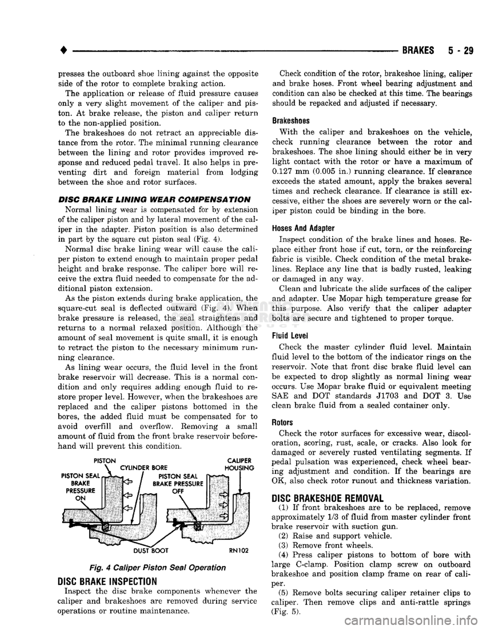
in part by the square cut piston seal (Fig. 4).
Normal disc brake lining wear will cause the cali
per piston to extend enough to maintain proper pedal height and brake response. The caliper bore will receive the extra fluid needed to compensate for the ad
ditional piston extension.
As the piston extends during brake application, the
square-cut seal is deflected outward (Fig. 4). When
brake pressure is released, the seal straightens and
returns to a normal relaxed position. Although the amount of seal movement is quite small, it is enough
to retract the piston to the necessary minimum run
ning clearance.
As lining wear occurs, the fluid level in the front
brake reservoir will decrease. This is a normal con dition and only requires adding enough fluid to restore proper level. However, when the brakeshoes are
replaced and the caliper pistons bottomed in the
bores,
the added fluid must be compensated for to avoid overfill and overflow. Removing a small
amount of fluid from the front brake reservoir before
hand will prevent this condition.
PISTON CALIPER
DUST BOOT
RN102
Fig.
4 Caliper
Piston
Seal
Operation
DISC
BRAKE INSPECTION
Inspect the disc brake components whenever the
caliper and brakeshoes are removed during service
operations or routine maintenance. Check condition of the rotor, brakeshoe lining, caliper
and brake hoses. Front wheel bearing adjustment and
condition can also be checked at this time. The bearings
should be repacked and adjusted if necessary.
Brakeshoes
With the caliper and brakeshoes on the vehicle,
check running clearance between the rotor and
brakeshoes. The shoe lining should either be in very light contact with the rotor or have a maximum of
0.127 mm (0.005 in.) running clearance. If clearance
exceeds the stated amount, apply the brakes several
times and recheck clearance. If clearance is still ex cessive, either the shoes are severely worn or the cal
iper piston could be binding in the bore.
Hoses
And Adapter Inspect condition of the brake lines and hoses. Re
place either front hose if cut, torn, or the reinforcing
fabric is visible. Check condition of the metal brake-
lines.
Replace any line that is badly rusted, leaking
or damaged in any way.
Clean and lubricate the slide surfaces of the caliper
and adapter. Use Mopar high temperature grease for
this purpose. Also verify that the caliper adapter
bolts are secure and tightened to proper torque.
Fluid Level Check the master cylinder fluid level. Maintain
fluid level to the bottom of the indicator rings on the
reservoir. Note that front disc brake fluid level can
be expected to drop slightly as normal lining wear occurs. Use Mopar brake fluid or equivalent meeting SAE and DOT standards J1703 and DOT 3. Use
clean brake fluid from a sealed container only.
Rotors
Check the rotor surfaces for excessive wear, discol
oration, scoring, rust, scale, or cracks. Also look for
damaged or severely rusted ventilating segments. If
pedal pulsation was experienced, check wheel bear ing adjustment and condition. If the bearings are OK, also check rotor runout and thickness variation.
DISC
BRAKESHOE
REMOVAL
(1) If front brakeshoes are to be replaced, remove
approximately 1/3 of fluid from master cylinder front
brake reservoir with suction gun. (2) Raise and support vehicle.
(3) Remove front wheels.
(4) Press caliper pistons to bottom of bore with
large C-clamp. Position clamp screw on outboard
brakeshoe and position clamp frame on rear of cali
per. (5) Remove bolts securing caliper retainer clips to
caliper. Then remove clips and anti-rattle springs (Fig. 5).
Page 226 of 1502
BRAKES
5 - 39
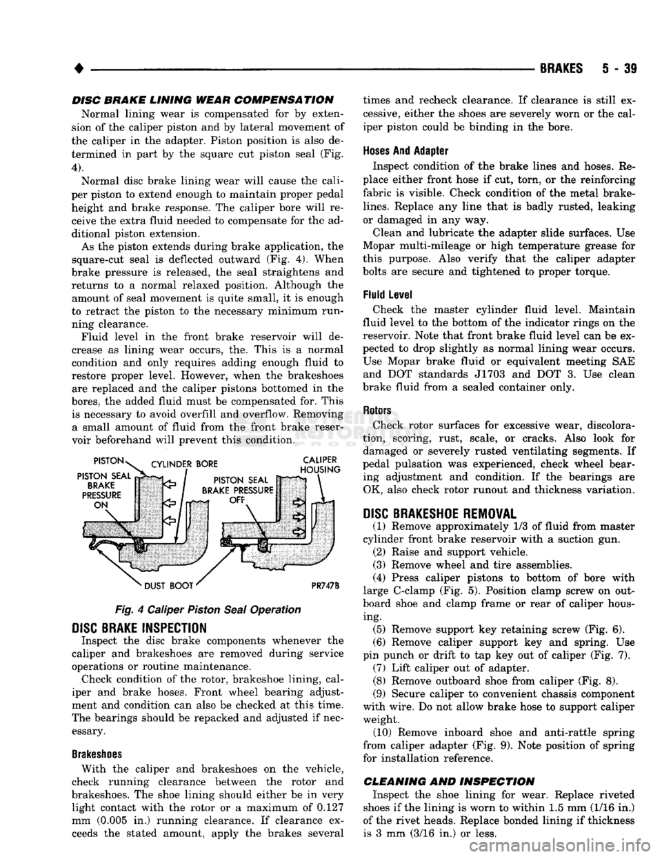
DISC BRAKE LINING WEAR COMPENSATION
Normal lining wear is compensated for by exten
sion of the caliper piston and by lateral movement of
the caliper in the adapter. Piston position is also de termined in part by the square cut piston seal (Fig.
4).
Normal disc brake lining wear will cause the cali
per piston to extend enough to maintain proper pedal height and brake response. The caliper bore will receive the extra fluid needed to compensate for the ad
ditional piston extension.
As the piston extends during brake application, the
square-cut seal is deflected outward (Fig. 4). When
brake pressure is released, the seal straightens and returns to a normal relaxed position. Although the amount of seal movement is quite small, it is enough
to retract the piston to the necessary minimum run ning clearance. Fluid level in the front brake reservoir will de
crease as lining wear occurs, the. This is a normal
condition and only requires adding enough fluid to
restore proper level. However, when the brakeshoes are replaced and the caliper pistons bottomed in the
bores,
the added fluid must be compensated for. This is necessary to avoid overfill and overflow. Removing a small amount of fluid from the front brake reser
voir beforehand will prevent this condition.
Fig.
4 Caliper
Piston
Seal
Operation
DISC
BRAKE INSPECTION
Inspect the disc brake components whenever the
caliper and brakeshoes are removed during service
operations or routine maintenance. Check condition of the rotor, brakeshoe lining, cal
iper and brake hoses. Front wheel bearing adjust
ment and condition can also be checked at this time.
The bearings should be repacked and adjusted if nec essary.
Brakeshoes
With the caliper and brakeshoes on the vehicle,
check running clearance between the rotor and
brakeshoes. The shoe lining should either be in very light contact with the rotor or a maximum of 0.127
mm (0.005 in.) running clearance. If clearance exceeds the stated amount, apply the brakes several times and recheck clearance. If clearance is still ex
cessive, either the shoes are severely worn or the cal
iper piston could be binding in the bore.
Hoses
And Adapter Inspect condition of the brake lines and hoses. Re
place either front hose if cut, torn, or the reinforcing
fabric is visible. Check condition of the metal brake-
lines.
Replace any line that is badly rusted, leaking
or damaged in any way.
Clean and lubricate the adapter slide surfaces. Use
Mopar multi-mileage or high temperature grease for
this purpose. Also verify that the caliper adapter
bolts are secure and tightened to proper torque.
Fluid Level Check the master cylinder fluid level. Maintain
fluid level to the bottom of the indicator rings on the
reservoir. Note that front brake fluid level can be ex
pected to drop slightly as normal lining wear occurs.
Use Mopar brake fluid or equivalent meeting SAE and DOT standards J1703 and DOT 3. Use clean
brake fluid from a sealed container only.
Rotors
Check rotor surfaces for excessive wear, discolora
tion, scoring, rust, scale, or cracks. Also look for damaged or severely rusted ventilating segments. If
pedal pulsation was experienced, check wheel bear ing adjustment and condition. If the bearings are OK, also check rotor runout and thickness variation.
DISC
BRAKESHOE REMOVAL
(1) Remove approximately 1/3 of fluid from master
cylinder front brake reservoir with a suction gun. (2) Raise and support vehicle.
(3) Remove wheel and tire assemblies.
(4) Press caliper pistons to bottom of bore with
large C-clamp (Fig. 5). Position clamp screw on out
board shoe and clamp frame or rear of caliper hous ing. (5) Remove support key retaining screw (Fig. 6).
(6) Remove caliper support key and spring. Use
pin punch or drift to tap key out of caliper (Fig. 7). (7) Lift caliper out of adapter. (8) Remove outboard shoe from caliper (Fig. 8).
(9) Secure caliper to convenient chassis component
with wire. Do not allow brake hose to support caliper weight. (10) Remove inboard shoe and anti-rattle spring
from caliper adapter (Fig. 9). Note position of spring
for installation reference.
CLEANING AND INSPECTION Inspect the shoe lining for wear. Replace riveted
shoes if the lining is worn to within 1.5 mm (1/16 in.)
of the rivet heads. Replace bonded lining if thickness is 3 mm (3/16 in.) or less.
Page 228 of 1502
•
BRAKES
5 - 41
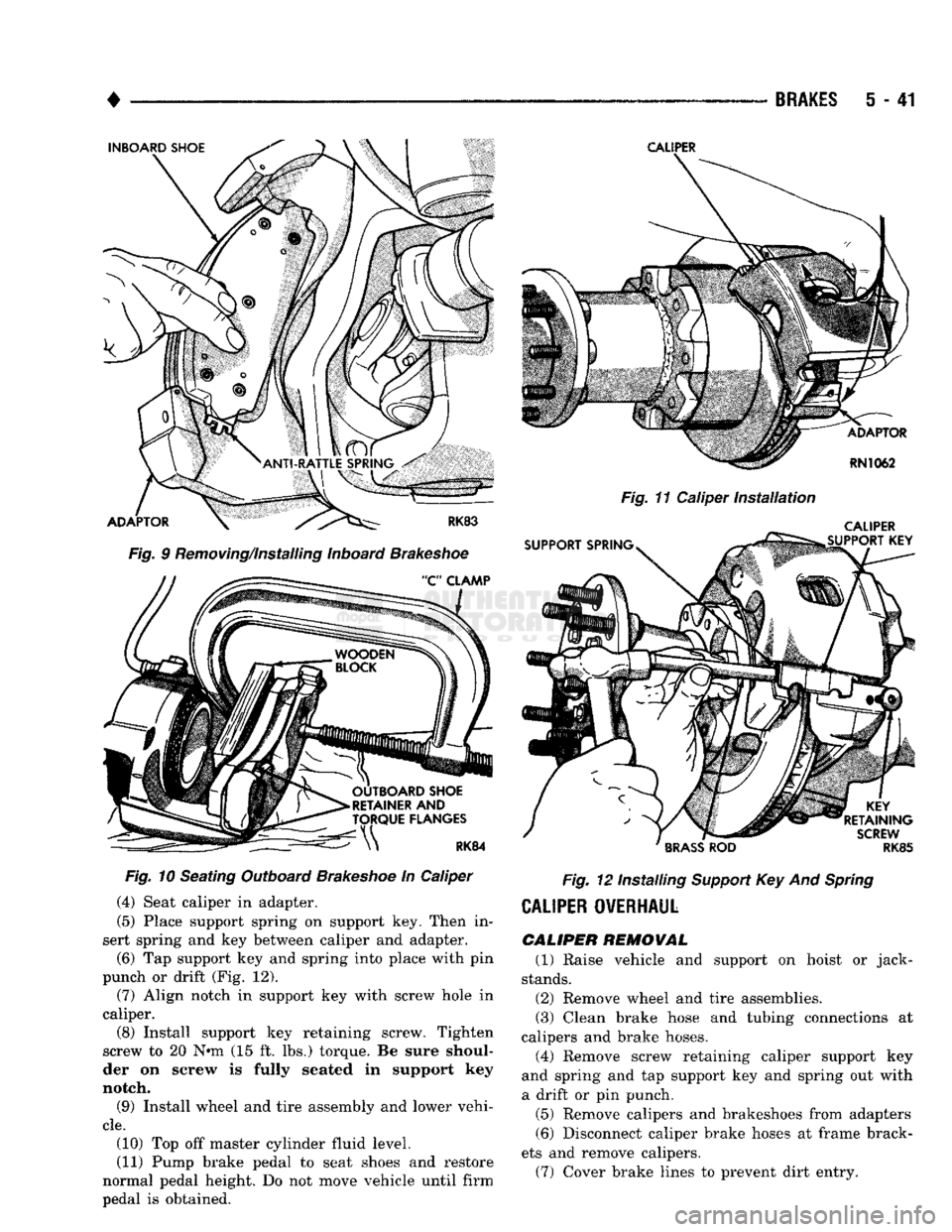
Fig.
9 Removing/Installing Inboard
Brakeshoe
Fig.
10 Seating Outboard
Brakeshoe
In Caliper (4) Seat caliper in adapter.
(5) Place support spring on support key. Then in
sert spring and key between caliper and adapter.
(6) Tap support key and spring into place with pin
punch or drift (Fig. 12). (7) Align notch in support key with screw hole in
caliper.
(8) Install support key retaining screw. Tighten
screw to 20 N»m (15 ft. lbs.) torque. Be sure shoul
der on screw is fully seated in support key
notch.
(9) Install wheel and tire assembly and lower vehi
cle.
(10) Top off master cylinder fluid level.
(11) Pump brake pedal to seat shoes and restore
normal pedal height. Do not move vehicle until firm
pedal is obtained.
CALIPER
Fig.
11 Caliper
Installation
CALIPER
Fig.
12 Installing
Support
Key And
Spring
CALIPER
OVERHAUL
CALIPER REMOVAL
(1) Raise vehicle and support on hoist or jack-
stands.
(2) Remove wheel and tire assemblies.
(3) Clean brake hose and tubing connections at
calipers and brake hoses.
(4) Remove screw retaining caliper support key
and spring and tap support key and spring out with
a drift or pin punch.
(5) Remove calipers and brakeshoes from adapters (6) Disconnect caliper brake hoses at frame brack
ets and remove calipers. (7) Cover brake lines to prevent dirt entry.
Page 260 of 1502
CLUTCH
6 - 7
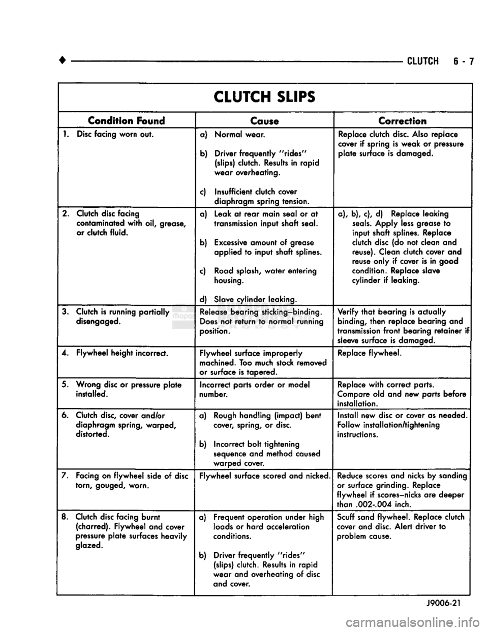
CLUTCH
SLIPS
Condition
Found
Cause
Correction
1.
Disc
facing
worn
out. a) Normal wear.
b) Driver
frequently
"rides"
(slips)
clutch. Results in rapid
wear overheating.
c) Insufficient clutch cover diaphragm spring tension. Replace clutch
disc.
Also
replace
cover if spring is weak or pressure
plate
surface is damaged.
2. Clutch disc facing contaminated
with
oil, grease,
or clutch fluid. a) Leak at
rear
main seal or at
transmission
input shaft seal.
b) Excessive amount of grease applied to input shaft splines.
c) Road
splash,
water
entering
housing.
d) Slave cylinder leaking. a), b), c), d) Replace leaking
seals.
Apply
less
grease to
input shaft splines. Replace
clutch disc (do not clean and reuse). Clean clutch cover and
reuse only if cover is in good
condition. Replace slave
cylinder if leaking.
3. Clutch is running
partially
disengaged.
Release
bearing sticking-binding.
Does
not
return
to normal running
position.
Verify
that
bearing is actually
binding,
then
replace bearing and
transmission
front
bearing
retainer
if sleeve surface is damaged.
4. Flywheel height incorrect. Flywheel surface improperly
machined. Too much stock removed
or surface is tapered. Replace flywheel.
5. Wrong disc or pressure
plate
installed. Incorrect parts order or model
number. Replace
with
correct parts.
Compare old and new parts before installation.
6. Clutch
disc,
cover and/or diaphragm spring, warped,
distorted. a)
Rough
handling (impact) bent
cover, spring, or
disc.
b) Incorrect bolt tightening sequence and method caused
warped cover. Install new disc or cover as needed.
Follow installation/tightening
instructions.
7. Facing on
flywheel
side of disc torn,
gouged,
worn. Flywheel surface scored and nicked.
Reduce
scores and nicks by sanding
or surface grinding. Replace
flywheel
if scores-nicks are deeper
than
.002-.004
inch.
8. Clutch disc facing burnt (charred). Flywheel and cover
pressure
plate
surfaces heavily
glazed.
a) Frequent operation under high
loads
or hard acceleration
conditions.
b) Driver
frequently
"rides"
(slips)
clutch. Results in rapid
wear and overheating of disc and cover.
Scuff
sand flywheel. Replace clutch
cover and
disc.
Alert driver to problem cause.
J9006-21