1993 DODGE TRUCK coolant temperature
[x] Cancel search: coolant temperaturePage 361 of 1502
8D
- 10
IGNITION
SYSTEMS
• Arcing at the tower will carbonize the cable boot,
which if it is connected to a new ignition coil, will cause the coil to fail. If the secondary coil cable shows any signs of dam
age,
it should be replaced with a new cable and new
terminal. Carbon tracking on the old cable can cause
arcing and the failure of a new ignition coil.
ENGINE
COOLANT
TEMPERATURE
SENSOR
TEST
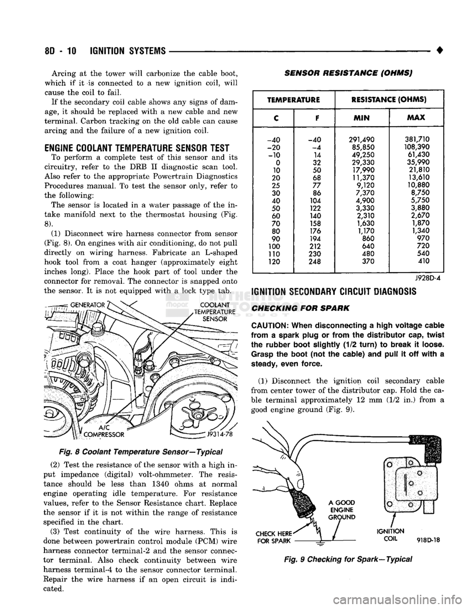
To perform a complete test of this sensor and its
circuitry, refer to the DRB II diagnostic scan tool.
Also refer to the appropriate Powertrain Diagnostics
Procedures manual. To test the sensor only, refer to
the following: The sensor is located in a water passage of the in
take manifold next to the thermostat housing (Fig.
8).
(1) Disconnect wire harness connector from sensor
(Fig. 8). On engines with air conditioning, do not pull
directly on wiring harness. Fabricate an L-shaped
hook tool from a coat hanger (approximately eight inches long). Place the hook part of tool under the
connector for removal. The connector is snapped onto
the sensor. It is not equipped with a lock type tab.
COOLANT
TEMPERATURE
SENSOR
SENSOR RESISTANCE (OHMSJ
V
J9314-78
Fig. 8 Coolant Temperature Sensor—Typical (2) Test the resistance of the sensor with a high in
put impedance (digital) volt-ohmmeter. The resis tance should be less than 1340 ohms at normal
engine operating idle temperature. For resistance
values, refer to the Sensor Resistance chart. Replace
the sensor if it is not within the range of resistance specified in the chart.
(3) Test continuity of the wire harness. This is
done between powertrain control module (PCM) wire
harness connector terminal-2 and the sensor connec
tor terminal. Also check continuity between wire harness terminal-4 to the sensor connector terminal. Repair the wire harness if an open circuit is indi
cated.
TEMPERATURE
RESISTANCE
(OHMS)
C
F
MIN
MAX
-40 -40 291,490 381,710
-20
-4
85,850
108,390
-10 14
49,250 61,430
0
32 29,330
35,990
10 50 17,990 21,810
20 68 11,370 13,610
25
77 9,120 10,880
30 86
7,370
8,750
40 104
4,900
5,750
50 122
3,330 3,880
60 140 2,310
2,670
70 158
1,630 1,870
80 176
1,170 1,340
90 194
860
970
100 212 640
720
110 230 480 540
120 248 370 410
J928D-4
IGNITION
SECONDARY
CIRCUIT
DIAGNOSIS
CHECKING FOR SPARK
CAUTION:
When
disconnecting a
high
voltage
cable
from
a spark
plug
or
from
the
distributor
cap,
twist
the rubber
boot
slightly
(1/2
turn)
to
break
it
loose.
Grasp
the
boot
(not the cable) and
pull
it off
with
a
steady,
even force.
(1) Disconnect the ignition coil secondary cable
from center tower of the distributor cap. Hold the ca
ble terminal approximately 12 mm (1/2 in.) from a good engine ground (Fig. 9).
CHECK
HERE
FOR
SPARK
IGNITION
COIL
918D-18
Fig. 9 Checking for Spark—Typical
Page 369 of 1502
8D
- 18
IGNITION
SYSTEMS
•
COMPONENT REMGWAL/INSTALLATION
INDEX
page
Automatic
Shut Down (ASD) Relay
18
Camshaft
Position
Sensor
, 18
Crankshaft Position
Sensor
18
Distributor
Service
20
Engine
Coolant Temperature
Sensor
20
General
Information
18
Ignition
Coil
21
page
Intake
Manifold Charge
Air
Temperature
Sensor
. 22
Manifold Absolute Pressure (MAP)
Sensor
..... 22
Oxygen
(02)
Sensor
22
Powertrain
Control
Module (PCM)
22
Spark
Plug Secondary Cables
24
Spark
Plugs
23
Throttle
Position
Sensor
(TPS)
24
GENERAL
INFORMATION
This section
of the
group, Component Removal/In
stallation, will discuss
the
removal
and
installation
of ignition system components. For basic ignition system diagnostics
and
service
adjustments, refer
to the
Diagnostics/Service Proce
dures section
of
this group. For system operation
and
component identification,
refer
to the
Component Identification/System Opera
tion section
of
this group.
AUTOMATIC
SHUT DOWN
(ASb)
RELAY
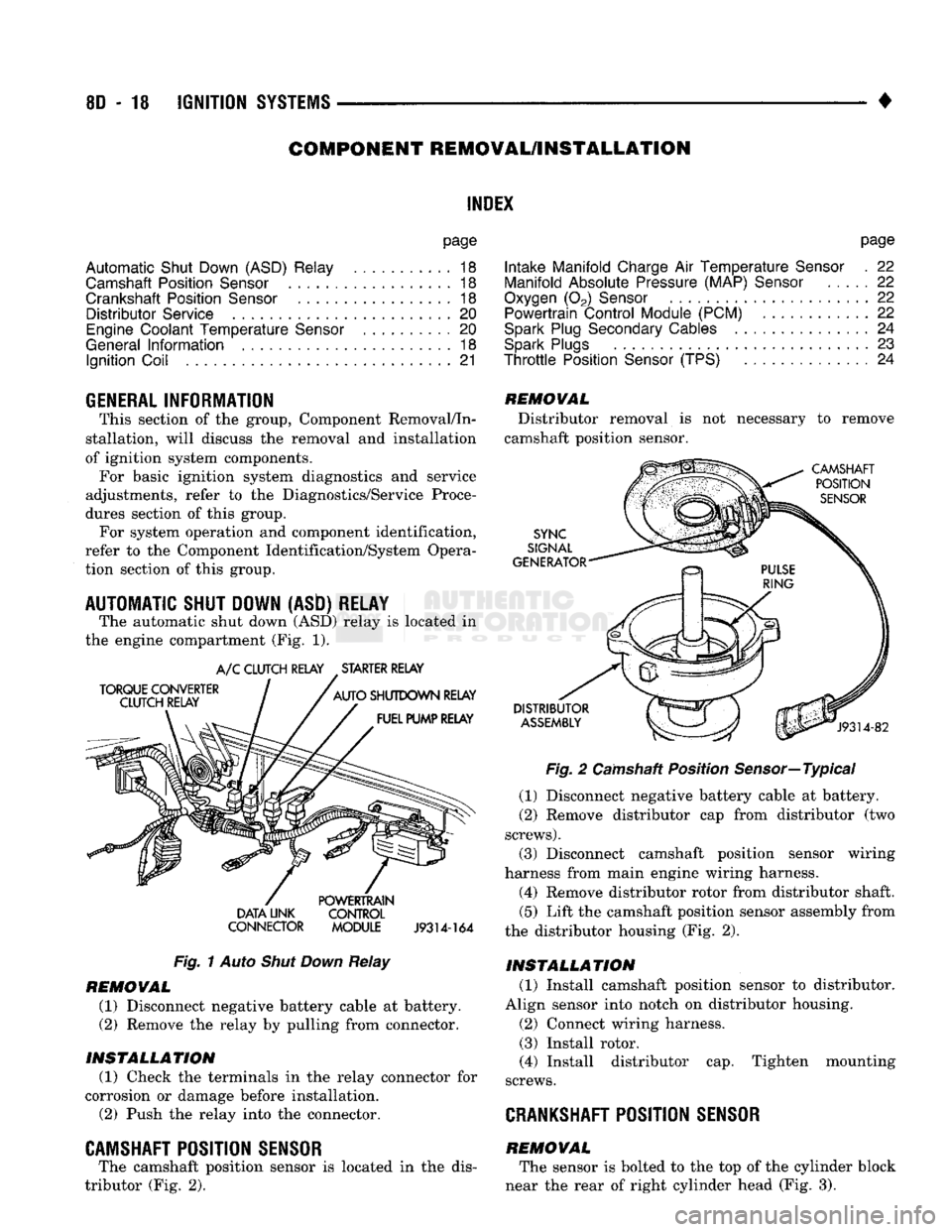
The automatic shut down
(ASD)
relay
is
located
in
the engine compartment
(Fig. 1).
TORQUE CONVERTER
CLUTCH RELAY
A/C
CLUTCH RELAY STARTER RELAY
AUTO
SHUTDOWN RELAY FUEL PUMP RELAY DATA UNK
CONNECTOR POWERTRAIN
CONTROL
MODULE
J9314-164
Fig.
1
Auto
Shut Down
Relay
REMOVAL
(1) Disconnect negative battery cable
at
battery.
(2)
Remove
the
relay
by
pulling from connector.
INSTALLATION
(1) Check
the
terminals
in the
relay connector
for
corrosion
or
damage before installation.
(2)
Push
the
relay into
the
connector.
CAMSHAFT POSITION SENSOR
The camshaft position sensor
is
located
in the
dis
tributor
(Fig. 2).
REMOVAL
Distributor removal
is not
necessary
to
remove
camshaft position sensor.
CAMSHAFT POSITION
SENSOR
SYNC
SIGNAL
GENERATOR
DISTRIBUTOR
ASSEMBLY
J9314-82
Fig.
2
Camshaft Position Sensor—Typical
(1) Disconnect negative battery cable
at
battery.
(2)
Remove distributor
cap
from distributor
(two
screws).
(3) Disconnect camshaft position sensor wiring
harness from main engine wiring harness.
(4) Remove distributor rotor from distributor shaft.
(5)
Lift
the
camshaft position sensor assembly from
the distributor housing
(Fig. 2).
INSTALLATION
(1) Install camshaft position sensor
to
distributor.
Align sensor into notch
on
distributor housing.
(2)
Connect wiring harness.
(3) Install rotor.
(4) Install distributor
cap.
Tighten mounting
screws.
CRANKSHAFT
POSITION SENSOR
REMOVAL The sensor
is
bolted
to the top of the
cylinder block
near
the
rear
of
right cylinder head
(Fig. 3).
Page 371 of 1502
8D
- 20
IGNITION
SYSTEMS
•
ENGINE
COOLANT
TEMPERATURE
SENSOR
WARNING: HOT, PRESSURIZED COOLANT CAN CAUSE INJURY BY SCALDING. COOLING SYSTEM MUST BE PARTIALLY DRAINED BEFORE REMOV
ING THE COOLANT TEMPERATURE SENSOR. RE
FER TO GROUP 7, COOLING.
REMOVAL
(1) Partially drain cooling system. Refer to Group
7, Cooling.
(2)
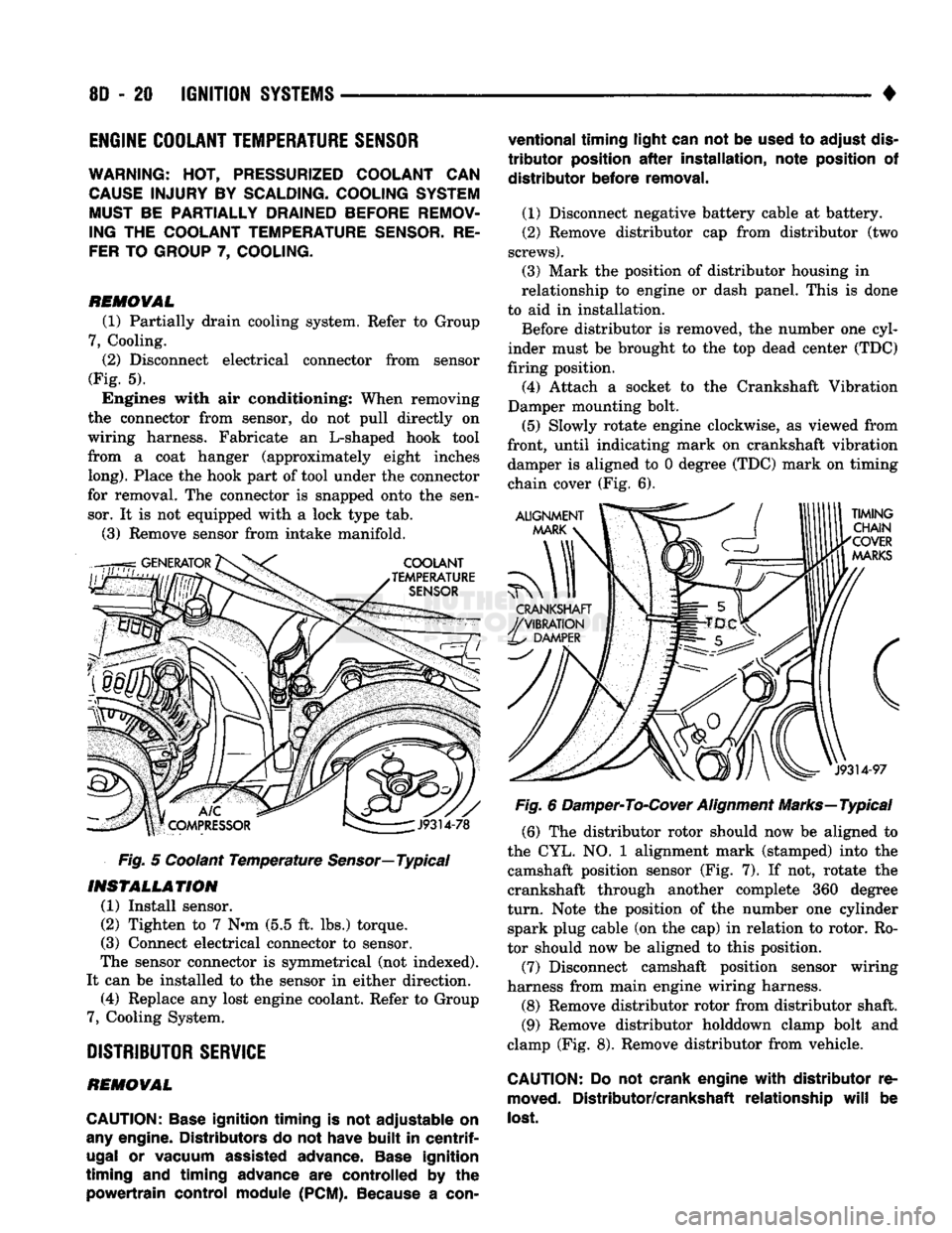
Disconnect electrical connector from sensor
(Fig. 5). Engines with air conditioning: When removing
the connector from sensor, do not pull directly on
wiring harness. Fabricate an L-shaped hook tool
from a coat hanger (approximately eight inches
long).
Place the hook part of tool under the connector
for removal. The connector is snapped onto the sen sor. It is not equipped with a lock type tab.
(3) Remove sensor from intake manifold.
Fig. 5 Coolant Temperature
Sensor—
Typical
INSTALLATION
(1) Install sensor.
(2) Tighten to 7 Nnn (5.5 ft. lbs.) torque.
(3) Connect electrical connector to sensor.
The sensor connector is symmetrical (not indexed).
It can be installed to the sensor in either direction. (4) Replace any lost engine coolant. Refer to Group
7, Cooling System.
DISTRIBUTOR
SERVICE
REMOVAL
CAUTION:
Base
ignition timing
is not
adjustable
on
any
engine. Distributors
do not
have
built
in
centrif
ugal
or
vacuum assisted advance.
Base
ignition
timing
and
timing advance
are
controlled
by the
powertrain control module
(PCM).
Because
a
con
ventional timing light can
not be
used
to
adjust
dis
tributor
position
after
installation, note position
of
distributor before removal.
(1) Disconnect negative battery cable at battery.
(2) Remove distributor cap from distributor (two
screws).
(3) Mark the position of distributor housing in
relationship to engine or dash panel. This is done
to aid in installation. Before distributor is removed, the number one cyl
inder must be brought to the top dead center (TDC)
firing position. (4) Attach a socket to the Crankshaft Vibration
Damper mounting bolt.
(5) Slowly rotate engine clockwise, as viewed from
front, until indicating mark on crankshaft vibration damper is aligned to 0 degree (TDC) mark on timing
chain cover (Fig. 6).
Fig. 6 Damper-To-Cover Alignment Marks—Typical (6) The distributor rotor should now be aligned to
the CYL. NO. 1 alignment mark (stamped) into the camshaft position sensor (Fig. 7). If not, rotate the
crankshaft through another complete 360 degree
turn.
Note the position of the number one cylinder spark plug cable (on the cap) in relation to rotor. Ro
tor should now be aligned to this position.
(7) Disconnect camshaft position sensor wiring
harness from main engine wiring harness.
(8) Remove distributor rotor from distributor shaft. (9) Remove distributor holddown clamp bolt and
clamp (Fig. 8). Remove distributor from vehicle.
CAUTION: Do not
crank engine
with
distributor
re
moved.
Distributor/crankshaft relationship
will
be
lost.
Page 382 of 1502
• • ^ ^ ^ INSTRUMENT PANEL AND GAUGES 8E - 1
CONTENTS
page
CLUSTER AND GAUGE SERVICE PROCEDURES . 12
CLUSTER AND GAUGE TEST PROCEDURES .. i
GENERAL INFORMATION . 1
page
MESSAGE CENTER-DIESEL ENGINE ........ 4
MESSAGE CENTER-GAS ENGINE .......... 3
SWITCH
AND PANEL COMPONENT SERVICE . 16
GENERAL
INFORMATION
INDEX
page
Generator
Indicating
System
2
Distance
Sensor
2
Electronic
Digital
Clock
3
Fuel
Level
Indicating
System
1
page
Malfunction
Indicator
(Check
Engine)
3
Oil
Pressure
Warning
Lamp
................. 2
Speedometer/Odometer
System
2
Temperature
and Oil
Indicating
System
......... 2
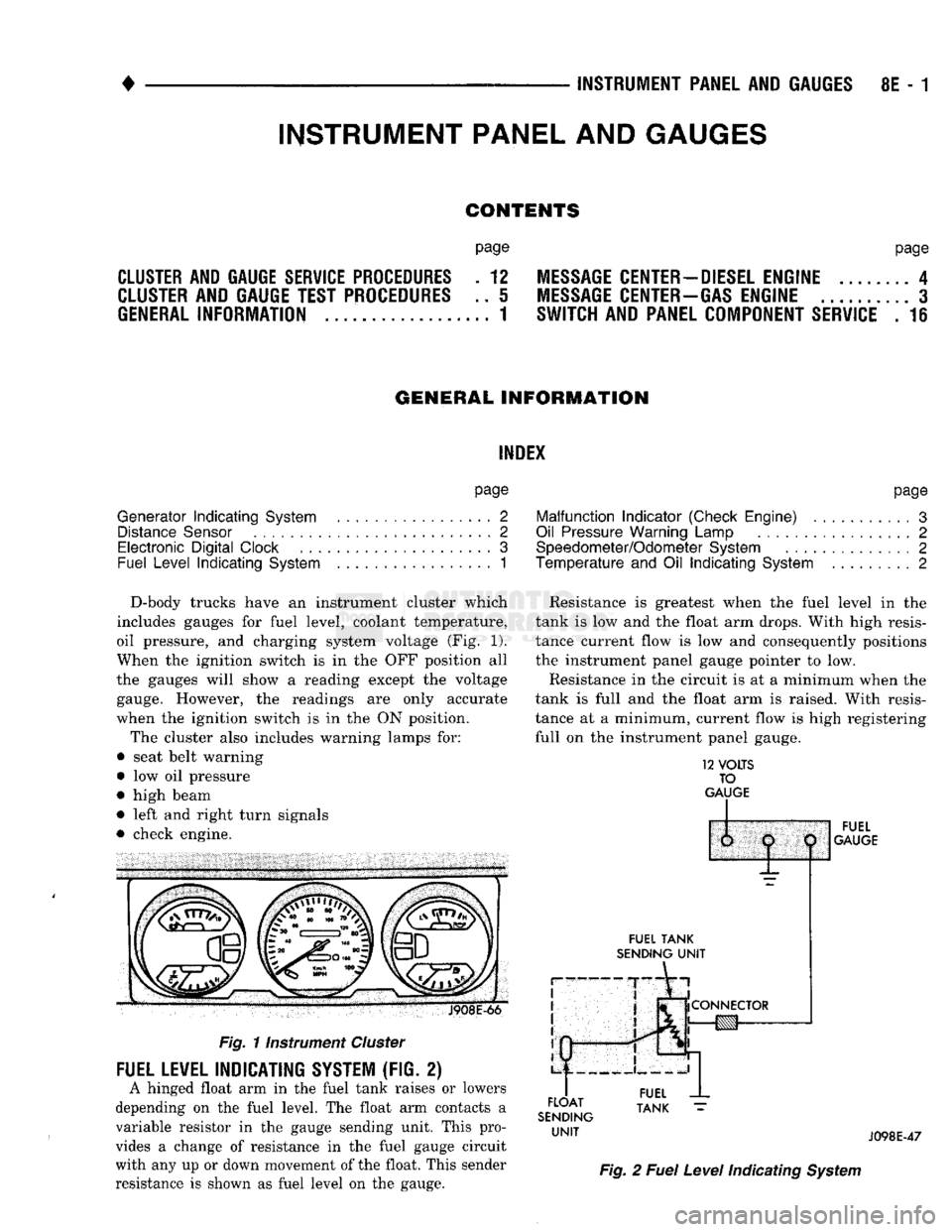
D-body trucks have an instrument cluster which
includes gauges for fuel level, coolant temperature,
oil pressure, and charging system voltage (Fig. 1).
When the ignition switch is in the OFF position all
the gauges will show a reading except the voltage gauge. However, the readings are only accurate
when the ignition switch is in the ON position.
The cluster also includes warning lamps for:
• seat belt warning
• low oil pressure
• high beam
• left and right turn signals
• check engine. J908E-66
Fig.
11nstrument
Cluster
FUEL LEVEL INDICATING SYSTEM (FIG. 2)
A hinged float arm in the fuel tank raises or lowers
depending on the fuel level. The float arm contacts a
variable resistor in the gauge sending unit. This pro
vides a change of resistance in the fuel gauge circuit
with any up or down movement of the float. This sender
resistance is shown as fuel level on the gauge. Resistance is greatest when the fuel level in the
tank is low and the float arm drops. With high resis
tance current flow is low and consequently positions
the instrument panel gauge pointer to low.
Resistance in the circuit is at a minimum when the
tank is full and the float arm is raised. With resis
tance at a minimum, current flow is high registering
full on the instrument panel gauge.
12
VOLTS
TO
GAUGE
IP
FUEL
TANK
SENDING
UNIT
FLOAT
SENDING
UNIT
1:
1
j
^
fCONNECTOR
!g|yj-»—
FUEL
GAUGE
FUEL
TANK
J098E-47
Fig.
2
Fuel
Level
Indicating
System
INSTRUMENT PANEL AND GAUGES
Page 383 of 1502
8E
- 2
INSTRUMENT PANEL
AND
GAUGES
•
TEMPERATURE AND
OIL
INDICATING SYSTEM
(FIG.
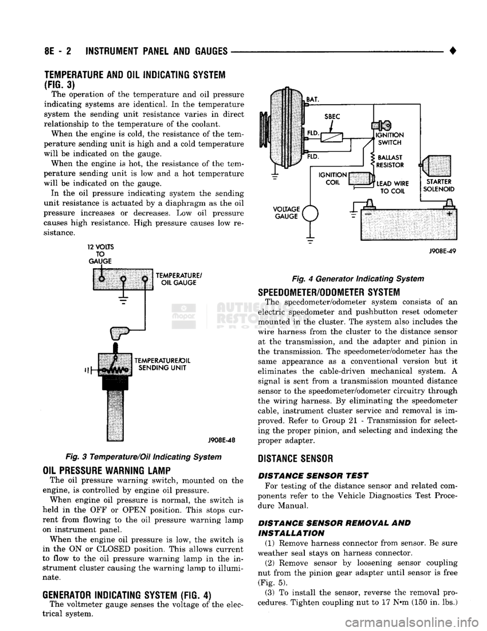
3) The operation of the temperature and oil pressure
indicating systems are identical. In the temperature
system the sending unit resistance varies in direct
relationship to the temperature of the coolant. When the engine is cold, the resistance of the tem
perature sending unit is high and a cold temperature
will be indicated on the gauge. When the engine is hot, the resistance of the tem
perature sending unit is low and a hot temperature
will be indicated on the gauge. In the oil pressure indicating system the sending
unit resistance is actuated by a diaphragm as the oil
pressure increases or decreases. Low oil pressure causes high resistance. High pressure causes low re
sistance. 12
VOLTS
TO
GAUGE
TEMPERATURE/
OIL GAUGE
TEMPERATURE/OIL SENDING
UNIT
J908E-48
Fig. 3 Temperature/Oil indicating System
OIL
PRESSURE
WARNING LAMP
The oil pressure warning switch, mounted on the
engine, is controlled by engine oil pressure. When engine oil pressure is normal, the switch is
held in the OFF or OPEN position. This stops cur
rent from flowing to the oil pressure warning lamp
on instrument panel. When the engine oil pressure is low, the switch is
in the ON or CLOSED position. This allows current
to flow to the oil pressure warning lamp in the in strument cluster causing the warning lamp to illumi
nate.
GENERATOR
INDICATING
SYSTEM
(FIG. 4)
The voltmeter gauge senses the voltage of the elec
trical system.
VOLTAGE
/*
GAUGE
P/
J908E-49 Fig. 4 Generator Indicating System
SPEEDOMETER/ODOMETER SYSTEM
The speedometer/odometer system consists of an
electric speedometer and pushbutton reset odometer
mounted in the cluster. The system also includes the
wire harness from the cluster to the distance sensor at the transmission, and the adapter and pinion in
the transmission. The speedometer/odometer has the same appearance as a conventional version but it
eliminates the cable-driven mechanical system. A signal is sent from a transmission mounted distance
sensor to the speedometer/odometer circuitry through
the wiring harness. By eliminating the speedometer cable, instrument cluster service and removal is im
proved. Refer to Group 21 - Transmission for select ing the proper pinion, and selecting and indexing the
proper adapter.
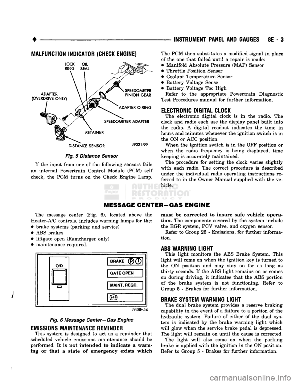
DISTANCE
SENSOR
DISTANCE SENSOR TEST For testing of the distance sensor and related com
ponents refer to the Vehicle Diagnostics Test Proce dure Manual.
DISTANCE SENSOR REMOVAL AND INSTALLATION (1) Remove harness connector from sensor. Be sure
weather seal stays on harness connector. (2) Remove sensor by loosening sensor coupling
nut from the pinion gear adapter until sensor is free (Fig. 5).
(3) To install the sensor, reverse the removal pro
cedures. Tighten coupling nut to 17 N»m (150 in. lbs.)
Page 384 of 1502
•
INSTRUMENT PANEL
AND
GAUGES
8E - 3
MALFUNCTION INDICATOR (CHECK ENGINE)
Fig.
5
Distance Sensor
If
the
input from
one of the
following sensors fails
an internal Powertrain Control Module
(PCM)
self
check,
the PCM
turns
on the
Check Engine Lamp. The
PCM
then substitutes
a
modified signal
in
place
of
the one
that failed until
a
repair
is
made:
• Manifold Absolute Pressure (MAP) Sensor
• Throttle Position Sensor
• Coolant Temperature Sensor
• Battery Voltage Sense
• Battery Voltage
Too
High
Refer
to the
appropriate Powertrain Diagnostic
Test Procedures manual
for
further information.
ELECTRONIC DIGITAL CLOCK
The electronic digital clock
is in the
radio.
The
clock
and
radio each
use the
display panel built into
the radio.
A
digital readout indicates
the
time
in
hours
and
minutes whenever
the
ignition switch
is in
the
ON or ACC
position. When
the
ignition switch
is in the OFF
position
or
when
the
radio frequency
is
being displayed, time keeping
is
accurately maintained. The procedure
for
setting
the
clock varies slightly
with each radio.
The
correct procedure
is
described under
the
individual radio operating instructions
re
ferred
to in the
Owner Manual supplied with
the ve
hicle.
MESSAGE CENTER—GAS ENGINE
The message center
(Fig. 6),
located above
the
Heater-A/C controls, includes warning lamps
for the:
• brake systems (parking
and
service)
•
ABS
brakes • liftgate open (Ramcharger only)
• maintenance required.
O/D
BRAKE
(P)(7
GATE OPEN
MAINT
REQD.
J938E-54
Fig.
6
Message Center—Gas Engine
EMISSIONS
MAINTENANCE REMINDER
This system
is
designed
to act as a
reminder that
scheduled vehicle emissions maintenance should
be
performed.
It is not
intended
to
indicate
a
warn
ing
or
that
a
state
of
emergency exists which must
be
corrected
to
insure safe vehicle opera
tion.
The
components covered
by the
system include
the
EGR
system,
PCV
valve,
and
oxygen sensor. Refer
to
Group
25 -
Emissions,
for
further informa
tion.
ABS
WARNING
LIGHT
This light monitors
the ABS
Brake System. This
light will come
on
when
the
ignition
key is
turned
to
the
ON
position
and may
stay
on for as
long
as
thirty seconds.
If the ABS
light remains
on or
comes on during driving,
it
indicates that
the ABS
portion
of
the
brake system
is not
functioning. Refer
to
Group
5 -
Brakes
for
further information.
BRAKE
SYSTEM WARNING
LIGHT
The dual brake system provides
a
reserve braking
capability
in the
event
of a
failure
to a
portion
of the
hydraulic system. Failure
of
either
of the
dual sys
tem
is
indicated
by the
brake warning light which
will glow when
the
service brake pedal
is
depressed.
The light will remain
on
until
the
cause
is
corrected. The light will also come
on
when
the
parking
brake
is
applied with
the
ignition
in the ON
position.
Refer
to
Group
5 -
Brakes
for
further information.
Page 390 of 1502
INSTRUMENT
PANEL
AND
GAUGES
8E - S
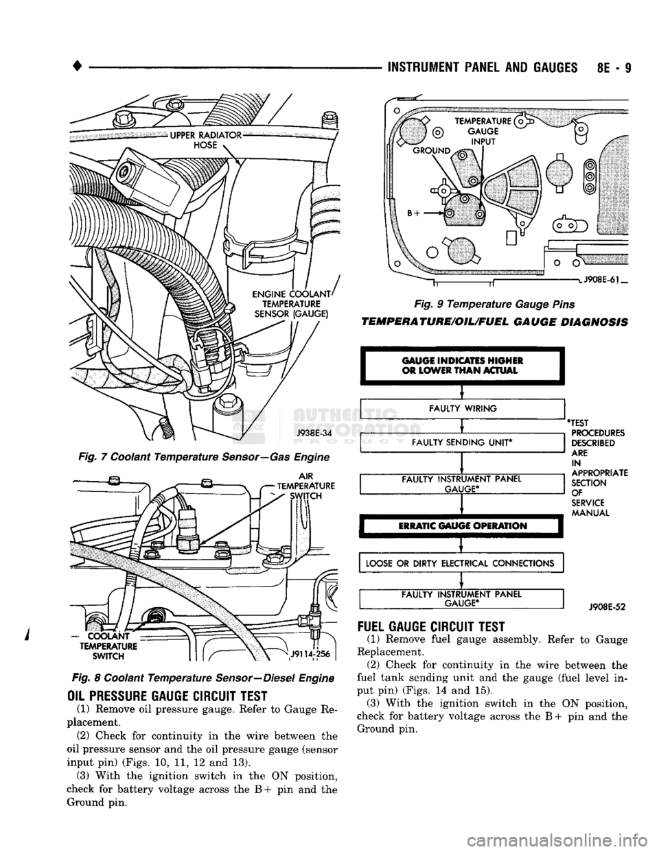
J938E-34
Fig. 7 Coolant Temperature Sensor—Gas Engine
AIR
TEMPERATURE SWITCH
-
COOLANT TEMPERATURE
SWITCH
Fig. 8 Coolant Temperature Sensor—Diesel Engine
OIL PRESSURE
GAUGE
CIRCUIT
TEST
(1) Remove oil pressure gauge. Refer to Gauge Re
placement. (2) Check for continuity in the wire between the
oil pressure sensor and the oil pressure gauge (sensor
input pin) (Figs. 10, 11, 12 and 13). (3) With the ignition switch in the ON position,
check for battery voltage across the B+ pin and the Ground pin. J908E-6i_
Fig. 9 Temperature Gauge Pins
TEMPERATURE/OIL/FUEL
GAUGE
DIAGNOSIS
GAUGE INDICATES HIGHER
OR
LOWER
THAN
ACTUAL I
FAULTY WIRING
FAULTY SENDING
UNIT*
FAULTY INSTRUMENT PANEL
GAUGE*
ERRATIC
GAUGE OPERATION
'TEST
PROCEDURES
DESCRIBED
ARE
IN
APPROPRIATE
SECTION OF
SERVICE
MANUAL
LOOSE
OR DIRTY ELECTRICAL CONNECTIONS FAULTY INSTRUMENT PANEL
GAUGE*
J908E-52
FUEL
GAUGE
CIRCUIT
TEST
(1) Remove fuel gauge assembly. Refer to Gauge
Replacement. (2) Check for continuity in the wire between the
fuel tank sending unit and the gauge (fuel level in
put pin) (Figs. 14 and 15). (3) With the ignition switch in the ON position,
check for battery voltage across the B + pin and the Ground pin.
Page 501 of 1502
FUEL
INJECTOR
#6
FUEL
INJECTOR
#4
FUEL
INJECTOR
#2
BEYOND
THIS
POINT
SEE
VIEW
Z
EGR
SOLENOID/
TRANSDUCER
ASSEMBLY
A/C
COMPRESSOR
CLUTCH
GENERATOR
GROUND
POWER
STEERING
PUMP
AAAP
SENSOR
THROTTLE
EVAP/
POSITION
PURGE
(SENSOR)
SOLENOID IDLE
AIR
CONTROL MOTOR
TO
A/C
COMPRESSOR
CLUTCH
DISTRIBUTOR
IGNITION
COIL
ENGINE
COOLANT
TEMPERATURE
ENGINE
COOLANT
SENSOR
(PCM)
TEMPERATURE
SENSOR
(GAUGE)
ENGINE
OIL
PRESSURE
SENDING
UNIT/
SWITCH
DISTRIBUTOR
CONNER ,NJECTOR#1
INJECTOR
#3
VIEW
IN
DIRECTION OF ARROW
1
FUEL
INJECTOR
#5
TO
'TRANSMISSION
WIRING
J938W-85 INS
m
a
o
>
o
>
2
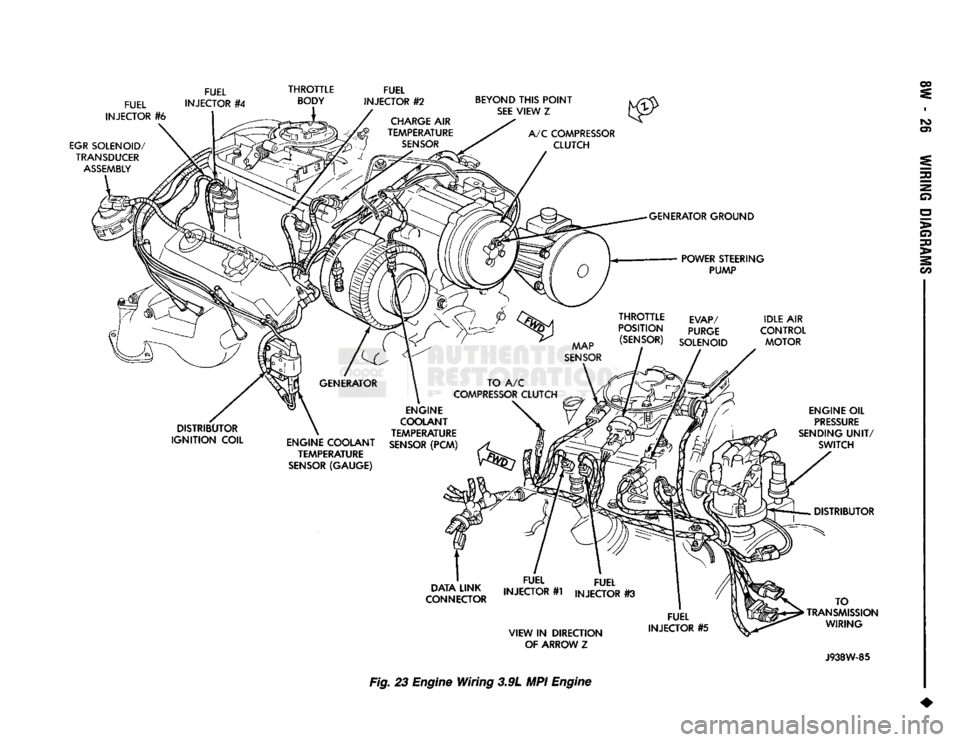
m Fig. 23 Engine
Wiring
3.9L MPI Engine