1993 DODGE TRUCK coolant temperature
[x] Cancel search: coolant temperaturePage 298 of 1502
•
COOLING
SYSTEM
7 - 27 down to -67.7°C (-90°F). A higher percentage will
freeze at a warmer temperature. Also, a higher per centage of antifreeze can cause the engine to over
heat because specific heat of antifreeze is lower than
that of water.
CAUTION:
Richer
antifreeze
mixtures
cannot
be
measured
with
normal
field
equipment
and can
cause
problems
associated
with 100
percent
ethyl
ene-glycol.
COOLANT SELECTION-ADDITIVES The presence of aluminum components in the cool
ing system requires strict corrosion protection. Main
tain coolant at specified level with a mixture of ethylene-glycol based antifreeze and water. Only use an antifreeze containing ALUGARD 340-2
™
such as
Mopar Antifreeze. If coolant becomes contaminated
or looses color, drain and flush cooling system and
fill with correctly mixed solution.
A 0.25 percent emulsifiable oil is added to the ra
diator at the factory to prevent solder corrosion.
CAUTION:
Do not use
coolant
additives
that are
claimed
to
improve
engine
cooling.
COOLANT SERVICE-EXCEPT DIESEL It is recommended that the cooling system be
drained and flushed at 84,000 kilometers (52,500
miles) or 3 years, whichever occurs first. Then every
two years or 48,000 kilometers (30,000 miles), which ever occurs first.
COOLANT SERVICE-DIESEL ENGINE It is recommended that the cooling system be
drained and flushed every 24 months or 38,600 kilo meters (24,000 miles), whichever occurs first.
COOLANT LEVEL CHECK-ROUTINE Do not remove radiator cap for routine coolant
level inspections. The coolant level can be checked at the coolant reserve/overflow tank.
The coolant reserve/overflow system provides a
quick visual method for determining the coolant
level without removing the radiator pressure cap.
With engine idling and at normal operating temper ature, observe coolant level in coolant reserve/over
flow tank. The coolant level should be between the MIN and MAX (diesel engine) or ADD and FULL (gas engines) marks.
ADDING ADDITIONAL COOLANT-ROUTINE Do not remove the radiator cap to add coolant
to the system. When adding coolant to maintain the correct level, do so at the coolant reserve/overflow
tank with a 50/50 mixture of ethylene-glycol anti
freeze (containing Alugard 340-2 ™) and water. Re move the radiator cap only for testing or when
refilling the system after service. Removing cap un necessarily can cause loss of coolant and allow air to
enter system. This produces corrosion.
COOLANT LEVEL CHECK-SERVICE The cooling system is closed and designed to main
tain coolant level to the top of the radiator.
WARNING:
DO
NOT OPEN RADIATOR DRAINCOCK
WITH
ENGINE RUNNING
OR
WHILE ENGINE
IS HOT
AND COOLING
SYSTEM
IS
UNDER
PRESSURE.
When vehicle servicing requires a coolant level
check in the radiator, drain several ounces of coolant
from the radiator drain cock. Do this while observing
the coolant reserve/overflow system tank. The cool ant level in the reserve/overflow tank should drop
slightly. If not, inspect for a leak between radiator and coolant reserve/overflow system connection. Re
move radiator cap. The coolant level should be to the
top of the radiator. If not and if coolant level in re serve/overflow tank is at the ADD (gas engines) or
MIN (5.9L diesel engine) mark, check for:
• An air leak in the coolant reserve/overflow tank
• An air leak in the radiator filler neck
• Leak in the pressure cap seal to the radiator filler
neck
LOW COOLANT LEVEL-AERATION If the coolant level in the radiator drops below the
top of the radiator core tubes, air will enter the sys
tem. Low coolant level can cause the thermostat pellet
to be suspended in air instead of coolant. This will cause the thermostat to open later, which in turn causes higher coolant temperature. Air trapped in
cooling system also reduces the amount of coolant
circulating in the heater core. This may result in low
heat output.
DEAERATION As the engine operates, air trapped in the cooling
system gathers under the radiator cap. The next time
engine is operated, thermal expansion of coolant will
push trapped air past radiator cap into coolant re serve/overflow tank. Here it escapes to atmosphere in
the tank. When engine cools down the coolant, it will
be drawn from reserve/overflow tank into radiator to replace removed air.
DRAINING
COOLING
SYSTEM
WARNING:
DO NOT
REMOVE
THE
CYLINDER BLOCK DRAIN PLUGS
OR
LOOSEN THE RADIATOR
DRAIN PLUG
WITH
SYSTEM
HOT AND
UNDER
PRESSURE.
SERIOUS BURNS
FROM
COOLANT
CAN OCCUR.
Page 299 of 1502
7 - 28
COOLING SYSTEM
DO NOT WASTE reusable coolant. If the solution
is clean, drain the coolant into a clean container for
reuse.
(1) Start the engine and place the heater control
temperature selector in the Full On position. Engine vacuum is needed to actuate the heater controls.
(2) Turn the ignition off. (3) Do not remove radiator cap when draining cool
ant from reserve/overflow tank. Open radiator drain
plug and when tank is empty, remove radiator cap. If
the coolant reserve/overflow tank does not drain, re fer to the Testing Cooling System for Leaks section
in this group. The coolant need not be removed from
tank unless the system is being refilled with fresh mixture.
(4) On vehicles equipped with gas powered en
gines,
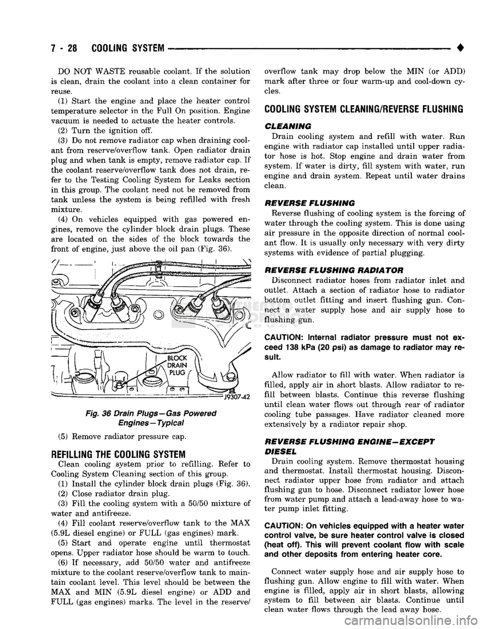
remove the cylinder block drain plugs. These are located on the sides of the block towards the
front of engine, just above the oil pan (Fig. 36).
Fig.
36 Drain Plugs—Gas Powered
Engines—Typical
(5) Remove radiator pressure cap.
REFILLING
THE
COOLING SYSTEM
Clean cooling system prior to refilling. Refer to
Cooling System Cleaning section of this group. (1) Install the cylinder block drain plugs (Fig. 36).
(2)
Close radiator drain plug.
(3) Fill the cooling system with a 50/50 mixture of
water and antifreeze. (4) Fill coolant reserve/overflow tank to the MAX
(5.9L diesel engine) or FULL (gas engines) mark. (5) Start and operate engine until thermostat
opens. Upper radiator hose should be warm to touch. (6) If necessary, add 50/50 water and antifreeze
mixture to the coolant reserve/overflow tank to main
tain coolant level. This level should be between the MAX and MIN (5.9L diesel engine) or ADD and FULL (gas engines) marks. The level in the reserve/ overflow tank may drop below the MIN (or ADD)
mark after three or four warm-up and cool-down cy
cles.
COOLING SYSTEM CLEANING/REVERSE FLUSHING
CLEMMING Drain cooling system and refill with water. Run
engine with radiator cap installed until upper radia
tor hose is hot. Stop engine and drain water from system. If water is dirty, fill system with water, run
engine and drain system. Repeat until water drains
clean.
REVERSE
FLUSHING
Reverse flushing of cooling system is the forcing of
water through the cooling system. This is done using air pressure in the opposite direction of normal cool
ant flow. It is usually only necessary with very dirty
systems with evidence of partial plugging.
REVERSE
FLUSHING
RADIATOR Disconnect radiator hoses from radiator inlet and
outlet. Attach a section of radiator hose to radiator
bottom outlet fitting and insert flushing gun. Con
nect a water supply hose and air supply hose to flushing gun.
CAUTION:
Internal
radiator
pressure must
not'ex
ceed 138 kPa (20 psi) as damage to
radiator
may re
sult
Allow radiator to fill with water. When radiator is
filled, apply air in short blasts. Allow radiator to re
fill between blasts. Continue this reverse flushing
until clean water flows out through rear of radiator cooling tube passages. Have radiator cleaned more extensively by a radiator repair shop.
REVERSE
FLUSHING
ENGINE-EXCEPT DIESEL Drain cooling system. Remove thermostat housing
and thermostat. Install thermostat housing. Discon
nect radiator upper hose from radiator and attach
flushing gun to hose. Disconnect radiator lower hose
from water pump and attach a lead-away hose to wa
ter pump inlet fitting.
CAUTION;
On vehicles equipped
with
a
heater
water
control
valve, be sure
heater
control
valve is closed
(heat
off). This
will
prevent
coolant
flow
with
scale
and
other
deposits
from
entering
heater
core.
Connect water supply hose and air supply hose to
flushing gun. Allow engine to fill with water. When engine is filled, apply air in short blasts, allowing system to fill between air blasts. Continue until
clean water flows through the lead away hose.
Page 302 of 1502
•
COOLING
SYSTEM
7 - 31 It utilizes thermal expansion and contraction of cool
ant to keep coolant free of trapped air. It provides a
volume for expansion and contraction of coolant. It
also provides a convenient and safe method for
checking coolant level and adjusting level at atmo
spheric pressure. This is done without removing ra
diator pressure cap. It also provides some reserve
coolant to cover minor leaks and evaporation or boil
ing losses.
FAN
SHROUD
J9107-67
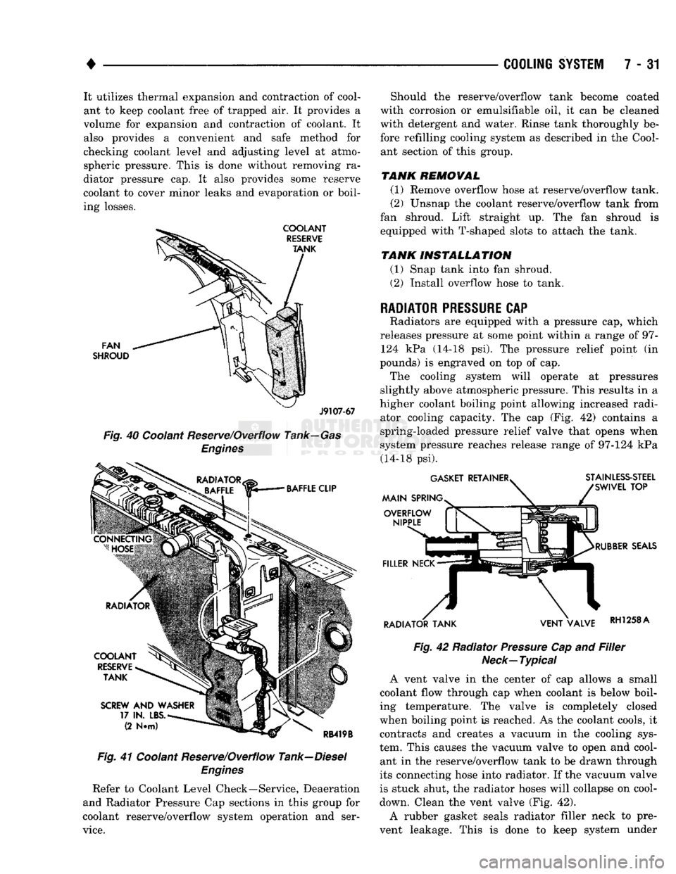
Fig.
40 Coolant Reserve/Overflow Tank—Gas
Engines
Fig.
41 Coolant Reserve/Overflow Tank—Diesel
Engines
Refer to Coolant Level Check—Service, Deaeration
and Radiator Pressure Cap sections in this group for
coolant reserve/overflow system operation and ser
vice.
Should the reserve/overflow tank become coated
with corrosion or emulsifiable oil, it can be cleaned
with detergent and water. Rinse tank thoroughly be
fore refilling cooling system as described in the Cool ant section of this group.
TANK REMOVAL
(1) Remove overflow hose at reserve/overflow tank.
(2) Unsnap the coolant reserve/overflow tank from
fan shroud. Lift straight up. The fan shroud is
equipped with T-shaped slots to attach the tank.
TANK INSTALLATION
(1) Snap tank into fan shroud.
(2) Install overflow hose to tank.
RADIATOR
PRESSURE
CAP
Radiators are equipped with a pressure cap, which
releases pressure at some point within a range of 97- 124 kPa (14-18 psi). The pressure relief point (in
pounds) is engraved on top of cap. The cooling system will operate at pressures
slightly above atmospheric pressure. This results in a
higher coolant boiling point allowing increased radi ator cooling capacity. The cap (Fig. 42) contains a
spring-loaded pressure relief valve that opens when
system pressure reaches release range of 97-124 kPa (14-18 psi).
Fig.
42 Radiator
Pressure
Cap and
Filler
Neck—Typical
A vent valve in the center of cap allows a small
coolant flow through cap when coolant is below boil
ing temperature. The valve is completely closed
when boiling point is reached. As the coolant cools, it contracts and creates a vacuum in the cooling sys
tem. This causes the vacuum valve to open and cool ant in the reserve/overflow tank to be drawn through
its connecting hose into radiator. If the vacuum valve
is stuck shut, the radiator hoses will collapse on cool-
down. Clean the vent valve (Fig. 42).
A rubber gasket seals radiator filler neck to pre
vent leakage. This is done to keep system under
Page 304 of 1502
•
COOLING
SYSTEM
7 - 33 The radiator supplies sufficient heat transfer to
cool the engine and automatic transmission (if equipped).
RADIATOR COOLANT FLOW CHECK
Use the following procedure to determine if coolant
is flowing through the cooling system.
(1) Idle engine until operating temperature is
reached. If the upper radiator hose is warm to the
touch, the thermostat is opening and coolant is flow ing to the radiator.
WARNING:
HOT,
PRESSURIZED COOLANT
CAN
CAUSE
INJURY
BY
SCALDING. USING
A
RAG
TO
COVER
THE
RADIATOR
PRESSURE
CAP,
OPEN RADIATOR
CAP
SLOWLY
TO THE
FIRST STOP.
THIS
WILL
ALLOW
ANY
BUILT-UP
PRESSURE
TO
VENT
TO
THE
RESERVE/OVERFLOW TANK. AFTER
PRESSURE
BUILD-UP
HAS
BEEN RELEASED,
RE
MOVE
CAP
FROM FILLER NECK.
(2) Drain a small amount of coolant from the radi
ator until the ends of the radiator tubes are visible
through the filler neck. Idle the engine at normal op
erating temperature. If coolant is flowing past the
exposed tubes, the coolant is circulating.
RADIATOR REMOVAL-EXCEPT DIESEL
(1) Disconnect negative battery cable from battery.
WARNING;
DO NOT
REMOVE
THE
CYLINDER BLOCK DRAIN PLUGS
OR
LOOSEN
THE
RADIATOR
DRAINCOCK
WITH
THE
SYSTEM
HOT AND
UNDER
PRESSURE.
SERIOUS BURNS FROM COOLANT
CAN OCCUR.
(2) Drain the cooling system. Refer to Draining
Cooling System.
(3) Disconnect throttle cable from clip at radiator
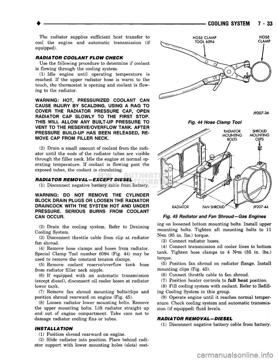
fan shroud. (4) Remove hose clamps and hoses from radiator.
Special Clamp Tool number 6094 (Fig. 44) may be
used to remove the constant tension clamps.
(5) Remove coolant reserve/overflow tank hose
from radiator filler neck nipple.
(6) If equipped with an automatic transmission
(except diesel), disconnect oil cooler hoses at radiator
lower tank.
(7) Remove fan shroud mounting bolts/clips and
position shroud rearward on engine (Fig. 45). (8) Loosen radiator lower mounting bolts. Remove
the upper mounting bolts. Lift radiator straight up and out of engine compartment. Take care not to
damage radiator cooling fins or tubes.
INSTALLATION
(1) Position shroud rearward on engine.
(2) Slide radiator into position. Place behind radi
ator support with lower mounting holes (slots) rest-
HOSE
CLAMP
TOOL
6094
HOSE
CLAMP
J9207-36
Fig.
44
Hose
Clamp
Tool
RADIATOR SHROUD
MOUNTING MOUNTING
BOLTS
CUPS
RADIATOR
V1
FAN SHROUD^
J9207-44
Fig.
45 Radiator and Fan
Shroud—Gas Engines
ing on loosened bottom mounting bolts. Install upper
mounting bolts. Tighten all mounting bolts to 11
N*m (95 in. lbs.) torque.
(3) Connect radiator hoses.
(4) Connect transmission oil cooler lines to bottom
tank. Tighten hose clamps to 4 N#m (35 in. lbs.)
torque.
(5) Position fan shroud on radiator flange. Install
mounting clips (Fig. 45).
(6) Connect throttle cable to fan shroud.
(7) Position heater controls to full heat position.
(8) Fill cooling system with coolant. Refer to Refill
ing Cooling System in this group.
(9) Operate engine until it reaches normal temper
ature. Check cooling system and automatic transmis
sion (if equipped) fluid levels.
RADIATOR REMOVAL-DIESEL
(1) Disconnect negative battery cable from battery.
Page 319 of 1502
7
- 48
COOLING
SYSTEM
•
ENGINE BLOCK HEATERS
GENERAL
INFORMATION
DESCRIPTION AND OPERATION An optional engine block heater
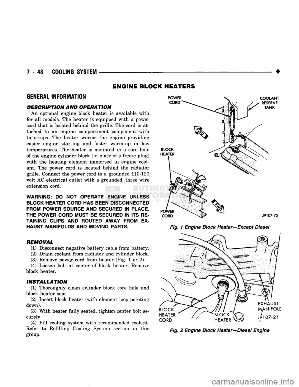
is
available with
for
all
models. The heater
is
equipped with
a
power
cord that
is
located behind the grille. The cord
is at
tached
to an
engine compartment component with
tie-straps.
The
heater warms
the
engine providing easier engine starting
and
faster warm-up
in low
temperatures. The heater
is
mounted
in a
core hole of the engine cylinder block (in place of
a
freeze plug)
with
the
heating element immersed
in
engine cool ant.
The
power cord
is
located behind
the
radiator
grille. Connect the power cord
to a
grounded 110-120
volt AC electrical outlet with
a
grounded, three wire
extension cord.
WARNING:
DO NOT
OPERATE ENGINE
UNLESS
BLOCK
HEATER
CORD
HAS
BEEN
DISCONNECTED
FROM POWER
SOURCE
AND
SECURED
IN
PLACE.
THE POWER
CORD
MUST BE
SECURED
IN ITS RE
TAINING
CLIPS
AND ROUTED AWAY FROM
EX
HAUST MANIFOLDS AND MOVING
PARTS.
REMOVAL
(1) Disconnect negative battery cable from battery.
(2) Drain coolant from radiator and cylinder block.
(3) Remove pow^r cord from heater (Fig.
1 or 2).
(4)
Loosen bolt
at
center
of
block heater. Remove
block heater.
INSTALLATION (1) Thoroughly clean cylinder block core hole
and
block heater seat. (2) Insert block heater (with element loop pointing
down).
(3) With heater fully seated, tighten center bolt se
curely.
(4)
Fill cooling system with recommended coolant.
Refer
to
Refilling Cooling System section
in
this
group.
Fig.
1
Engine
Block
Heater—Except
Diesel
Fig.
2
Engine
Block
Heater—Diesel
Engine
Page 352 of 1502
•
IGNITION
SYSTEMS
8D
- 1
CONTENTS
page page
COMPONENT IDENTIFICATION/SYSTEM DIAGNOSTICS/SERVICE PROCEDURES
7
OPERATION
1
IGNITION SWITCH
25
COMPONENT REMOVAL/INSTALLATION
..... 18
SPECIFICATIONS
28
COMPONENT
IDENTIFICATION/SYSTEM OPERATION
INDEX
page
Automatic
Shut Down (ASD) Relay
1
Camshaft Position Sensor
2
Crankshaft Position Sensor
2
Distributors
3
Engine Coolant
Temperature
Sensor
...........
4
General
Information
1
page
Ignition
Coil
3
Intake
Manifold Charge
Air
Temperature
Sensor
. . 4
Manifold Absolute Pressure (MAP) Sensor
4
Powertrain
Control
Module (PCM)
. 5
Throttle
Position Sensor
5
GENERAL
INFORMATION
Throughout this group, references
are
made
to
par
ticular vehicle models
by
alphabetical designation
or
by
the
particular vehicle nameplate.
A
chart showing a breakdown
of
alphabetical designations
is
included
in
the
Introduction group
at the
beginning
of
this
manual. 5.9L
gas
powered engines will
be
referred
to as ei
ther: LDC (Light Duty Cycle),
or
HDC (Heavy Duty Cycle). This section
of the
group, Component Identifica
tion/System Operation, will discuss ignition system operation
and
will identify ignition system compo
nents.
For diagnostic procedures
and
adjustments, refer
to
the Diagnostics/Service Procedures section
of
this
group.
For removal
and
installation
of
ignition system
components, refer
to the
Component Removal/Instal
lation section
of
this group. For other useful information, refer
to
On-Board
Di
agnostics
in the
General Diagnosis sections
of
Group
14,
Fuel System
in
this manual. For operation
of the DRB II
Diagnostic Scan Tool,
refer
to the
appropriate Powertrain Diagnostic Proce
dures service manual.
An Ignition specifications section
is
included
at the
end
of
this group.
A
general Maintenance Schedule (mileage intervals)
for
ignition related items
can be
found
in
Group
0,
Lubrication and Maintenance. This
schedule
can
also
be
found
in the
Owners Manual.
IGNITION
SYSTEMS
The ignition systems used
on all
engines
are
basi
cally identical. Similarities
and
differences between
the systems will
be
discussed.
A sequential multi-port fuel injection system
is
used
on all gas
powered engines.
The ignition system
is
controlled
by the
powertrain
control module (PCM)
on all
engines.
The
PCM
was
formerly referred
to as the
SBEC
or
engine control ler.
The ignition system consists
of:
• Spark Plugs
• Ignition Coil
• Secondary Ignition Cables
• Ignition distributor. Contains rotor
and
camshaft
position sensor • Powertrain Control Module (PCM)
• Crankshaft Position Sensor
AUTOMATIC SHUT DOWN (ASD) RELAY
The automatic shut down (ASD) relay
is
located
in
the engine compartment (Fig.
1). As one of its
func
tions,
the ASD
relay will supply battery voltage
to
the ignition coil.
The
ground circuit
for the
ASD
re
lay
is
controlled
by the
powertrain control module (PCM).
The PCM
regulates
ASD
relay operation
by
switching
the
ground circuit on-and-off.
IGNITION
SYSTEMS
Page 355 of 1502
8D
- 4
IGNITION
SYSTEMS
•
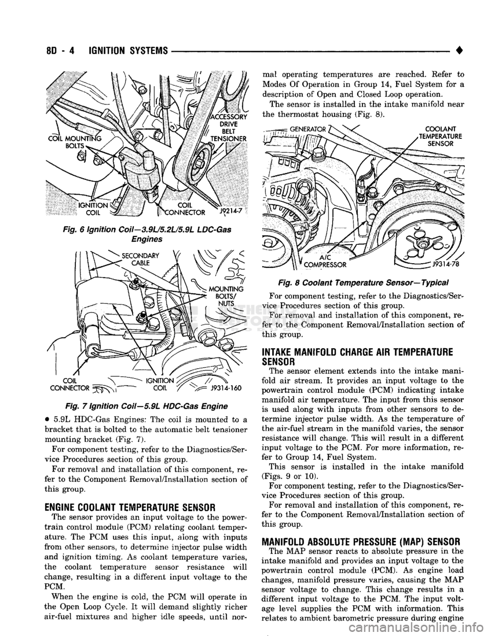
Fig. 6 ignition Coil—3.9L/5.2L/5.9L
LDC-Gas
Engines Fig. 7 Ignition Coil—5.9L
HDC-Gas
Engine
• 5.9L HDC-Gas Engines: The coil is mounted to a
bracket that is bolted to the automatic belt tensioner mounting bracket (Fig. 7).
For component testing, refer to the Diagnostics/Ser
vice Procedures section of this group.
For removal and installation of this component, re
fer to the Component Removal/Installation section of
this group.
ENGINE COOLANT TEMPERATURE
SENSOR
The sensor provides an input voltage to the power-
train control module (PCM) relating coolant temper ature. The PCM uses this input, along with inputs
from other sensors, to determine injector pulse width and ignition timing. As coolant temperature varies,
the coolant temperature sensor resistance will
change, resulting in a different input voltage to the
PCM. When the engine is cold, the PCM will operate in
the Open Loop Cycle. It will demand slightly richer air-fuel mixtures and higher idle speeds, until nor mal operating temperatures are reached. Refer to
Modes Of Operation in Group 14, Fuel System for a
description of Open and Closed Loop operation.
The sensor is installed in the intake manifold near
the thermostat housing (Fig. 8).
Fig. 8 Coolant Temperature Sensor—Typical
For component testing, refer to the Diagnostics/Ser
vice Procedures section of this group. For removal and installation of this component, re
fer to the Component Removal/Installation section of
this group.
INTAKE MANIFOLD CHARGE
AIR
TEMPERATURE
SENSOR
The sensor element extends into the intake mani
fold air stream. It provides an input voltage to the
powertrain control module (PCM) indicating intake
manifold air temperature. The input from this sensor is used along with inputs from other sensors to de
termine injector pulse width. As the temperature of
the air-fuel stream in the manifold varies, the sensor
resistance will change. This will result in a different input voltage to the PCM. For more information, re
fer to Group 14, Fuel System. This sensor is installed in the intake manifold
(Figs.
9 or 10). For component testing, refer to the Diagnostics/Ser
vice Procedures section of this group. For removal and installation of this component, re
fer to the Component Removal/Installation section of
this group.
MANIFOLD ABSOLUTE
PRESSURE
(MAP)
SENSOR
The MAP sensor reacts to absolute pressure in the
intake manifold and provides an input voltage to the
powertrain control module (PCM). As engine load changes, manifold pressure varies, causing the MAP
sensor voltage to change. This change results in a
different input voltage to the PCM. The input volt age level supplies the PCM with information. This
relates to ambient barometric pressure during engine
Page 358 of 1502
•
IGNITION
SYSTEMS
80 - 7
DIAGNOSTICS/SERW1CE
PROCEDURES
INDEX
page
Automatic Shut Down (ASD) Relay
7
Camshaft Position
Sensor
Test
...............
7
Crankshaft Position
Sensor
Test
8
Distributor
Cap
8
Distributor
Rotor
8
Engine
Coolant Temperature
Sensor
Test
10
General
Information
7
Ignition
Coil
8
Ignition
Secondary
Circuit
Diagnosis
10
GENERAL
INFORMATION
This section
of the
group, Diagnostics/Service Pro
cedures, will discuss basic ignition system diagnos
tics
and
service adjustments. For system operation
and
component identification,
refer
to the
Component Identification/System Opera
tion section
of
this group. For removal
or
installation
of
ignition system com
ponents, refer
to the
Component Removal/Installa
tion section
of
this group. For other useful information, refer
to
On-Board
Di
agnostics
in the
General Diagnosis sections
of
Group
14,
Fuel System
in
this manual. For operation
of the DRB II
Diagnostic Scan Tool,
refer
to the
appropriate Powertrain Diagnostic Proce
dures service manual.
AUTOMATIC SHUT DOWN
(ASD)
RELAY
Refer
to
Relays—Operation/Testing
in the
Group
14,
Fuel System section
of
this service manual.
CAMSHAFT POSITION SENSOR TEST
The camshaft position sensor
is
located
in the
dis
tributor
on all
engines. To perform
a
complete test
of
this sensor
and its
circuitry, refer
to the DRB II
diagnostic scan tool.
Also refer
to the
appropriate Powertrain Diagnostics
Procedures manual.
To
test
the
sensor only, refer
to
the following: For this test,
an
analog (non-digital) voltmeter
is needed.
Do not
remove
the
distributor connector from
the
distributor. Using small paper clips, insert
them into
the
backside
of the
distributor wire har ness connector
to
make contact with
the
terminals.
Be sure that
the
connector
is not
damaged when
in
serting
the
paper clips. Attach voltmeter leads
to
these paper clips. (1) Connect
the
positive (
+
)
voltmeter lead into
the sensor output wire. This
is at
done
the
distribu tor wire harness connector.
For
wire identification,
refer
to
Group
8W,
Wiring Diagrams.
page
Ignition
Timing
12
Intake Manifold Charge
Air
Temperature
Sensor
Test
12
Manifold Absolute Pressure (MAP)
Sensor
Test
. 12
Oxygen
Sensor
Tests
17
Powertrain Control Module (PCM)
............
14
Spark
Plug Secondary Cables
16
Spark
Plugs
............................
14
Throttle
Position
Sensor
Test
17
(2) Connect
the
negative
(-)
voltmeter lead into
the
ground wire.
For
wire identification, refer
to
Group
8W, Wiring Diagrams.
(3)
Set the
voltmeter
to the 15
Volt
DC
scale. (4) Remove distributor
cap
from distributor
(two
screws). Rotate (crank)
the
engine until
the
distribu
tor rotor
is
pointed towards
the
rear
of
vehicle.
The
movable pulse ring should
now be
within
the
sensor
pickup.
(5) Turn ignition
key to ON
position. Voltmeter
should read approximately
5.0
volts.
(6)
If
voltage
is not
present, check
the
voltmeter
leads
for a
good connection.
(7)
If
voltage
is
still
not
present, check
for
voltage
at
the
supply wire.
For
wire identification, refer
to
Group
8W,
Wiring Diagrams.
(8)
If
voltage
is not
present
at
supply wire, check
for voltage
at
pin-7
of
powertrain control module (PCM) 60-way connector. Leave
the PCM
connector
connected
for
this test. (9)
If
voltage
is
still
not
present, perform vehicle
test using
the DRB II
diagnostic scan tool. (10)
If
voltage
is
present
at
pin-7,
but not at the
supply wire: (a) Check continuity between
the
supply wire.
This
is
checked between
the
distributor connector and pin-7
at the PCM. If
continuity
is not
present,
repair
the
harness
as
necessary. (b) Check
for
continuity between
the
camshaft
position sensor output wire
and
pin-44
at the PCM.
If continuity
is not
present, repair
the
harness
as
necessary. (c) Check
for
continuity between
the
ground cir
cuit wire
at the
distributor connector
and
ground.
If continuity
is not
present, repair
the
harness
as
necessary. (11) While observing
the
voltmeter, crank
the en
gine with ignition switch.
The
voltmeter needle should fluctuate between
0 and 5
volts while
the en
gine
is
cranking. This verifies that
the
camshaft
po
sition sensor
in the
distributor
is
operating properly
and
a
sync pulse signal
is
being generated.