1993 DODGE TRUCK recommended oil
[x] Cancel search: recommended oilPage 37 of 1502
0-18
LUBRICATION
AND
MAINTENANCE
• MAINTENANCE SCHEDULE
A crankcase ventilation system must be clean to
provide good operation and durability. Periodic main
tenance is necessary. Replace the PCV valve. Re
move residual combustion deposits from the hoses and throttle body/intake manifold passages.
The PCV valve should be replaced and the system
should be serviced at the interval specified in main
tenance schedule. If a vehicle is routinely used for short trips, the crankcase ventilation system could
possibly require more maintenance.
CRANKCASE AIR INLET FILTER
MAINTENANCE SCHEDULE Replace or clean, the air inlet filter at the interval
specified in maintenance schedule.
More frequent PCV system maintenance could be
required for:
• Vehicles routinely used for short trips
• Vehicles routinely involved in stop and go traffic
operation
• Vehicles routinely involved in extended periods of
engine idle
MAINTENANCE Clean and lubricate the crankcase air inlet filter
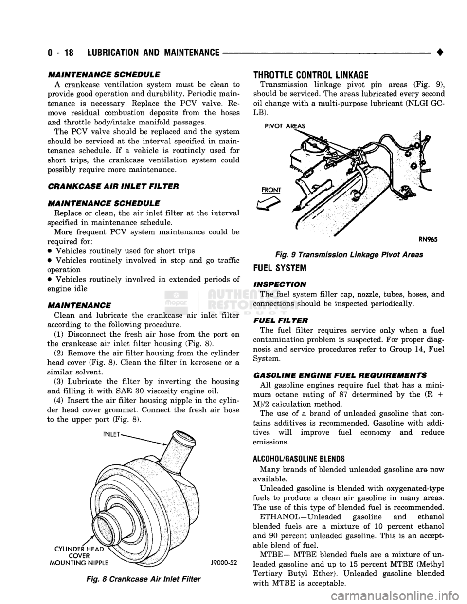
according to the following procedure. (1) Disconnect the fresh air hose from the port on
the crankcase air inlet filter housing (Fig. 8).
(2) Remove the air filter housing from the cylinder
head cover (Fig. 8). Clean the filter in kerosene or a similar solvent.
(3) Lubricate the filter by inverting the housing
and filling it with SAE 30 viscosity engine oil.
(4) Insert the air filter housing nipple in the cylin
der head cover grommet. Connect the fresh air hose
to the upper port (Fig. 8).
J9000-52
Fig.
8
Crankcase
Air Inlet
Filter
THROTTLE CONTROL LINKAGE
Transmission linkage pivot pin areas (Fig. 9),
should be serviced. The areas lubricated every second
oil change with a multi-purpose lubricant (NLGI GC-
LB).
PIVOT
AREAS
Fig.
9
Transmission
Linkage
Pivot Areas
FUEL
SYSTEM
INSPECTION The fuel system filler cap, nozzle, tubes, hoses, and
connections should be inspected periodically.
FUEL FILTER The fuel filter requires service only when a fuel
contamination problem is suspected. For proper diag
nosis and service procedures refer to Group 14, Fuel
System.
GASOLINE ENGINE FUEL REQUIREMENTS All gasoline engines require fuel that has a mini
mum octane rating of 87 determined by the (R +
M)/2 calculation method.
The use of a brand of unleaded gasoline that con
tains additives is recommended. Gasoline with addi
tives will improve fuel economy and reduce emissions.
ALCOHOL/GASOLINE
BLENDS
Many brands of blended unleaded gasoline am now
available. Unleaded gasoline is blended with oxygenated-type
fuels to produce a clean air gasoline in many areas.
The use of this type of blended fuel is recommended.
ETH ANOL—Unleaded gasoline and ethanol
blended fuels are a mixture of 10 percent ethanol and 90 percent unleaded gasoline. This is an accept
able blend of fuel.
MTBE— MTBE blended fuels are a mixture of un
leaded gasoline and up to 15 percent MTBE (Methyl
Tertiary Butyl Ether). Unleaded gasoline blended
with MTBE is acceptable.
Page 40 of 1502
•
LUBRICATION
AND
MAINTENANCE
0 - 21 ROUTINE INSPECTION
It is recommended that the drive belt(s) be rou
tinely inspected for cracks, fraying and excessive
wear. Replace as necessary.
EXHAUST SYSTEM
An exhaust system must be properly aligned to
prevent stress, leakage, and vehicle body contact.
MAINTENANCE SCHEDULE Inspect the exhaust system at the interval specified
in maintenance schedule.
INSPECTION Inspect for cracked or loose joints, corrosion dam
age,
and worn or broken hangers. Replace all compo
nents that are damaged. Do not attempt repair. Also,
inspect for the following conditions and correct as
necessary:
• Exhaust system leaks, misalignment • Contact with body panels or the frame
• Catalytic converter bulging or excessive heat dam
age
CAUTION:
A
catalytic converter
will
become
con
taminated
if
leaded gasoline
is
burned
in the en
gine.
If
this
occurs,
the
complete converter must
be
replaced.
AIR-CONDITIONER COMPRESSOR LUBRICANT
AND
REFRIGERANT
The lubricant level in the compressor should be
checked if there are indications that oil was lost.
Loss of lubricating oil usually accompanies a loss of
refrigerant. The presence of bubbles in sight glass in dicates that loss of refrigerant has occurred. For additional information involving the A/C sys
tem, refer to Group 24—Heater And Air Condition ing.
Page 42 of 1502
•
LUBRICATION
AND
MAINTENANCE
0 - 23 GEAR SHIFTER BOOTS
Inspect the shifter boots periodically for stone and
heat damage. Replace, if necessary.
SEVERE DRIVING CONDITIONS The interval between the transmission drain and
refill maintenance should be decreased to:
• NV4500 manual transmission—every 29 000 km (18,000 miles)
• Automatic transmission—every 19 000 km (12,000
miles)
A severe driving condition includes:
• Extended operation with heavy cargo loads
• Driving in deep mud or snow
• Off-road operation (4WD)
• Trailer towing
• Operation as a commercial vehicle
• Snow plowing
MANUAL TRANSMISSIONS
INSPECTION/LUBE
OIL
LEVEL
The transmission should be checked for leaks when
other service is necessary under the vehicle. To check
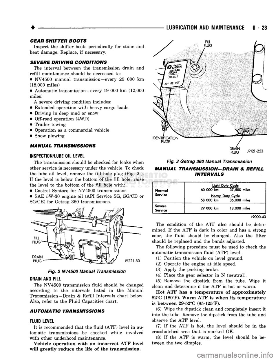
the lube oil level, remove the fill hole plug (Fig. 2 ). If the level is below the bottom of the fill hole, raise
the level to the bottom of the fill hole with:
• Castrol Syntorq for NV4500 transmissions
• SAE 5W-30 engine oil (API Service SG, SG/CD or
SG/CE) for Getrag 360 transmissions.
Fig.
2 NV4500 Manual
Transmission
DRAIN
AND
FILL
The NV4500 transmission fluid should be changed
according to the intervals listed in the Manual
Transmission—Drain & Refill Intervals chart below.
Also,
refer to the Fluid Capacities chart.
AUTOMATIC TRANSMISSIONS
FLUID
LEWEL
It is recommended that the fluid (ATF) level in au
tomatic transmissions be checked while involved
with other underhood maintenance.
Vehicle operation with an incorrect ATF level
will greatly reduce the life of the transmission.
Fig.
3 Getrag 360 Manual
Transmission
MANUAL TRANSMISSION-DRAIN & REFILL INTERVALS
Normal
Service
Light
Duty
Cycle
60 000
km
37,500
miles
Heavy
Duty
Cycle
58 000
km
36,000
miles
Severe
Service
29 000
km
18,000
miles
J9000-43
The condition of the ATF also should be deter
mined. If the ATF is dark in color and has a strong odor, the fluid should be changed. Also the filter should be replaced and the bands adjusted.
The following procedure must be used to check the
automatic transmission fluid (ATF) level.
(1) Position the vehicle on level ground.
(2) Operate the engine at idle speed.
(3) Apply the parking brake.
(4) Place the gear selector in N (neutral).
(5) Remove the dipstick from the tube. Wipe it
clean and determine if the ATF is hot or warm.
Hot ATF has a temperature of approximately
82°C (180°F). Warm ATF is when its temperature
is between 29-52°C (85-125°F). (6) Wipe the dipstick clean and completely insert it
into the tube. Remove the dipstick from the tube and
observe the ATF level.
(7) If the ATF is hot, the level should be in the
crosshatched area that is marked OK.
(8) If the ATF is warm, the level should be be
tween the two dimples.
Page 43 of 1502
0
- 24
LUBRICATION
AND
MAINTENANCE
•
CAUTION:
Do not
overfill
the
transmission.
(9) Adjust
the
level
of the ATF
accordingly.
It
is
important
to use the
correct fluid
in an
automatic transmission. MOPAR®ATF PLUS
(ATF Type
7176)
should
be
used. Dexron®
II
ATF
can be
used
if the
recommended fluid
is not
available,
(10) Insert
the
dipstick into
the
tube.
DRAIN, FILTER CHANGE, BAND ADJUSTMENT AND REFILL
The chart below lists
the
intervals
at
which
the
transmission should
be
serviced. Also, refer
to the
Fluid Capacities chart
for
fill capacity.
AUTOMATIC TRANSMISSION SERVICE
IN-
TERVALS
Normal
Usage
Light
Duty
Cycle
60 000
km
37,500
miles
Heavy
Duty
Cycle
38
000 km 24,000
miles
Severe
Usage
19 000 km 12,000
miles
J9100-19
It
is
very important
to use the
correct fluid
in
an automatic transmission. MOPAR®ATF PLUS
(ATF Type
7176)
should
be
used.
An
equivalent
Dexron®
II ATF
could
be
used only
if the
recom
mended fluid
is not
available.
The torque converter does
not
have
a
drain plug.
No attempt should
be
made
to
drain
the
converter.
Refer
to
Group
21
—Transmissions
for
transmission
drain
and
refill procedures.
TRANSFER
CASE
(4WD
VEHICLES)
INSPECTION The NP205
and
NP241 transfer cases fluid level
should
be
checked whenever maintenance
is
neces
sary under
the
vehicle.
FLUID
LEVEL
The vehicle must
be
level when
the
fluid level
is checked.
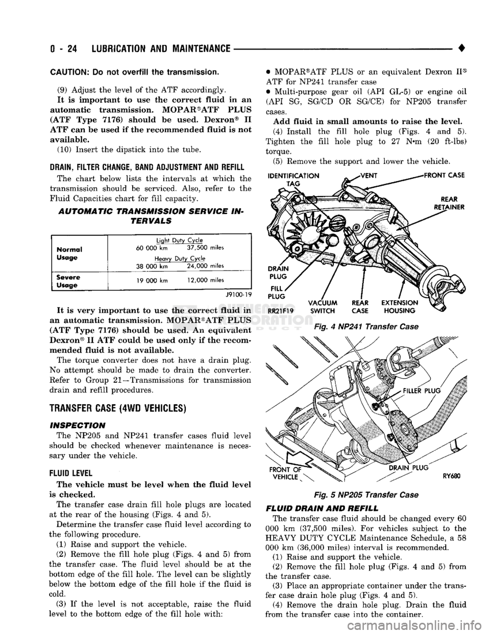
The transfer case drain fill hole plugs
are
located
at
the
rear
of the
housing (Figs.
4 and 5).
Determine
the
transfer case fluid level according
to
the following procedure.
(1) Raise
and
support
the
vehicle.
(2) Remove
the
fill hole plug (Figs.
4 and 5)
from
the transfer case.
The
fluid level should
be at the
bottom edge
of the
fill hole.
The
level
can be
slightly
below
the
bottom edge
of the
fill hole
if the
fluid
is
cold.
(3)
If the
level
is not
acceptable, raise
the
fluid
level
to the
bottom edge
of the
fill hole with: • MOPAR®ATF PLUS
or an
equivalent Dexron
II®
ATF
for
NP241 transfer case
• Multi-purpose gear
oil (API GL-5) or
engine
oil
(API
SG,
SG/CD
OR
SG/CE)
for
NP205 transfer
cases.
Add fluid
in
small amounts
to
raise
the
level. (4) Install
the
fill hole plug (Figs.
4 and 5).
Tighten
the
fill hole plug
to 27 N-m (20
ft-lbs) torque.
(5) Remove
the
support
and
lower
the
vehicle.
Fig.
4
HP241 Transfer
Case
Fig.
5
NP205 Transfer
Case
FLUID DRAIN
AND
REFILL The transfer case fluid should
be
changed every
60
000
km
(37,500 miles).
For
vehicles subject
to the
HEAVY DUTY CYCLE Maintenance Schedule,
a 58
000
km
(36,000 miles) interval
is
recommended.
(1) Raise
and
support
the
vehicle.
(2) Remove
the
fill hole plug (Figs.
4 and 5)
from
the transfer case. (3) Place
an
appropriate container under
the
trans
fer case drain hole plug (Figs.
4 and 5).
(4) Remove
the
drain hole plug. Drain
the
fluid
from
the
transfer case into
the
container.
Page 47 of 1502
0
- 28
LUBRICATION
AND
MAINTENANCE
•
CHASSIS AND BODY
page
Body
Component Mechanisms
32
Front
Suspension
Ball
Joints
28
Front
Wheel Bearings
29
Headlamps
32
Lower
and
Upper Suspension
Arm
Bushings
.... 30
Manual
Steering Gear
28
STEERING
LINKAGE
INSPECTION When
a
vehicle
is
raised
for
maintenance under
the vehicle,
all
steering components should
be
checked.
LUBRICATION SCHEDULE The steering linkage
is
lubricated with
a
chassis
lubricant. However,
it is
recommended that
the
link
age
be
inspected
and
lubricated after each:
•
24 000 km
(15,000 miles) interval
or
every
6
months,
for 2WD
vehicles subject
to the
LIGHT
DUTY CYCLE Maintenance Schedule
•
9 600 km
(6,000 miles) interval
or
every
6
months,
for
2WD
vehicles subject
to the
HEAVY DUTY
CY
CLE Maintenance Schedule
•
12 000 km
(7,500 miles) interval
or
every
6
months,
for 4WD
vehicles subject
to the
LIGHT DUTY CYCLE Maintenance Schedule
•
9 600 km
(6,000 miles) interval
or
every
6
months,
for
4WD
vehicles subject
to the
HEAVY DUTY
CY
CLE Maintenance Schedule.
LUBRICATION (1) Inspect
the
steering linkage
for
looseness
and
excessive wear. (2) Replace,
all
ruptured seals
and
damaged steer
ing linkage components. Damaged seals should
be re
placed
to
prevent leakage
and
contamination
of the
lubricant.
CAUTION:
Use
care
to
prevent lubricant from
con
tacting
the
brake rotors.
(3) Lubricate
the
steering linkage:
• Clean
the
Zerk type lubrication fittings
on the tie-
rod
and
center link ball-stud ends
• Lubricate
the
ball studs with MOPAR®Multi-Mile- age Lubricant
• Wipe
the
excess lubricant from
the
exterior sur
faces
of the
ball joints
page
Power
Brake System
30
Power
Steering System
. . 29
Rear
Wheel Bearings
30
Speedometer Cable
33
Steering Linkage
28
Tires
32
FRONT
SUSPENSION
BALL JOINTS
INSPECTION When
a
vehicle
is
raised
for
lubrication/general
maintenance,
the
ball joints should
be
inspected.
LUBRICATION SCHEDULE The front suspension ball joints
are
lubricated dur
ing manufacture with
a
long-life chassis lubricant.
However,
it is
recommended that
the
ball joints
be
inspected
and the
studs lubricated:
•
At
each
36 000 km
(22,500 miles) interval
or
every
2 years,
for
vehicles subject
to the
LIGHT DUTY
CY
CLE Maintenance Schedule
•
At
each
9 600 km
(6,000 miles) interval
or
every
2
years,
for
vehicles subject
to the
HEAVY DUTY
CY
CLE Maintenance Schedule.
4WD vehicles that
are
frequently driven
off-
road should
be
lubricated
at
every engine
oil
change.
LUBRICATION (1) Inspect
the
front suspension. Examine
the
ball
studs
for
looseness
and
excessive wear. (2) Replace
all
torn ball-stud seals
and
damaged
ball joints. Damaged seals should
be
replaced
to
pre vent leakage
and
contamination.
CAUTION:
Use
care
to
prevent lubricant from
con
tacting
the
brake rotors.
(3) Lubricate
the
ball studs:
• Clean
the
Zerk type lubrication fittings
on the
ball-stud ends
• Lubricate
the
ball studs with MOPAR®Multi-Mile-age Lubricant
• Wipe
the
excess lubricant from
the
exterior sur
faces
of the
ball joints
MANUAL
STEERING
GEAR
LUBRICATION Manual steering gears
are
permanently lubricated
during manufacture. Periodic lubrication
is not
nec
essary.
Page 51 of 1502
0
- 32
LUBRICATION
AND
MAINTENANCE
•
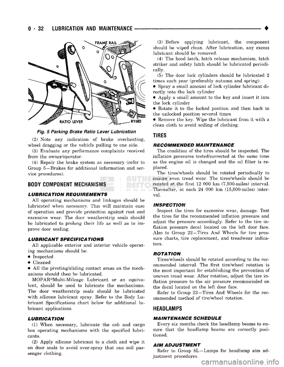
Fig.
5 Parking Brake Ratio Lever Lubrication (2) Note any indication of brake overheating,
wheel dragging or the vehicle pulling to one side.
(3) Evaluate any performance complaints received
from the owner/operator. (4) Repair the brake system as necessary (refer to
Group 5—Brakes for additional information and ser
vice procedures).
BODY
COMPONENT
MECHANISMS
LUBRICATION REQUIREMENTS
All operating mechanisms and linkages should be
lubricated when necessary. This will maintain ease of operation and provide protection against rust and
excessive wear. The door weatherstrip seals should
be lubricated to prolong their life as well as to im prove door sealing.
LUBRICANT SPECIFICATIONS
All applicable exterior and interior vehicle operat
ing mechanisms should be:
• Inspected • Cleaned
• All the pivoting/sliding contact areas on the mech anisms should then be lubricated.
MOPAR®Multi-Mileage Lubricant or an equiva
lent, should be used to lubricate the mechanisms.
The door weatherstrip seals should be lubricated
with silicone lubricant spray. Refer to the Body Lu
bricant Specifications chart below for additional lu
bricant applications.
LUBRICATION
(1) When necessary, lubricate the cab and cargo
box operating mechanisms with the specified lubri
cants.
(2) Apply silicone lubricant to a cloth and wipe it
on door seals to avoid over-spray that can soil pas
senger clothing. (3) Before applying lubricant, the component
should be wiped clean. After lubrication, any excess
lubricant should be removed.
(4) The hood latch, latch release mechanism, latch
striker and safety latch should be lubricated periodi
cally.
(5) The door lock cylinders should be lubricated 2
times each year (preferably autumn and spring): • Spray a small amount of lock cylinder lubricant di
rectly into the lock cylinder
• Apply a small amount to the key and insert it into
the lock cylinder • Rotate it to the locked position and then back to
the unlocked position several times
• Remove the key. Wipe the lubricant from it with a
clean cloth to avoid soiling of clothing.
TIRES
RECOMMENDED MAINTENANCE
The condition of the tires should be inspected. The
inflation pressures tested/corrected at the same time as the engine oil is changed and the oil filter is re
placed.
The tires/wheels should be rotated periodically to
ensure even tread wear. The tires/wheels should be
rotated at the first 12 000 km (7,500-miles) interval.
Thereafter, at each 24 000 km (15,000-miles) inter
val.
INSPECTION
Inspect the tires for excessive wear, damage. Test
the tires for the recommended inflation pressure and adjust the pressure accordingly. Refer to the tire in
flation pressure decal located on the left door face. Also to Group 22—Tires And Wheels for tire pressure charts, tire replacement, and treadwear indica
tors.
ROTATION
Tires/wheels should be rotated according to the rec
ommended interval. The first tire/wheel rotation is
the most important for establishing the prevention of uneven tread wear. After rotation, adjust the tire in
flation pressure to the air pressure recommended on
the decal located on the left door face.
Refer to Group 22—Tires And Wheels for the rec
ommended method of tire/wheel rotation.
HEADLAMPS
MAINTENANCE SCHEDULE
Every six months check the headlamp beams to en
sure that the headlamp beams are correctly posi
tioned.
AIM
ADJUSTMENT
Refer to Group 8L—Lamps for headlamp aim ad
justment procedures.
Page 104 of 1502
FRONT
SUSPENSION
AND
AXLE
2 - 51
LUBRICANT
Multi-purpose API GL 5 quality hypoid gear lubri
cant should be used for Model 60 axles. MOPAR Hy
poid Gear Lubricant conforms to these specifications and is recommended.
CAUTION:
If a front axle is
submerged
in
water,
the
axle lubricant
must
be replaced immediately.
DRAIN AND REFILL
(1) Drive the vehicle until the gear lubricant
reaches normal operating temperature. (2) Raise and support the vehicle.
(3) Remove the lubricant fill hole plug from the
differential housing cover. (4) Remove the differential housing cover. Allow
the original lubricant to completely drain from the
housing and axle shaft tubes. (5) With standard differential, clean the differen
tial and the housing cavity with a flushing oil (or light engine oil). This will remove the residual lubricant and foreign matter. Do not use water, steam,
kerosene or gasoline for flushing. (6) Scrape the residual gasket from the housing
and cover mating surfaces. Clean the mating sur
faces with mineral spirits. Install a new cover gas
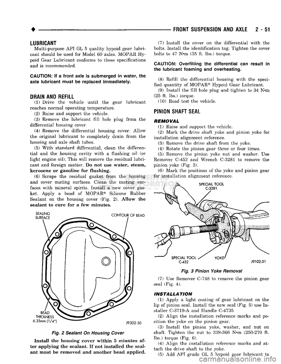
ket. Apply a bead of MOPAR® Silicone Rubber Sealant on the housing cover (Fig. 2). Allow the
sealant to cure for a few minutes.
SEALING
SURFACE
CONTOUR
OF
BEAD
BEAD
THICKNESS
6.35mm (1/4
J9302-30
Fig.
2 Sealant On
Housing
Cover
Install the housing cover within 5 minutes af
ter applying the sealant. If not installed the seal ant must be removed and another bead applied. (7) Install the cover on the differential with the
bolts.
Install the identification tag. Tighten the cover
bolts to 47 Nnn (35 ft. lbs.) torque.
CAUTION:
Overfilling the
differential
can result in
the lubricant
foaming
and overheating.
(8) Refill the differential housing with the speci
fied quantity of MOPAR® Hypoid Gear Lubricant. (9) Install the fill hole plug and tighten to 34 N«m
(25 ft. lbs.) torque. (10) Road test the vehicle.
PINION
SHAFT
SEAL
REMOVAL (1) Raise and support the vehicle.
(2) Mark the drive shaft yoke and pinion yoke for
installation alignment reference.
(3) Remove the drive shaft from the yoke.
(4) Rotate the pinion gear three or four times.
(5) Remove the pinion yoke nut and washer. Use
Remover C-452 and Wrench C-3281 to remove the
pinion yoke (Fig. 3).
(6) Mark the positions of the yoke and pinion gear
for installation alignment reference.
SPECIAL
TOOL
C-3281
SPECIAL
TOOL
C-452
J9102-31
Fig.
3
Pinion
Yoke
Removal
(7) Use Remover C-748 to remove the pinion gear
seal (Fig. 4).
INSTALLATION
(1) Apply a light coating of gear lubricant on the
lip of pinion seal. Install the new seal (Fig. 5) use In
staller C-3719-A and Handle C-4735
(2) Align the installation reference marks and po
sition the yoke on the pinion gear.
(3) Install the pinion yoke, washer, and nut on
shaft. Tighten the nut to 339-366 N-m (250-270 ft.
lbs.) torque (Fig. 6).
(4) Align the installation reference marks and at
tach the drive shaft to the yoke. (5) Add API grade GL 5 hypoid gear lubricant to
Page 158 of 1502
•
REAR
SUSPENSION
AND
AXLE
3 - 31
LUBRICANT
Hypoid gear lubricant, as defined by MIL-L-2105-B
and API GL 5 is the specified lube. MOPAR Hypoid
Gear Lubricant conforms with both of these specifica
tions and is highly recommended.
CAUTION:
If a
rear
axle
is
submerged
in
water,
the
axle
lubricant
must
be
replaced
immediately,
DRAIN
AND
REFILL
(1) Drive the vehicle until the gear lubricant
reaches normal operating temperature. (2) Raise and support the vehicle. (3) Remove the lubricant fill hole plug from the
differential housing cover. (4) Remove the differential housing cover. Allow
the lubricant to completely drain from the housing and axle shaft tubes. (5) Flush the differential and the housing cavity
with a flushing oil to remove residual lubricant and
foreign matter. Do not use water,
steam,
kerosene
or
gasoline for
flushing,
(6) Scrape the residual gasket from the housing
and cover mating surfaces. Clean the mating sur
faces with mineral spirits. Install a new cover gas
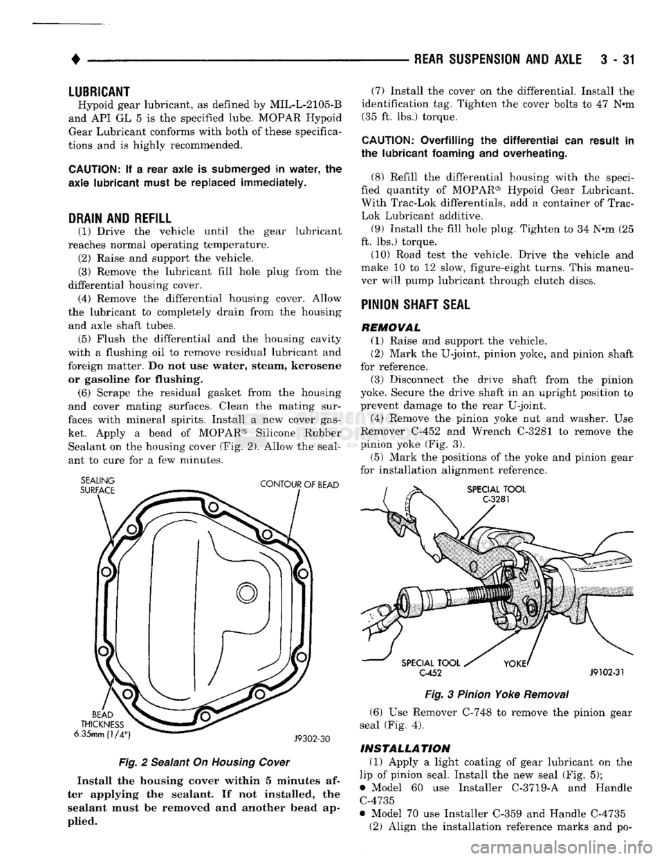
ket. Apply a bead of MOPAR® Silicone Rubber Sealant on the housing cover (Fig. 2). Allow the seal
ant to cure for a few minutes.
SEALING
SURFACE
CONTOUR
OF
BEAD
BEAD
THICKNESS
6.35mm
(1/4")
J9302-30
Fig.
2 Sealant On Housing Cower
Install
the
housing
cover
within 5
minutes
af
ter
applying
the
sealant.
If not
installed,
the
sealant
must be
removed
and another
bead
ap
plied.
(7) Install the cover on the differential. Install the
identification tag. Tighten the cover bolts to 47 Nem (35 ft. lbs.) torque.
CAUTION:
Overfilling
the differential" can
result
in
the
lubricant
foaming
and
overheating.
(8) Refill the differential housing with the speci
fied quantity of MOPAR® Hypoid Gear Lubricant.
With Trac-Lok differentials, add a container of Trac-
Lok Lubricant additive.
(9) Install the fill hole plug. Tighten to 34 N-m (25
ft. lbs.) torque.
(10) Road test the vehicle. Drive the vehicle and
make 10 to 12 slow, figure-eight turns. This maneu
ver will pump lubricant through clutch discs.
PINION
SHAFT
SEAL
REMOVAL
(1) Raise and support the vehicle.
(2) Mark the U-joint, pinion yoke, and pinion shaft
for reference.
(3) Disconnect the drive shaft from the pinion
yoke. Secure the drive shaft in an upright position to
prevent damage to the rear U-joint.
(4) Remove the pinion yoke nut and washer. Use
Remover C-452 and Wrench C-3281 to remove the
pinion yoke (Fig. 3).
(5) Mark the positions of the yoke and pinion gear
for installation alignment reference.
SPECIAL
TOOL
C-3281
SPECIAL
TOOL
C-452
J9102-31
Fig.
3 Pinion Yoke
Removal
(6) Use Remover C-748 to remove the pinion gear
seal (Fig. 4).
INSTALLATION
(1) Apply a light coating of gear lubricant on the
lip of pinion seal. Install the new seal (Fig. 5);
• Model 60 use Installer C-3719-A and Handle C-4735
• Model 70 use Installer C-359 and Handle C-4735 (2) Align the installation reference marks and po-