1993 DODGE TRUCK air conditioning
[x] Cancel search: air conditioningPage 291 of 1502

7 - 20
COOLING
SYSTEM
•
HOSE
CLAMP
HOSE
J9207-36
Fig.
16
Hose
Clamp
Tool
WITH AIR
CONDITIONING
(A/C)
REMOVAL
If equipped with A/C, the generator and A/C com
pressor along with their common mounting bracket (Fig. 17) must be partially removed. Removing the
generator or A/C compressor from their mounting
bracket is not necessary. Also, discharging the A/C system is not necessary. Do not remove any refrig
erant lines from A/C compressor.
SUPPORT BRACKET (ROD)
GENERATOR/COMPRESSOR
MOUNTING
BRACKET
J9307-66
Fig.
17 Generator—A/C
Compressor
Mounting
Bracket—
Typical
WARNING;
THE A/C
SYSTEM
IS
UNDER
PRESSURE
EVEN
WITH
THE
ENGINE OFF. REFER
TO
REFRIG
ERANT
WARNINGS
IN
GROUP
24,
HEATING
AND
AIR
CONDITIONING.
(1) Disconnect negative battery cable from battery. (2) Partially drain cooling system. Refer to Drain
ing Cooling System in this group.
Do not waste reusable coolant. If the solution is
clean, drain the coolant into a clean container for re
use.
(3) Remove upper radiator hose clamp at radiator.
Special Clamp Tool number 6094 (Fig. 16) may be
used to remove the constant tension clamps. Remove
hose at radiator.
(4) Disconnect throttle cable from clip at radiator
fan shroud. (5) Unplug wiring harness from A/C compressor.
(6) Remove the air cleaner assembly.
(7) Remove accessory drive belt. Refer to Belt Re
moval/Installation in the Engine Accessory Drive
Belt section of this group.
(8) 3.9L/5.2L/5.9L LDC-Gas: The drive belt idler
pulley must be removed to gain access to one of the
A/C compressor/generator bracket mounting bolts. Remove the idler pulley bolt and remove idler pulley (Fig. 18).
GENERATOR/COMPRESSOR
AND
BRACKET
SUPPORT BRACKET
IGNITION
COIL
BRACKET
Fig.
18 Idler Pulley-3.9U5.2U5.9L
LDC-Gas
Engine
5.9L HDC-Gas: The automatic belt tensioner/pul-
ley assembly must be removed to gain access to one
of the A/C compressor/generator bracket mounting
bolts.
Remove the tensioner mounting bolt (Fig. 19) and remove tensioner.
(9) Remove the engine oil dipstick tube mounting
bolt at the side of the A/C-generator mounting
bracket.
(10) Disconnect throttle body control cables. Refer
to Accelerator Pedal and Throttle Cable in Group 14,
Fuel System.
Page 295 of 1502
7 - 24
COOLING SYSTEM
• If the thermostat is being replaced, be sure that
the replacement is the specified thermostat for the vehicle model and engine type. Factory installed thermostat housings on 3.9L/5.2L/
5.9L engines are installed on a gasket with an anti-
stick coating. This will aid in gasket removal and
clean-up.
(1) Disconnect negative battery cable at battery.
(2) Drain cooling system until coolant level is be
low thermostat. Refer to Draining Cooling System in
this group. If not equipped with air conditioning, pro ceed to step number 4.
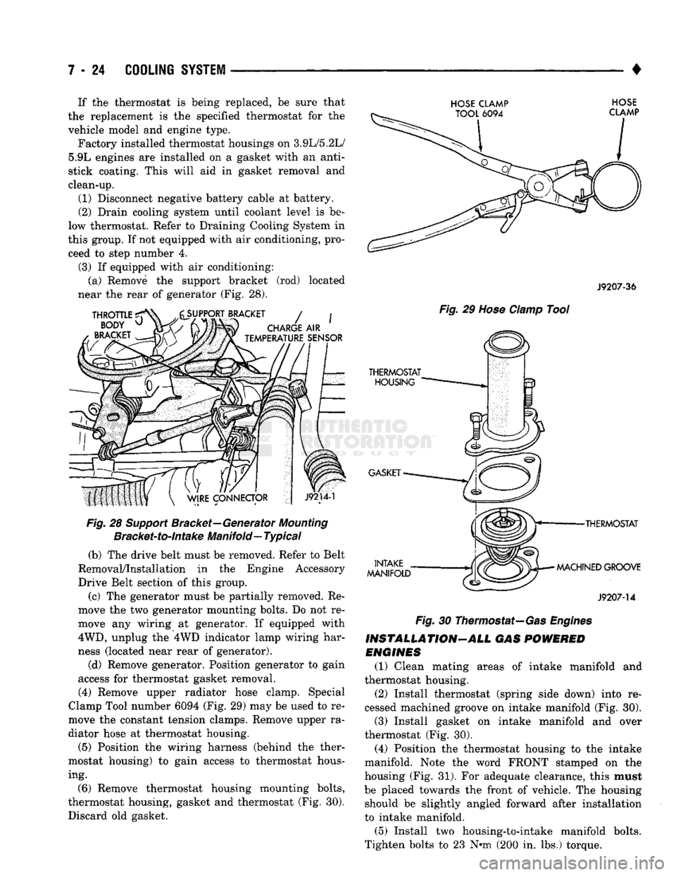
(3) If equipped with air conditioning: (a) Remove the support bracket (rod) located
near the rear of generator (Fig. 28).
Fig.
28
Support
Bracket—Generator
Mounting
Bracket-to-intake
Manifold—
Typical
(b) The drive belt must be removed. Refer to Belt
Removal/Installation in the Engine Accessory
Drive Belt section of this group.
(c) The generator must be partially removed. Re
move the two generator mounting bolts. Do not re
move any wiring at generator. If equipped with
4WD,
unplug the 4WD indicator lamp wiring har
ness (located near rear of generator).
(d) Remove generator. Position generator to gain
access for thermostat gasket removal.
(4) Remove upper radiator hose clamp. Special
Clamp Tool number 6094 (Fig. 29) may be used to re
move the constant tension clamps. Remove upper ra
diator hose at thermostat housing.
(5) Position the wiring harness (behind the ther
mostat housing) to gain access to thermostat hous ing.
(6) Remove thermostat housing mounting bolts,
thermostat housing, gasket and thermostat (Fig. 30). Discard old gasket.
HOSE CLAMP HOSE
J9207-36
Fig.
29
Hose
Clamp
Tool
•THERMOSTAT
MACHINED GROOVE
J9207-14
Fig.
30 Thermostat—Gas
Engines
INSTALLATION-ALL GAS
POWERED
ENGINES
(1) Clean mating areas of intake manifold and
thermostat housing. (2) Install thermostat (spring side down) into re
cessed machined groove on intake manifold (Fig. 30).
(3) Install gasket on intake manifold and over
thermostat (Fig. 30).
(4) Position the thermostat housing to the intake
manifold. Note the word FRONT stamped on the
housing (Fig. 31). For adequate clearance, this must
be placed towards the front of vehicle. The housing should be slightly angled forward after installation
to intake manifold.
(5) Install two housing-to-intake manifold bolts.
Tighten bolts to 23 N-m (200 in. lbs.) torque.
Page 306 of 1502
•
COOLING
SYSTEM
7 - 35
HOSE
CLAMP TOOL
6094
HOSE
CLAMP
J9207-36
Fig.
48
Hose
damp Tool
TRANSMISSION
OIL
COOLER—EXCEPT DIESEL
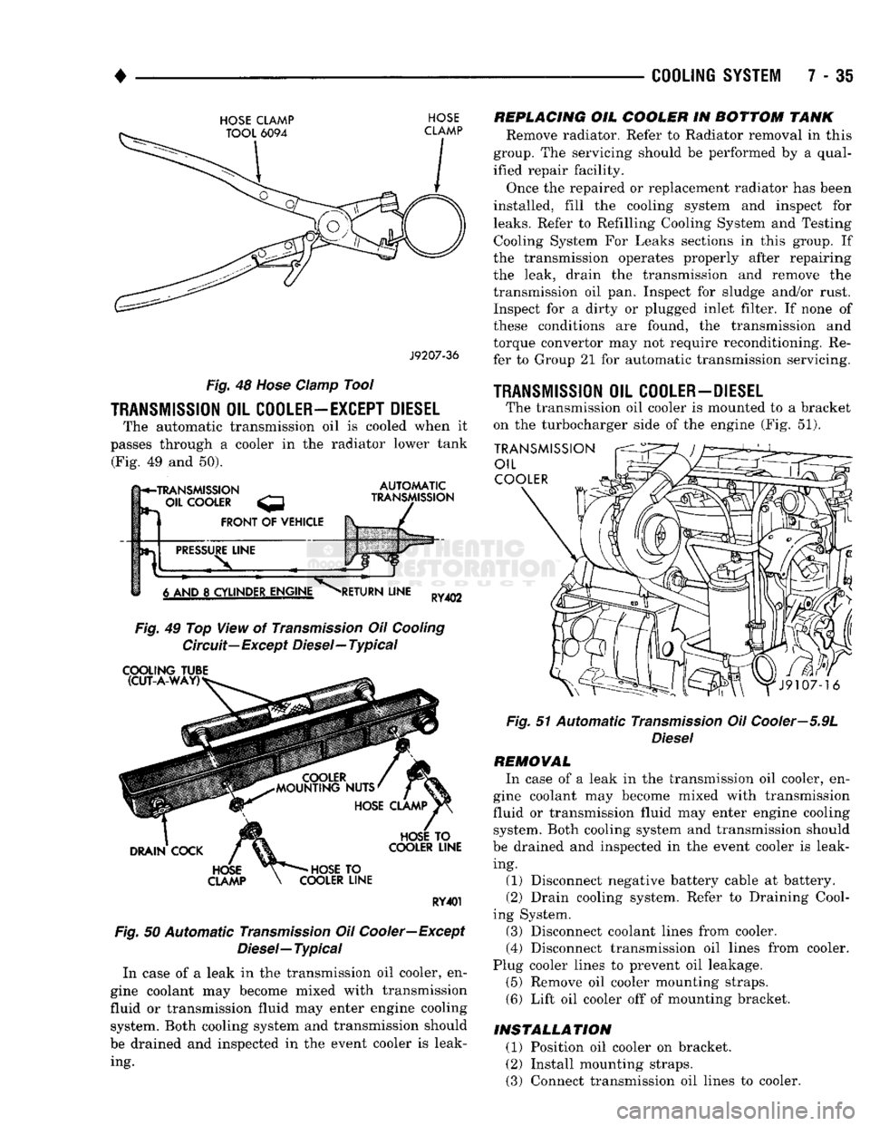
The automatic transmission oil is cooled when it
passes through a cooler in the radiator lower tank (Fig. 49 and 50).
h*-TRANSMISSION
- OIL
COOLER
FRONT
OF
VEHICLE
AUTOMATIC
TRANSMISSION
PRESSURE
LINE
6 AND
8
CYLINDER ENGINE
RETURN
LINE
RY402
Fig.
49 Top View of
Transmission
Oil
Cooling
Circuit—Except Diesel—Typical
COOLING
TUBE (CUT-A-WAY)
DRAIN
COCK
HOSE
CLAMP
HOSE
TO
COOLER
LINE
HOSE
TO
COOLER
LINE
RY401
Fig.
50 Automatic
Transmission
Oil Cooler—Except
Diesel—
Typical
In case of a leak in the transmission oil cooler, en
gine coolant may become mixed with transmission
fluid or transmission fluid may enter engine cooling system. Both cooling system and transmission should
be drained and inspected in the event cooler is leak ing.
REPLACING
OIL
COOLER
IN
BOTTOM
TANK
Remove radiator. Refer to Radiator removal in this
group. The servicing should be performed by a qual
ified repair facility.
Once the repaired or replacement radiator has been
installed, fill the cooling system and inspect for
leaks.
Refer to Refilling Cooling System and Testing Cooling System For Leaks sections in this group. If
the transmission operates properly after repairing
the leak, drain the transmission and remove the
transmission oil pan. Inspect for sludge and/or rust. Inspect for a dirty or plugged inlet filter. If none of
these conditions are found, the transmission and
torque convertor may not require reconditioning. Re
fer to Group 21 for automatic transmission servicing.
1RANSMISSI0N
OIL
COOLER-DIESEL
The transmission oil cooler is mounted to a bracket
on the turbocharger side of the engine (Fig. 51).
TRANSMISSION
OIL
COOLER
Fig.
51 Automatic
Transmission
Oil Cooler—5.9L
Diesel
REMOVAL
In case of a leak in the transmission oil cooler, en
gine coolant may become mixed with transmission
fluid or transmission fluid may enter engine cooling system. Both cooling system and transmission should
be drained and inspected in the event cooler is leak ing. (1) Disconnect negative battery cable at battery.
(2) Drain cooling system. Refer to Draining Cool
ing System. (3) Disconnect coolant lines from cooler.
(4) Disconnect transmission oil lines from cooler.
Plug cooler lines to prevent oil leakage. (5) Remove oil cooler mounting straps.
(6) Lift oil cooler off of mounting bracket.
INSTALLATION
(1) Position oil cooler on bracket.
(2) Install mounting straps.
(3) Connect transmission oil lines to cooler.
Page 311 of 1502
ENGINE ACCESSORY DRIVE BELTS
INDEX
page
Automatic Belt Tensioner
45
Belt Diagnosis
40
Belt Removal/Installation
. 40
page
Belt Schematics
40
Belt Tension
40
General
Information
40
GENERAL
INFORMATION
All vehicles are available with either
a
3.9L (V-6),
a 5.2L (V-8),
a
5.9L (gas V-8) or
a
5.9L (in-line 6 cyl
inder diesel) engine. The accessory drive components
are
operated
by a
single, crankshaft driven, serpentine drive belt on all
engines. An automatic belt tensioner
is
used to main
tain correct belt tension
at all
times. Refer
to
Auto matic Belt Tensioner proceeding
in
this group.
BELT DIAGNOSIS SERPENTINE DRIVE BELT DIAGNOSIS-ALL
ENGINES
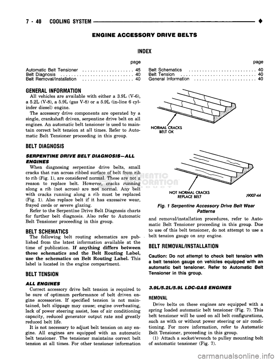
When diagnosing serpentine drive belts, small
cracks that run across ribbed surface of belt from rib
to rib (Fig. 1), are considered normal. These are not
a
reason
to
replace belt. However, cracks running along
a rib (not
across)
are not
normal.
Any
belt
with cracks running along
a rib
must
be
replaced (Fig.
1).
Also replace belt
if it has
excessive wear,
frayed cords
or
severe glazing.
Refer to the Serpentine Drive Belt Diagnosis charts
for further belt diagnosis. Also refer
to
Automatic Belt Tensioner proceeding
in
this group.
BELT SCHEMATICS
The following belt routing schematics
are
pub
lished from
the
latest information available
at the
time
of
publication.
If
anything differs between
these schematics
and the
Belt Routing Label,
use
the
schematics
on
Belt Routing Label. This
label
is
located
in
the engine compartment.
BELT TENSION
ALL
ENGINES
Correct accessory drive belt tension
is
required
to
be sure
of
optimum performance
of
belt driven
en
gine accessories.
If
specified tension
is not
main
tained, belt slippage may cause; engine overheating, lack
of
power steering assist, loss
of
air conditioning
capacity, reduced generator output rate and greatly
reduced belt life.
It
is
not necessary
to
adjust belt tension on any en
gine.
All
engines
are
equipped with
an
automatic
belt tensioner. The tensioner maintains correct belt tension
at all
times. For other tensioner information
NORMAL CRACKS
BELT
OK
NOT NORMAL CRACKS
REPLACE
BELT
J9007-44
Fig. 1 Serpentine Accessory Drive Belt Wear Patterns
and removal/installation procedures, refer
to
Auto
matic Belt Tensioner proceeding
in
this group.
Due
to use
of
this belt tensioner, do not attempt
to
use
a
belt tension gauge
on
any engine.
BELT REMOVAL/INSTALLATION
Caution:
Do not
attempt
to
check belt tension with
a
belt
tension gauge
on
vehicles equipped with
an
automatic belt tensioner. Refer
to
Automatic Belt
Tensioner
in
this
group.
3.9L/5,2U5*9L
LDC-GAS ENGINES
REMOVAL
Drive belts
on
these engines
are
equipped with
a
spring loaded automatic belt tensioner (Fig.
7).
This
belt tensioner will
be
used on
all
belt configurations, such
as
with
or
without power steering
or
air condi
tioning.
For
more information, refer
to
Automatic Belt Tensioner, proceeding
in
this group.
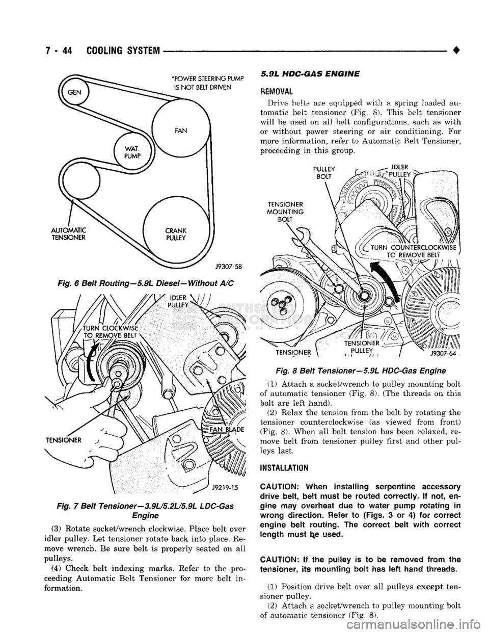
(1) Attach
a
socket/wrench
to
pulley mounting bolt
of automatic tensioner (Fig.
7).
Page 315 of 1502
7 - 44
COOLING
SYSTEM
•
Fig.
6 Belt Routing-5.9L Diesel-Without A/C
Fig.
7 Belt Tensioner-3.9L/5.2U5.9L
LDC-Gas
Engine
(3)
Rotate socket/wrench clockwise. Place belt over
idler pulley. Let tensioner rotate back into place. Re
move wrench. Be sure belt is properly seated on all
pulleys.
(4)
Check belt indexing marks. Refer to the pro
ceeding Automatic Belt Tensioner for more belt in
formation. 5.9L
HDC-GAS
ENGINE
REMOVAL
Drive belts are equipped with a spring loaded au
tomatic belt tensioner (Fig. 8). This belt tensioner
will be used on all belt configurations, such as with or without power steering or air conditioning. For
more information, refer to Automatic Belt Tensioner,
proceeding in this group.
Fig.
8 Belt Tensioner—5.9L
HDC-Gas Engine
(1) Attach a socket/wrench to pulley mounting bolt
of automatic tensioner (Fig. 8). (The threads on this
bolt are left hand).
(2) Relax the tension from the belt by rotating the
tensioner counterclockwise (as viewed from front) (Fig. 8). When all belt tension has been relaxed, re
move belt from tensioner pulley first and other pul leys last.
INSTALLATION
CAUTION:
When installing serpentine
accessory
drive belt, belt must
be
routed correctly.
If not, en
gine
may
overheat
due to
water pump rotating
in
wrong
direction. Refer
to
(Figs.
3 or 4) for
correct
engine
belt routing.
The
correct belt with correct length must
t^e
used.
CAUTION:
if the
pulley
is to be
removed from
the
tensioner,
its
mounting bolt
has left
hand threads.
(1) Position drive belt over all pulleys except ten
sioner pulley. (2) Attach a socket/wrench to pulley mounting bolt
of automatic tensioner (Fig. 8).
Page 316 of 1502
•
COOLING
SYSTEM
7 - 45 (3) Rotate socket/wrench counterclockwise. Install
belt over tensioner pulley. Let tensioner rotate back into place. Remove wrench. Be sure belt is properly
seated on all pulleys.
5«9L
DIESEL ENGINE
REMOVAL
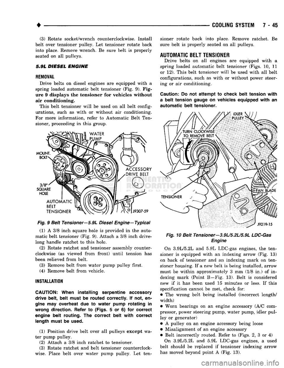
Drive belts on diesel engines are equipped with a
spring loaded automatic belt tensioner (Fig. 9). Fig
ure 9 displays the tensioner for vehicles without air conditioning.
This belt tensioner will be used on all belt config
urations, such as with or without air conditioning.
For more information, refer to Automatic Belt Ten sioner, proceeding in this group.
Fig.
9 Belt Tensioner—5.9L
Diesel
Engine—Typical
(1) A 3/8 inch square hole is provided in the auto
matic belt tensioner (Fig. 9). Attach a 3/8 inch drive-
long handle ratchet to this hole.
(2) Rotate ratchet and tensioner assembly counter
clockwise (as viewed from front) until tension has
been relieved from belt.
(3) Remove belt from water pump pulley first.
(4) Remove belt from vehicle.
INSTALLATION
CAUTION:
When installing serpentine
accessory
drive belt, belt must
be
routed correctly.
If not, en
gine
may
overheat
due to
water pump rotating
in
wrong
direction. Refer
to
(Figs.
5 or 6) for
correct
engine
belt routing.
The
correct belt with correct
length
must
be
used.
(1) Position drive belt over all pulleys except wa
ter pump pulley. (2) Attach a 3/8 inch ratchet to tensioner.
(3) Rotate ratchet and belt tensioner counterclock
wise.
Place belt over water pump pulley. Let ten sioner rotate back into place. Remove ratchet. Be
sure belt is properly seated on all pulleys.
AUTOMATIC
BELT
TENSIONER
Drive belts on all engines are equipped with a
spring loaded automatic belt tensioner (Figs. 10, 11
or 12). This belt tensioner will be used with all belt configurations, such as with or without power steer
ing or air conditioning.
Caution:
Do not
attempt
to
check belt tension with
a
belt tension
gauge
on
vehicles equipped with
an
automatic
belt tensioner. Fig.
10 Belt Tensioner—3.9U5.2U5.9L
LDC-Gas
Engine
On 3.9L/5.2L and 5.9L LDC-gas engines, the ten
sioner is equipped with an indexing arrow (Fig. 13)
on back of tensioner and an indexing mark on ten
sioner housing. If a new belt is being installed, arrow
must be within approximately 3 mm (1/8 in.) of in dexing mark (Point B—Fig. 13). Belt is considered
new if it has been used 15 minutes or less. If this
specification cannot be met, check for:
• The wrong belt being installed (incorrect length/
width)
• Worn bearings on an engine accessory (A/C com
pressor, power steering pump, water pump, idler pul ley or generator)
• A pulley on an engine accessory being loose
• Misalignment of an engine accessory
• Belt incorrectly routed. Refer to (Figs. 2, 3 or 4) On 3.9L/5.2L and 5.9L LDC-gas engines, a used
belt should be replaced if tensioner indexing arrow
has moved beyond point A (Fig. 13).
Page 361 of 1502
8D
- 10
IGNITION
SYSTEMS
• Arcing at the tower will carbonize the cable boot,
which if it is connected to a new ignition coil, will cause the coil to fail. If the secondary coil cable shows any signs of dam
age,
it should be replaced with a new cable and new
terminal. Carbon tracking on the old cable can cause
arcing and the failure of a new ignition coil.
ENGINE
COOLANT
TEMPERATURE
SENSOR
TEST
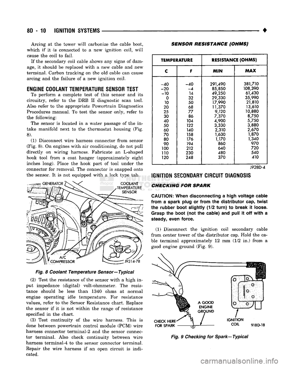
To perform a complete test of this sensor and its
circuitry, refer to the DRB II diagnostic scan tool.
Also refer to the appropriate Powertrain Diagnostics
Procedures manual. To test the sensor only, refer to
the following: The sensor is located in a water passage of the in
take manifold next to the thermostat housing (Fig.
8).
(1) Disconnect wire harness connector from sensor
(Fig. 8). On engines with air conditioning, do not pull
directly on wiring harness. Fabricate an L-shaped
hook tool from a coat hanger (approximately eight inches long). Place the hook part of tool under the
connector for removal. The connector is snapped onto
the sensor. It is not equipped with a lock type tab.
COOLANT
TEMPERATURE
SENSOR
SENSOR RESISTANCE (OHMSJ
V
J9314-78
Fig. 8 Coolant Temperature Sensor—Typical (2) Test the resistance of the sensor with a high in
put impedance (digital) volt-ohmmeter. The resis tance should be less than 1340 ohms at normal
engine operating idle temperature. For resistance
values, refer to the Sensor Resistance chart. Replace
the sensor if it is not within the range of resistance specified in the chart.
(3) Test continuity of the wire harness. This is
done between powertrain control module (PCM) wire
harness connector terminal-2 and the sensor connec
tor terminal. Also check continuity between wire harness terminal-4 to the sensor connector terminal. Repair the wire harness if an open circuit is indi
cated.
TEMPERATURE
RESISTANCE
(OHMS)
C
F
MIN
MAX
-40 -40 291,490 381,710
-20
-4
85,850
108,390
-10 14
49,250 61,430
0
32 29,330
35,990
10 50 17,990 21,810
20 68 11,370 13,610
25
77 9,120 10,880
30 86
7,370
8,750
40 104
4,900
5,750
50 122
3,330 3,880
60 140 2,310
2,670
70 158
1,630 1,870
80 176
1,170 1,340
90 194
860
970
100 212 640
720
110 230 480 540
120 248 370 410
J928D-4
IGNITION
SECONDARY
CIRCUIT
DIAGNOSIS
CHECKING FOR SPARK
CAUTION:
When
disconnecting a
high
voltage
cable
from
a spark
plug
or
from
the
distributor
cap,
twist
the rubber
boot
slightly
(1/2
turn)
to
break
it
loose.
Grasp
the
boot
(not the cable) and
pull
it off
with
a
steady,
even force.
(1) Disconnect the ignition coil secondary cable
from center tower of the distributor cap. Hold the ca
ble terminal approximately 12 mm (1/2 in.) from a good engine ground (Fig. 9).
CHECK
HERE
FOR
SPARK
IGNITION
COIL
918D-18
Fig. 9 Checking for Spark—Typical
Page 371 of 1502
8D
- 20
IGNITION
SYSTEMS
•
ENGINE
COOLANT
TEMPERATURE
SENSOR
WARNING: HOT, PRESSURIZED COOLANT CAN CAUSE INJURY BY SCALDING. COOLING SYSTEM MUST BE PARTIALLY DRAINED BEFORE REMOV
ING THE COOLANT TEMPERATURE SENSOR. RE
FER TO GROUP 7, COOLING.
REMOVAL
(1) Partially drain cooling system. Refer to Group
7, Cooling.
(2)
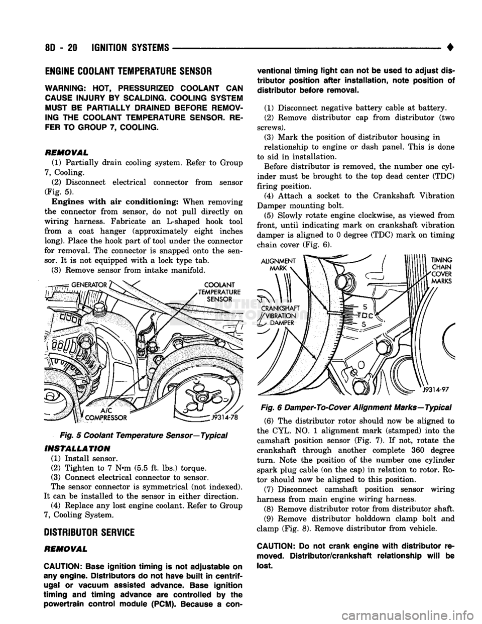
Disconnect electrical connector from sensor
(Fig. 5). Engines with air conditioning: When removing
the connector from sensor, do not pull directly on
wiring harness. Fabricate an L-shaped hook tool
from a coat hanger (approximately eight inches
long).
Place the hook part of tool under the connector
for removal. The connector is snapped onto the sen sor. It is not equipped with a lock type tab.
(3) Remove sensor from intake manifold.
Fig. 5 Coolant Temperature
Sensor—
Typical
INSTALLATION
(1) Install sensor.
(2) Tighten to 7 Nnn (5.5 ft. lbs.) torque.
(3) Connect electrical connector to sensor.
The sensor connector is symmetrical (not indexed).
It can be installed to the sensor in either direction. (4) Replace any lost engine coolant. Refer to Group
7, Cooling System.
DISTRIBUTOR
SERVICE
REMOVAL
CAUTION:
Base
ignition timing
is not
adjustable
on
any
engine. Distributors
do not
have
built
in
centrif
ugal
or
vacuum assisted advance.
Base
ignition
timing
and
timing advance
are
controlled
by the
powertrain control module
(PCM).
Because
a
con
ventional timing light can
not be
used
to
adjust
dis
tributor
position
after
installation, note position
of
distributor before removal.
(1) Disconnect negative battery cable at battery.
(2) Remove distributor cap from distributor (two
screws).
(3) Mark the position of distributor housing in
relationship to engine or dash panel. This is done
to aid in installation. Before distributor is removed, the number one cyl
inder must be brought to the top dead center (TDC)
firing position. (4) Attach a socket to the Crankshaft Vibration
Damper mounting bolt.
(5) Slowly rotate engine clockwise, as viewed from
front, until indicating mark on crankshaft vibration damper is aligned to 0 degree (TDC) mark on timing
chain cover (Fig. 6).
Fig. 6 Damper-To-Cover Alignment Marks—Typical (6) The distributor rotor should now be aligned to
the CYL. NO. 1 alignment mark (stamped) into the camshaft position sensor (Fig. 7). If not, rotate the
crankshaft through another complete 360 degree
turn.
Note the position of the number one cylinder spark plug cable (on the cap) in relation to rotor. Ro
tor should now be aligned to this position.
(7) Disconnect camshaft position sensor wiring
harness from main engine wiring harness.
(8) Remove distributor rotor from distributor shaft. (9) Remove distributor holddown clamp bolt and
clamp (Fig. 8). Remove distributor from vehicle.
CAUTION: Do not
crank engine
with
distributor
re
moved.
Distributor/crankshaft relationship
will
be
lost.