1993 DODGE TRUCK air conditioning
[x] Cancel search: air conditioningPage 398 of 1502
INSTRUMENT
PANEL
AND
GAUGES
8E - 17
HEATER
A/C
CONTROL
REMOVAL
(1) Remove map lamp.
(2) Remove cluster bezel (refer to Cluster Bezel Re
moval).
(3) Remove 2 control attaching screws.
(4) Pull control rearward.
(5) Disconnect blower switch wiring.
(6) Disconnect wires to pushbutton switch (three
connectors). (7) Disconnect illumination lamp.
(8) Disconnect vacuum harness.
(9) Disconnect temperature cable.
(10) Remove control.
INSTALLATION
(1) Position control near panel.
(2) Connect temperature cable (see Group 24 -
Heating and Air Conditioning).
(3) Connect vacuum harness. (4) Connect illumination lamp.
(5) Attach 3 wire connectors to pushbutton switch.
(6) Connect wires to blower motor switch.
(7) Push control into panel.
(8) Install 2 control mounting screws.
(9) Install cluster bezel.
(10) Install map lamp.
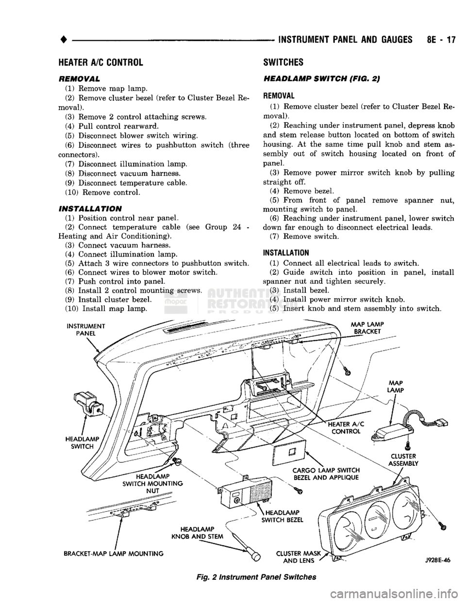
INSTRUMENT
PANEL SWITCHES
HEADLAMP
SWITCH
(FIG. 2)
REMOVAL
(1) Remove cluster bezel (refer to Cluster Bezel Re
moval).
(2) Reaching under instrument panel, depress knob
and stem release button located on bottom of switch
housing. At the same time pull knob and stem as sembly out of switch housing located on front of
panel.
(3) Remove power mirror switch knob by pulling
straight off.
(4) Remove bezel.
(5) From front of panel remove spanner nut,
mounting switch to panel. (6) Reaching under instrument panel, lower switch
down far enough to disconnect electrical leads. (7) Remove switch.
INSTALLATION
(1) Connect all electrical leads to switch.
(2) Guide switch into position in panel, install
spanner nut and tighten securely.
(3) Install bezel.
(4) Install power mirror switch knob.
(5) Insert knob and stem assembly into switch.
AAAP LAMP
BRACKET
HEADLAMP SWITCH
CLUSTER
ASSEMBLY
HEADLAMP
SWITCH MOUNTING NUT
CARGO
LAMP SWITCH
BEZEL
AND APPLIQUE
HEADLAMP
KNOB AND STEM
BRACKET-MAP LAMP MOUNTING HEADLAMP
SWITCH BEZEL
CLUSTER AAASK AND LENS
J928E-46
Fig.
2 Instrument
Panel
Switches
Page 477 of 1502
8W
- 2
WIRING
DIAGRAMS
•
WIRE CODE
IDENTIFICATION
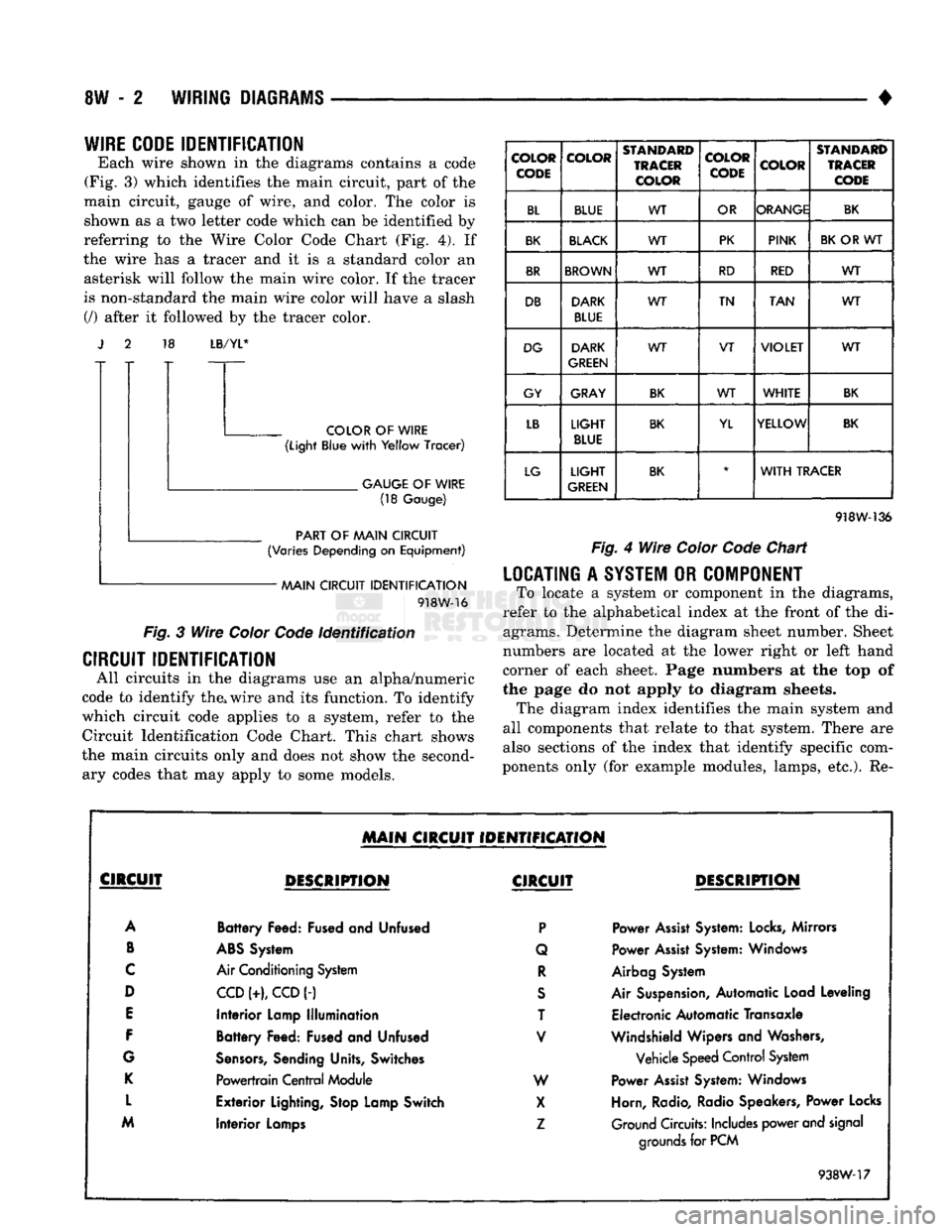
Each wire shown in the diagrams contains a code
(Fig. 3) which identifies the main circuit, part of the
main circuit, gauge of wire, and color. The color is shown as a two letter code which can be identified by
referring to the Wire Color Code Chart (Fig. 4). If
the wire has a tracer and it is a standard color an asterisk will follow the main wire color. If the tracer
is non-standard the main wire color will have a slash (/) after it followed by the tracer color. 18
LB/YL*
COLOR
OF
WIRE
(Light
Blue
with
Yellow
Tracer)
.
GAUGE
OF
WIRE
(18
Gauge)
PART
OF
AAAIN CIRCUIT
(Varies
Depending
on
Equipment)
AAAIN CIRCUIT
IDENTIFICATION
918W-16
Fig.
3
Wire
Color
Code
Identification
CIRCUIT IDENTIFICATION
All circuits in the diagrams use an alpha/numeric
code to identify the, wire and its function. To identify
which circuit code applies to a system, refer to the
Circuit Identification Code Chart. This chart shows
the main circuits only and does not show the second ary codes that may apply to some models.
COLOR
CODE COLOR
STANDARD
TRACER
COLOR COLOR
CODE
COLOR
STANDARD
TRACER
CODE
BL BLUE WT
OR ORANGE
BK
BK
BLACK
WT PK
PINK
BK
OR WT
BR
BROWN
WT RD
RED WT
DB DARK
BLUE WT
TN
TAN WT
DG DARK
GREEN WT
VT
VIOLET
WT
GY GRAY
BK
WT
WHITE
BK
LB
LIGHT
BLUE
BK
YL YELLOW
BK
LG
LIGHT
GREEN
BK
*
WITH
TRACER
918W-136
Fig.
4
Wire
Color
Code
Chart
LOCATING
A
SYSTEM
OR
COMPONENT
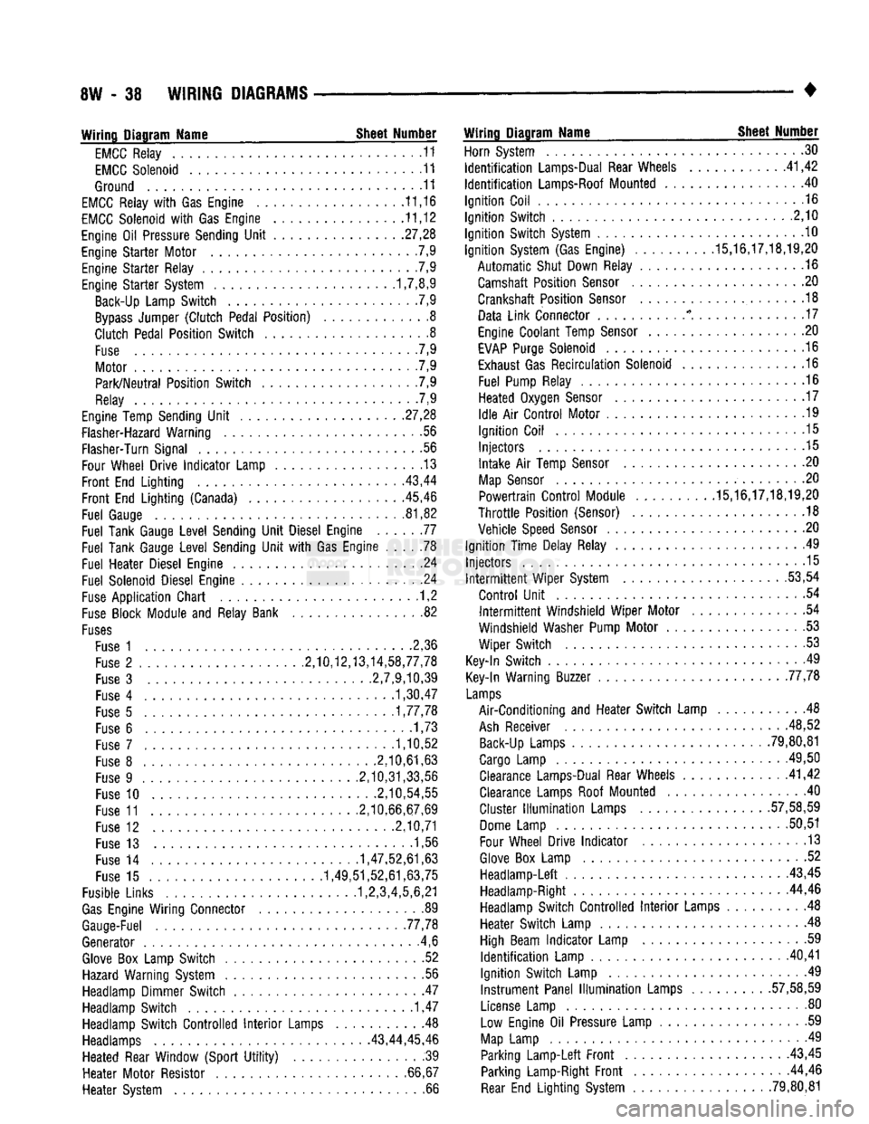
To locate a system or component in the diagrams,
refer to the alphabetical index at the front of the di agrams. Determine the diagram sheet number. Sheet
numbers are located at the lower right or left hand
corner of each sheet. Page numbers at the top of
the page do not apply to diagram sheets. The diagram index identifies the main system and
all components that relate to that system. There are
also sections of the index that identify specific com
ponents only (for example modules, lamps, etc.). Re-
MAIN
CIRCUIT IDENTIFICATION
CIRCUIT
DESCRIPTION
CIRCUIT
DESCRIPTION
A
Battery
Feed: Fused and Unfused
P
Power
Assist
System:
Locks,
Mirrors
B
ABS
System Q Power
Assist
System: Windows
C
Air Conditioning System
R
Airbag System
D
CCD
(+),
CCD
(-)
S
Air Suspension, Automatic Load Leveling
E
Interior
Lamp
Illumination
T Electronic Automatic Transaxle
F
Battery
Feed: Fused and Unfused
V
Windshield Wipers and Washers,
G
Sensors,
Sending Units, Switches Vehicle Speed Control System
K
Powertrain
Central
Module W Power
Assist
System: Windows
L
Exterior
Lighting, Stop Lamp Switch
X
Horn, Radio, Radio Speakers, Power Locks
M
Interior
Lamps
Z
Ground Circuits: Includes power and signal
Interior
Lamps
grounds
for PCM
938W-17
Page 513 of 1502
8W
- 38
WIRING
DIAGRAMS
• Wiring Diagram Name Sheet Number
EMCC
Relay
11
EMCC
Solenoid
11
Ground
11
EMCC
Relay
with Gas
Engine
11,16
EMCC
Solenoid
with Gas
Engine
11,12
Engine
Oil
Pressure Sending
Unit
.27,28
Engine
Starter
Motor
7,9
Engine
Starter
Relay
.7,9
Engine
Starter
System 1,7,8,9 Back-Up Lamp
Switch
.7,9
Bypass
Jumper
(Clutch
Pedal
Position)
8
Clutch
Pedal
Position
Switch
8
Fuse
. 7,9
Motor
7,9
Park/Neutral
Position
Switch
. .7,9
Relay
7,9
Engine Temp Sending
Unit
.
.27,28
Flasher-Hazard Warning
.56
Flasher-Turn Signal
56
Four Wheel
Drive
Indicator
Lamp
13
Front
End
Lighting
. .
.43,44
Front
End
Lighting
(Canada) 45,46
Fuel
Gauge
81,82
Fuel
Tank Gauge
Level
Sending
Unit
Diesel Engine
77
Fuel
Tank Gauge
Level
Sending
Unit
with Gas
Engine
78
Fuel
Heater
Diesel Engine
24
Fuel
Solenoid Diesel Engine
.24
Fuse
Application
Chart
1,2
Fuse
Block Module
and
Relay Bank
82
Fuses
Fuse
1 2,36
Fuse
2
.........
2,10,12,13,14,58,77,78
Fuse
3
2,7,9,10,39
Fuse
4
1,30,47
Fuse
5
1,77,78
Fuse
6
......
.1,73
Fuse
7
1,10,52
Fuse
8
.2,10,61,63
Fuse
9
.2,10,31,33,56
Fuse
10
.2,10,54,55
Fuse
11
2,10,66,67,69
Fuse
12
2,10,71
Fuse
13 1,56
Fuse
14
1,47,52,61,63
Fuse
15
1,49,51,52,61,63,75
Fusible Links 1,2,3,4,5,6,21
Gas
Engine
Wiring
Connector
89
Gauge-Fuel .77,78
Generator
.4,6
Glove
Box
Lamp
Switch
52
Hazard Warning System
. .56
Headlamp Dimmer
Switch
47
Headlamp
Switch
1,47
Headlamp
Switch
Controlled
Interior
Lamps
Headlamps 43,44,
Heated
Rear Window
(Sport
Utility)
Heater
Motor
Resistor
Heater
System Wiring Diagram Name Sheet Number
Horn System
30
Identification
Lamps-Dual Rear Wheels
41,42
Identification
Lamps-Roof Mounted
. 40
Ignition
Coil
.16
Ignition
Switch
.2,10
Ignition
Switch
System
10
Ignition
System (Gas Engine)
.........
.15,16,17,18,19,20
Automatic
Shut Down Relay
.16
Camshaft
Position
Sensor
20
Crankshaft
Position
Sensor
.18
Data
Link
Connector
* . . .17
Engine Coolant Temp
Sensor
20
EVAP
Purge Solenoid
16
Exhaust Gas
Recirculation
Solenoid
16
Fuel
Pump Relay
.16
Heated
Oxygen
Sensor
. . . 17
Idle
Air
Control
Motor
.19
Ignition
Coil
.15
Injectors
.15
Intake
Air
Temp
Sensor
. .20
Map
Sensor
. .20
Powertrain
Control
Module .15,16,17,18,19,20
Throttle
Position
(Sensor)
.18
Vehicle
Speed
Sensor
.20
Ignition
Time
Delay Relay
49
Injectors
.15 Intermittent
Wiper
System .53,54
Control
Unit
.54 Intermittent
Windshield
Wiper
Motor
54
Windshield
Washer Pump
Motor
53
Wiper
Switch
53
Key-In
Switch
49
Key-In Warning Buzzer 77,78
Lamps
Air-Conditioning
and
Heater
Switch
Lamp
48
Ash
Receiver .48,52 Back-Up Lamps
......
79,80,81
Cargo Lamp
.
.49,50 Clearance Lamps-Dual Rear Wheels .41,42
Clearance Lamps Roof Mounted
.40
Cluster
Illumination
Lamps
.
.57,58,59
Dome Lamp
50,51
Four Wheel
Drive
Indicator
.13
Glove
Box
Lamp
52
Headlamp-Left
43,45 Headlamp-Right 44,46
Headlamp
Switch
Controlled
Interior
Lamps
. 48
Heater
Switch
Lamp
.48
High Beam
Indicator
Lamp
.59
Identification
Lamp
.
.40,41
Ignition
Switch
Lamp
.49
Instrument
Panel
Illumination
Lamps
.
.57,58,59
License Lamp
. . . 80
.
.48 Low
Engine
Oil
Pressure Lamp
59
45,46
Map
Lamp
49
.
.39
Parking
Lamp-Left
Front
43,45
66,67 Parking Lamp-Right
Front
44,46 .
.66
Rear
End
Lighting
System .79,80,81
Page 526 of 1502
WIRING DIAGRAMS 8W - 51
TO CHARGING
SYSTEM
(SEE
SH 4,6)
T Al
12RD
49 TO HEATED REAR „
WINDOW SWITCH Y-
(SEE
SH 39) IGNITION SWITCH
(ON STEERING COLUMN) F20 18WT-
FUSE
#3
(20 AMP)
A21 14DB-(-
FUSE
#2 (5 AMP)
•Al 12RD TO
ENGINE
,
STARTER
Y-
SYSTEM
(SEE
SH 8,9) -A41 14YL-
50 -A2 12PK/BK
GROUND
(THRU STEERING COLUMN
A2 ATTACHMENT)
12PK
BK
X
TO CHARGING
SYSTEM
(SEE
SH 4,6) -F20 18WT
TO BACK-UP
LAMP SWITCH
(SEE
SH 7,9) >-G5 20DB/WT-£ TO
(SEE
SH 58)
14DB TO
OR
SPLICE
(SEE
SH 68)
GAS
T0
SPLICE
(SEE
SH 23)
DIESEL
FUSE
#11
(30 AMP) TO
AIR CONDITIONING AND HEATER FEED
(SEE
SH
66,67,69)
12BK/0R
FUSE
#12 (30 AMP
CIRCUIT
BREAKER)
CI
12DG-
F21 12TN- TO
<
POWER
^WINDOWS
(SEE
SH 71) Gil 20WT/BK
— Gil 20WT/BK-
20PK/BK-
A41 14YL A21 14DB Gil 20WT/BK Gil 20WT/BK
A2 12PK/BK
A22 12BK/0R
A3!
14BK/WT Al 12RD
FUSE
#7
(15 AMP)
FUSE
#8
(10 AMP)
F30
16RD TN X12
20RD WT
FUSE
#9
(20 AMP)
FUSE
#10 (20 AMP)
18DB—5
18DB-5
14RD TO
MESSAGE
CENTER
(SEE
SH 57)
DIESEL
ONLY
TO WIPER
SYSTEMS
(SEE
SH
54,55)
TO
BRAKE
WARNING LAMP SWITCH
(SEE
SH 31)
(GAS ENGINE)
Gil
20WT
BK
TO
MESSAGE
CENTER
(SEE
SH 58)
(GAS ENGINE)
TO CIGAR LIGHTER
(SEE
SH 52) TO RADIO TO TURN SIGNAL
(SEE
SH SYSTEM
61.63.65)
(SEE SH 56) TO R.W.A.L.
MODULE
(SEE
SH
31,33)
J938W-11
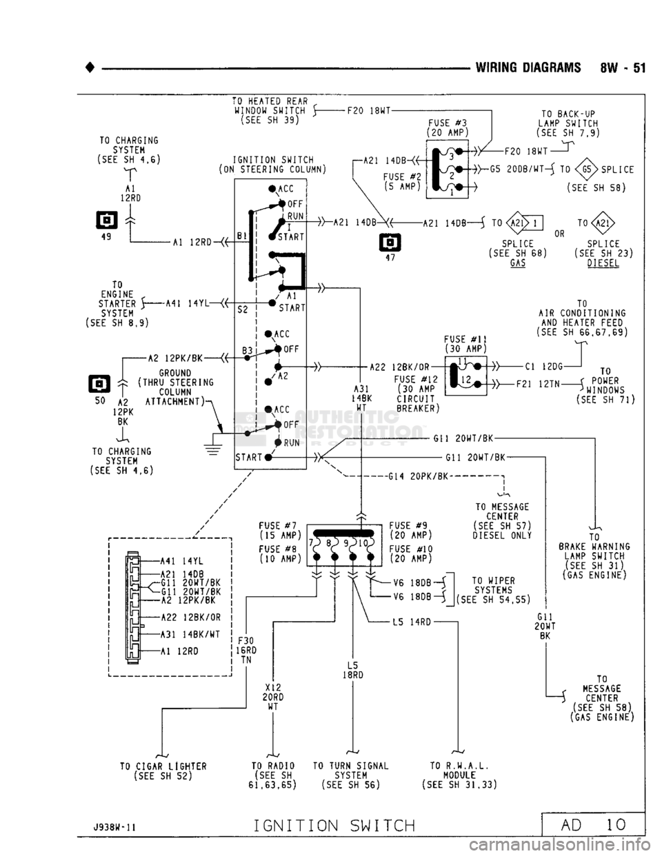
IGNITION SWITCH AD 10
Page 584 of 1502
•
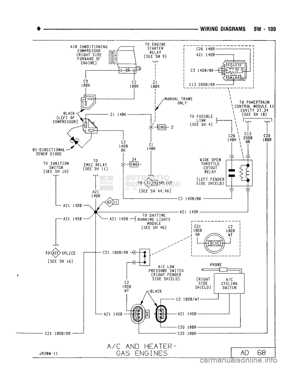
WIRING DIAGRAMS 8W - 109 AIR CONDITIONING
COMPRESSOR
(RIGHT SIDE FORWARD OF ENGINE)
C9
18BK C2
18BK TO ENGINE
STARTER
RELAY
(SEE
SH 9)
I
I I
!
Zl
18BK C26 14BR-
A21 14DB-
ca
hdb/bk^£3E5|H
C13 20DB/0R —J
^MANUAL TRANS ONLY
BLACK
(LEFT
OF
COMPRESSOR)
Zl 14BK-
\ TO POWERTRAIN
\ CONTROL MODULE II \ CAVITY
27,34
BI-DIRECTIONAL
ZENER
DIODE
TO IGNITION SWITCH
(SEE
SH 10)
:-4ENG]~
2 TO FUSIBLE
LINK
(SEE
SH 4)
(SEE
SH 18) Zl
14BK
TO
EMCC
RELAY
(SEE
SH 11) A21 14DB
I—A21
14DB 34
:-[ENG|~
T0
SPLICE
(SEE
SH
44.46)
TO
SPLICE
(SEE
SH 16)
C21 18DB/0R -C3 14DB/BK
r TO DAYTIME
A21 14DB —) RUNNING LIGHTS MODULE
(SEE
SH 46) A21 14DB WIDE OPEN
THROTTLE CUTOUT
RELAY
(LEFT
FENDER
SIDE
SHIELD' C21 18DB/0R ~
A/C
LOW
PRESSURE
SWITCH (RIGHT FENDER
SIDE
SHIELD)
•A21 14DB
PROBE
=£3:
(RIGHT
SIDE
SHIELD)
A/C
CYCLING SWITCH
C2 18DB/WT-
A21 14DB-
C20 18BR-
C20 18BR-
J938W-11
A/C
AND HEATER-
GAS
ENGINES AD 68
Page 586 of 1502
![DODGE TRUCK 1993 Service Repair Manual
WIRING
DIAGRAMS
8W
-
111
AIR CONDITIONING
COMPRESSOR
(RIGHT
SIDE
FORWARD
OF
ENGINE)
i
C26
14BR-
A21
14DB-
C3
i4DB/BK-ffi£^]QLJ
I86K
18BK
(LEFT
OF
COMPRESSOR)
Zl](/manual-img/12/56922/w960_56922-585.png "DODGE TRUCK 1993 Service Repair Manual
WIRING
DIAGRAMS
8W
-
111
AIR CONDITIONING
COMPRESSOR
(RIGHT
SIDE
FORWARD
OF
ENGINE)
i
C26
14BR-
A21
14DB-
C3
i4DB/BK-ffi£^]QLJ
I86K
18BK
(LEFT
OF
COMPRESSOR)
Zl")
WIRING
DIAGRAMS
8W
-
111
AIR CONDITIONING
COMPRESSOR
(RIGHT
SIDE
FORWARD
OF
ENGINE)
i
C26
14BR-
A21
14DB-
C3
i4DB/BK-ffi£^]QLJ
I86K
18BK
(LEFT
OF
COMPRESSOR)
Zl
18BK (RIGHT FENDER
SIDE
SHIELD) C13 20DB/0R-
TO FUSIBLE
„
LINK
$-
(SEE
SH 6) \ TO
POWERTRAIN
\
CONTROL MODULE
II
\
CAVITY
27,34
\ (SEE SH 26)
r
T
C20
18BR BI-DIRECTIONAL
ZENER
DIODE WIDE OPEN
THROTTLE CUTOUT
RELAY
(LEFT
FENDER
SIDE
SHIELD) C13 14DB/BK
Zl
14BK
TO
SPLICE
(SEE
SH 23)
C21
18DB/0R
TO
SPLICE
(SEE
SH 23)
SPLICE
(SEE
SH 21)
A/C
LOW
PRESSURE
SWITCH (RIGHT FENDER
SIDE
SHIELD)
A21
14DB
PROBE
(RIGHT
SIDE
SHIELD)
A/C
CYCLING SWITCH C2 18DB/0R-
A21
14DB-
C20 18BR-
C20 18BR-
J938W-H
A/C
AND
HEATER-
DIESEL
ENGINES
AD
70
Page 601 of 1502
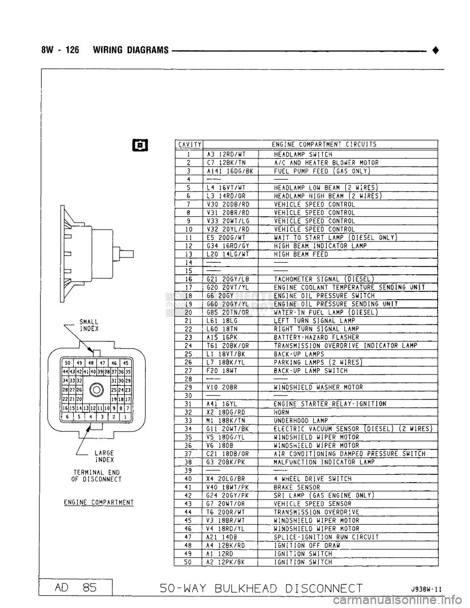
8W - 126
WIRING
DIAGRAMS
SMALL
INDEX
50 49 48
47
46 45
44 43 42 41
40 39
38 37
36 35
34 33 32
© 31
30 29
28 27
26
© 25
24 23
22 21
20 ©
19 18
17
16 15 14 13 12 11 10 9 8 7
6 5 4
3 2
1
LARGE
INDEX TERMINAL END
OF DISCONNECT
ENGINE COMPARTMENT CAVITY
1
10
11
12
13
14 15
16
17
18 19
20
21
22
23
24
25
26
27
28
29
30 31
32 33
34
35
36
37
38
39 40
41
42
43
44
45
46
47
48
50 ENGINE COMPARTMENT CIRCUITS
A3 12RD/WT C7 12BK/TN
A141 16DG/BK
L4
16VT/WT
L3 14RD/0R
V30 20DB/RD
V31 20BR/RD V33
20WT/LG
V32 20YL/RD
E5
20DG/WT
G34 16RD/GY
L20
14LG/WT
G21 20GY/LB G20
20VT/YL
G6 20GY
G60 20GY/YL
G85 20TN/OR
L61 18LG L60 18TN
A15 16PK
T61 20BK/0R
LI 18VT/BK
L7 18BK/YL
F20 18WT
V10 20BR
A41 16YL
X2 18DG/RD
Ml 18BK/TN
Gil
20WT/BK
V5 18DG/YL
V6 18DB
C21 18DB/0R
G3 20BK/PK
X4 20LG/BR V40 18WT/PK
G24 20GY/PK
G7 2GWT/0R T6
200R/WT
V3 18BR/WT
V4 18RD/YL
A21 14DB
A4 12BK/RD Al 12RD
A2 12PK/BK HEADLAMP SWITCH
A/C
AND HEATER BLOWER MOTOR
FUEL PUMP FEED (GAS ONLY)
HEADLAMP LOW BEAM (2 WIRES)
HEADLAMP HIGH BEAM (2 WIRES)
VEHICLE
SPEED
CONTROL
VEHICLE
SPEED
CONTROL VEHICLE
SPEED
CONTROL
VEHICLE
SPEED
CONTROL
WAIT
TO START LAMP (DIESEL
QNLYr
HIGH BEAM INDICATOR LAMP
HIGH BEAM FEED
TACHOMETER SIGNAL (DIESEL)
ENGINE COOLANT TEMPERATURE SENDING
UNIT
ENGINE OIL
PRESSURE
SWITCH
ENGINE OIL
PRESSURE
SENDING
UNIT
WATER-IN FUEL LAMP (DIESEL)
LEFT TURN SIGNAL LAMP RIGHT TURN SIGNAL LAMP
BATTERY-HAZARD FLASHER
TRANSMISSION
OVERDRIVE INDICATOR LAMP
BACK-UP LAMPS
PARKING LAMPS (2 WIRES)
BACK-UP LAMP SWITCH
WINDSHIELD WASHER MOTOR
ENGINE STARTER RELAY
-1GNITI
ON HORN
UNDERHOOD LAMP
ELECTRIC
VACUUM
SENSOR
(DIESEL) (2 WIRES)
WINDSHIELD WIPER MOTOR
WINDSHIELD WIPER MOTOR
AIR CONDITIONING DAMPED
PRESSURE
SWITCH
MALFUNCTION INDICATOR LAMP
4 WHEEL DRIVE SWITCH
BRAKE
SENSOR
SRI
LAMP (GAS ENGINE ONLY)
VEHICLE
SPEED SENSOR
TRANSMISSION
OVERDRIVE
WINDSHIELD WIPER MOTOR
WINDSHIELD WIPER MOTOR
SPLICE-IGNITION RUN CIRCUIT
IGNITION
OFF DRAW
IGNITION
SWITCH
IGNITION
SWITCH
AD 85 50-WAY BULKHEAD DISCONNECT
J938W-11
Page 625 of 1502
TRANSFER
CASE
INSULATOR
MOUNTING PLATE
NUT(B
RAIL
ASSEMBLY
SPACER
UPPER
INSULATOR
NUT®
LOWER
INSULATOR
J9109-242
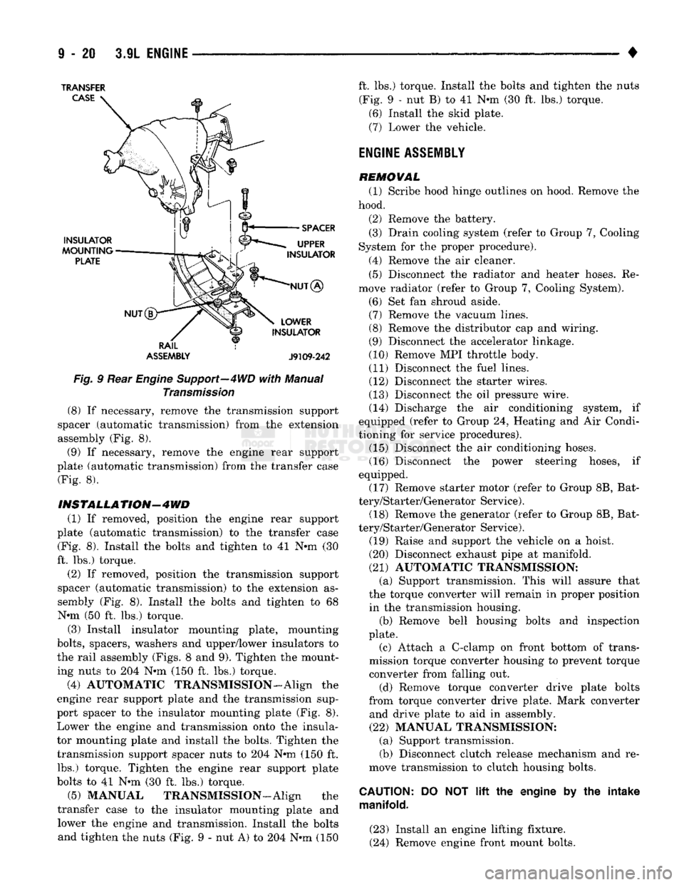
Fig.
9 Rear
Engine
Support—4WD
with
Manual
Transmission
(8) If necessary, remove the transmission support
spacer (automatic transmission) from the extension
assembly (Fig. 8).
(9) If necessary, remove the engine rear support
plate (automatic transmission) from the transfer case (Fig. 8).
INSTALLATION-4WD
(1) If removed, position the engine rear support
plate (automatic transmission) to the transfer case (Fig. 8). Install the bolts and tighten to 41 N-m (30
ft. lbs.) torque.
(2) If removed, position the transmission support
spacer (automatic transmission) to the extension as
sembly (Fig. 8). Install the bolts and tighten to 68 N-m (50 ft. lbs.) torque.
(3) Install insulator mounting plate, mounting
bolts,
spacers, washers and upper/lower insulators to
the rail assembly (Figs. 8 and 9). Tighten the mount
ing nuts to 204 N*m (150 ft. lbs.) torque.
(4) AUTOMATIC TRANSMISSION-Align the
engine rear support plate and the transmission sup
port spacer to the insulator mounting plate (Fig. 8). Lower the engine and transmission onto the insula
tor mounting plate and install the bolts. Tighten the transmission support spacer nuts to 204 N-m (150 ft. lbs.) torque. Tighten the engine rear support plate
bolts to 41 N-m (30 ft. lbs.) torque.
(5) MANUAL TRANSMISSION—Align the
transfer case to the insulator mounting plate and lower the engine and transmission. Install the bolts and tighten the nuts (Fig. 9 - nut A) to 204 N-m (150 ft. lbs.) torque. Install the bolts and tighten the nuts
(Fig. 9 - nut B) to 41 N-m (30 ft. lbs.) torque. (6) Install the skid plate.
(7) Lower the vehicle.
ENGINE
ASSEMBLY
REMOVAL (1) Scribe hood hinge outlines on hood. Remove the
hood.
(2) Remove the battery. (3) Drain cooling system (refer to Group 7, Cooling
System for the proper procedure).
(4) Remove the air cleaner. (5) Disconnect the radiator and heater hoses. Re
move radiator (refer to Group 7, Cooling System).
(6) Set fan shroud aside. (7) Remove the vacuum lines. (8) Remove the distributor cap and wiring.
(9) Disconnect the accelerator linkage.
(10) Remove MPI throttle body. (11) Disconnect the fuel lines. (12) Disconnect the starter wires.
(13) Disconnect the oil pressure wire. (14) Discharge the air conditioning system, if
equipped (refer to Group 24, Heating and Air Condi
tioning for service procedures). (15) Disconnect the air conditioning hoses.
(16) Disconnect the power steering hoses, if
equipped. (17) Remove starter motor (refer to Group 8B, Bat
tery/Starter/Generator Service). (18) Remove the generator (refer to Group 8B, Bat
tery/Starter/Generator Service).
(19) Raise and support the vehicle on a hoist.
(20) Disconnect exhaust pipe at manifold.
(21) AUTOMATIC TRANSMISSION: (a) Support transmission. This will assure that
the torque converter will remain in proper position in the transmission housing. (b) Remove bell housing bolts and inspection
plate.
(c) Attach a C-clamp on front bottom of trans
mission torque converter housing to prevent torque
converter from falling out.
(d) Remove torque converter drive plate bolts
from torque converter drive plate. Mark converter and drive plate to aid in assembly.
(22) MANUAL TRANSMISSION: (a) Support transmission.
(b) Disconnect clutch release mechanism and re
move transmission to clutch housing bolts.
CAUTION:
DO NOT
lift
the engine by the intake
manifold.
(23) Install an engine lifting fixture.
(24) Remove engine front mount bolts.