1993 CHEVROLET PLYMOUTH ACCLAIM steering wheel
[x] Cancel search: steering wheelPage 86 of 2438

CAUTION: Do not pry on or otherwise damage wear
sleeve on outer C/V joint. (5) Support assembly at C/V joint housings. Re-
move by pulling outward on the inner joint housing. DO NOT PULL ON SHAFT (Figs. 10 and 11).
The driveshaft, when installed, acts as a bolt and
secures the hub/bearing assembly. If the vehicle is to
be supported or moved on its wheels, install a bolt
through the hub to ensure that the hub bearing as-
sembly cannot loosen.
DRIVESHAFT ASSEMBLIES INSTALL
CAUTION: See Wear Sleeve and Seal Lubrication in
Front Suspension and at end of this Group BE-
FORE driveshaft installation.
Fig. 6 Remove Speedometer Pinion Clamp (For Right Driveshaft).
Fig. 7 Remove Ball Joint to Steering Knuckle Clamp Bolt
Fig. 8 Separate Ball Joint from Knuckle
Fig. 9 Separate Outer C/V Joint Shaft from Hub
Fig. 10 Removing Driveshaft Assembly UnequalLength
2 - 28 SUSPENSION AND DRIVESHAFTS Ä
Page 151 of 2438

BRAKES
CONTENTS
page page
ANTI-LOCK BRAKE SYSTEMÐBENDIX ANTI-LOCK 10 AC/Y BODY ............. 72
ANTI-LOCK BRAKE SYSTEMÐBENDIX ANTI-LOCK 6 AA,AG,AJ,AP BODY ....... 113
BRAKE DISC (ROTOR) ................... 53
BRAKE SUPPORT ASSEMBLY ............. 25
FRONT DISC BRAKES ................... 31
GENERAL INFORMATION .................. 1
HYDRAULIC SYSTEM CONTROL VALVES . . . 26
KELSEY HAYES DOUBLE PIN FAMILY CALIPER ............................ 35 KELSEY HAYES DOUBLE PIN NON-FAMILY
CALIPER ............................ 38
MASTER CYLINDER ..................... 66
PARKING BRAKES ...................... 57
POWER BRAKES ....................... 68
REAR DISC BRAKES .................... 45
REAR WHEEL DRUM BRAKES ............ 18
SERVICE ADJUSTMENTS .................. 4
WHEEL BEARINGS ...................... 70
WHEEL CYLINDERS ..................... 23
GENERAL INFORMATION
Throughout this group, references may be made to
a particular vehicle by letter or number designation.
A chart showing the break down of these designa-
tions is included in the Introduction Section at the
front of this service manual. Standard brake equipment consists of:
² Double pin floating caliper disc front brakes.
² Rear automatic adjusting drum brakes.
² Differential valve with a brake warning switch.
² Master cylinder.
² Vacuum power booster.
² Double pin floating caliper rear disc brakes are
available on some models. The Bendix Anti-Lock 10 braking system, uses the
standard power brake system caliper assemblies,
braking discs, pedal assembly, brake lines and hoses.
The unique parts of the Bendix Anti-Lock 10 braking
system consists of the following components. Propor-
tioning valves, wheel speed sensors, tone wheels,
electronic control unit, modulator assembly and hy-
draulic assembly. These components replace the con-
ventional master cylinder and power booster. The
components will be described in detail in the Bendix
Anti-Lock 10 brake section in this group of the ser-
vice manual. The Bendix Anti-Lock 6 braking system, uses the
following standard brake system components. Master
cylinder, power booster, caliper assemblies, braking
discs, pedal assembly, brake lines and hoses. The
unique parts of the Bendix Anti-Lock 6 braking sys-
tem consists of the following components. Modulator
assembly, unique proportioning valves, wheel speed
sensors, tone wheels, and electronic control unit.
These components will be described in detail in the
Bendix Anti-Lock 6 brake section in this group of the
service manual. The front disc brake shoes have semi-metallic lin-
ings. The hydraulic brake system (Fig .123and4)is
diagonally split on both the Non-ABS and ABS brak-
ing system. With the left front and right rear brakes
on one hydraulic system and the right front and left
rear on the other. The Non-ABS and ABS brake system may use dif-
ferent types of brake line fittings and tubing flares.
The Non-ABS brake system uses double wall tubing
flares and fittings at all tubing joint locations. Some
ABS brake systems use both ISO style tubing flares
and double wall tubing flares and corresponding fit-
tings at different joint locations. See (Figs . 2 3 and 4)
for specific joint locations and type of tubing flare. The front disc brakes consist of two different types
of caliper assemblies. A double pin Kelsey-Hayes cal-
iper (family caliper) with a bolt-on adapter attached
to the steering knuckle. Or a double pin Kelsey-
Hayes caliper (non-family caliper) which mounts di-
rectly to rails on the steering knuckle. The non-
family caliper is only used on the AY Body
(Imperials).
CAUTION: Caliper pistons, boots and seals for the
different caliper assemblies used on the front and
rear disc brake assemblies are not interchangeable.
Misusage could result in a complete brake system
failure. Be sure that the parts are replaced with the
correct replacement parts, refer to the parts book
for the type and model year of the vehicle being
worked on.
The master cylinder is anodized, lightweight alu-
minum, with a bore size of 24.0mm, 21.0mm or 7/8
inch.
Ä BRAKES 5 - 1
Page 188 of 2438
KELSEY HAYES DOUBLE PIN NON-FAMILY CALIPER INDEX
page page
Assembling Disc Brake Caliper .............. 42
Cleaning and Inspection of Brake Caliper ...... 41 Disc Brake Caliper Disassembly
............. 40
Service Procedures ....................... 38
SERVICE PROCEDURES
BRAKE SHOES REMOVE
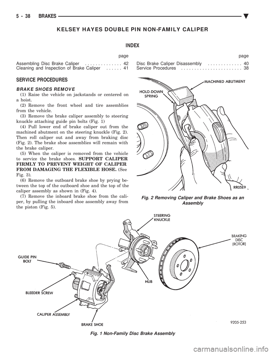
(1) Raise the vehicle on jackstands or centered on
a hoist. (2) Remove the front wheel and tire assemblies
from the vehicle. (3) Remove the brake caliper assembly to steering
knuckle attaching guide pin bolts (Fig. 1) (4) Pull lower end of brake caliper out from the
machined abutment on the steering knuckle (Fig. 2).
Then roll caliper out and away from braking disc
(Fig. 2). The brake shoe assemblies will remain with
the brake caliper. (5) When the caliper is removed from the vehicle
to service the brake shoes. SUPPORT CALIPER
FIRMLY TO PREVENT WEIGHT OF CALIPER
FROM DAMAGING THE FLEXIBLE HOSE. (See
Fig. 3). (6) Remove the outboard brake shoe by prying be-
tween the top of the outboard shoe and the top of the
caliper assembly as shown in (Fig. 4). (7) Remove the inboard brake shoe from the cali-
per, by pulling the inboard shoe assembly away from
the piston (Fig. 5).
Fig. 1 Non-Family Disc Brake Assembly
Fig. 2 Removing Caliper and Brake Shoes as an Assembly
5 - 38 BRAKES Ä
Page 190 of 2438
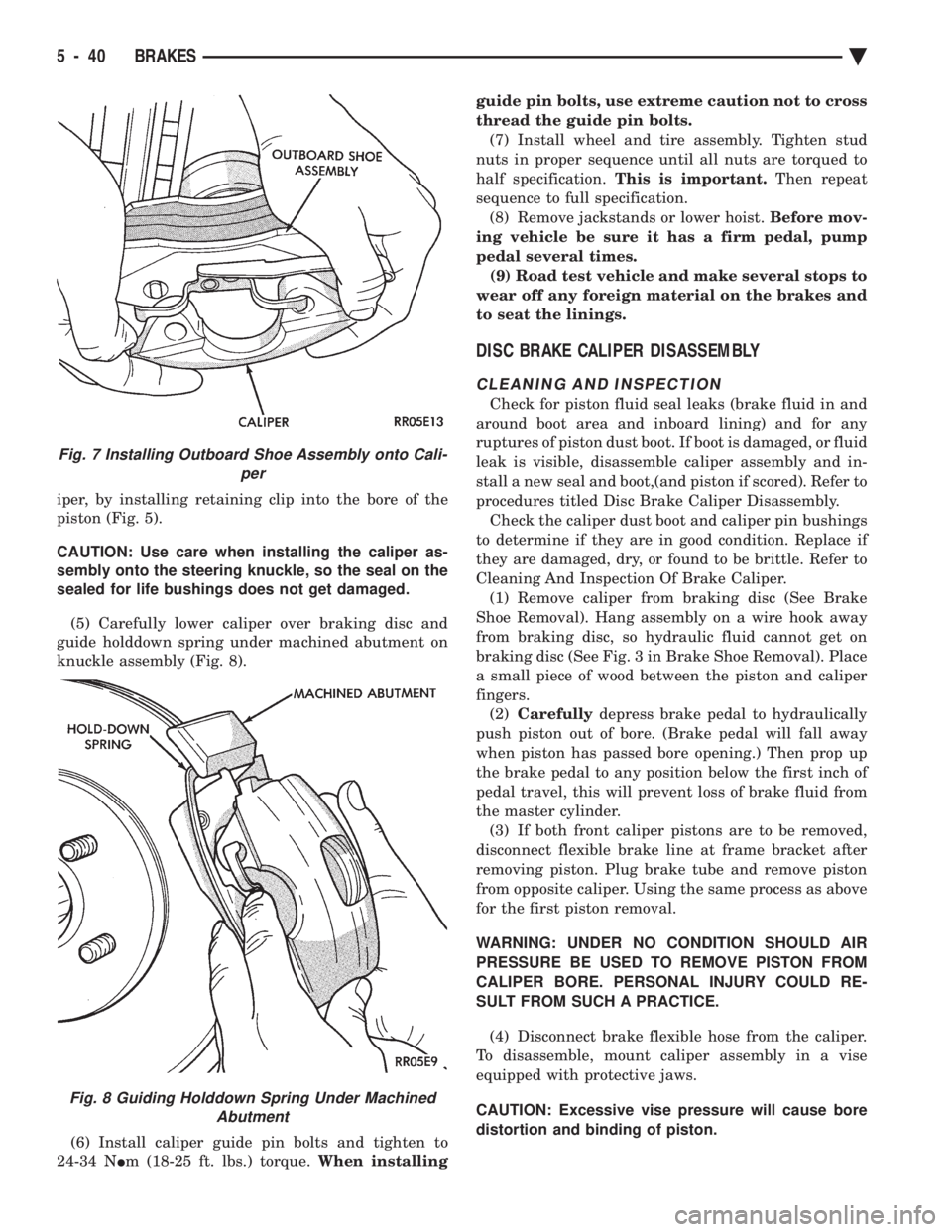
iper, by installing retaining clip into the bore of the
piston (Fig. 5).
CAUTION: Use care when installing the caliper as-
sembly onto the steering knuckle, so the seal on the
sealed for life bushings does not get damaged.
(5) Carefully lower caliper over braking disc and
guide holddown spring under machined abutment on
knuckle assembly (Fig. 8).
(6) Install caliper guide pin bolts and tighten to
24-34 N Im (18-25 ft. lbs.) torque. When installing guide pin bolts, use extreme caution not to cross
thread the guide pin bolts.
(7) Install wheel and tire assembly. Tighten stud
nuts in proper sequence until all nuts are torqued to
half specification. This is important. Then repeat
sequence to full specification. (8) Remove jackstands or lower hoist. Before mov-
ing vehicle be sure it has a firm pedal, pump
pedal several times. (9) Road test vehicle and make several stops to
wear off any foreign material on the brakes and
to seat the linings.
DISC BRAKE CALIPER DISASSEMBLY
CLEANING AND INSPECTION
Check for piston fluid seal leaks (brake fluid in and
around boot area and inboard lining) and for any
ruptures of piston dust boot. If boot is damaged, or fluid
leak is visible, disassemble caliper assembly and in-
stall a new seal and boot,(and piston if scored). Refer to
procedures titled Disc Brake Caliper Disassembly. Check the caliper dust boot and caliper pin bushings
to determine if they are in good condition. Replace if
they are damaged, dry, or found to be brittle. Refer to
Cleaning And Inspection Of Brake Caliper. (1) Remove caliper from braking disc (See Brake
Shoe Removal). Hang assembly on a wire hook away
from braking disc, so hydraulic fluid cannot get on
braking disc (See Fig. 3 in Brake Shoe Removal). Place
a small piece of wood between the piston and caliper
fingers. (2) Carefully depress brake pedal to hydraulically
push piston out of bore. (Brake pedal will fall away
when piston has passed bore opening.) Then prop up
the brake pedal to any position below the first inch of
pedal travel, this will prevent loss of brake fluid from
the master cylinder. (3) If both front caliper pistons are to be removed,
disconnect flexible brake line at frame bracket after
removing piston. Plug brake tube and remove piston
from opposite caliper. Using the same process as above
for the first piston removal.
WARNING: UNDER NO CONDITION SHOULD AIR
PRESSURE BE USED TO REMOVE PISTON FROM
CALIPER BORE. PERSONAL INJURY COULD RE-
SULT FROM SUCH A PRACTICE.
(4) Disconnect brake flexible hose from the caliper.
To disassemble, mount caliper assembly in a vise
equipped with protective jaws.
CAUTION: Excessive vise pressure will cause bore
distortion and binding of piston.
Fig. 7 Installing Outboard Shoe Assembly onto Cali- per
Fig. 8 Guiding Holddown Spring Under MachinedAbutment
5 - 40 BRAKES Ä
Page 203 of 2438
BRAKE DISC (ROTOR) INDEX
page page
Braking Disc Removal ..................... 54
General Information ....................... 53
Inspection Diagnosis ...................... 53 Installing Braking Disc
..................... 54
Refinishing Braking Disc ................... 55
Service Procedures ....................... 53
GENERAL INFORMATION
Any servicing of the braking disc requires extreme
care to maintain the braking disc within service toler-
ances to ensure proper brake action.
CAUTION: If the braking disk (rotor) needs to be
replaced with a new part. The protective coating on
the braking surfaces of the rotor MUST BE REMOVED
with an appropriate solvent, to avoid contamination
of the brake shoe linings.
When replacing a rotor with a new part do NOT
reface the new rotor. Rotor already has the re-
quired micro finish when manufactured, only
remove the protective coating.
INSPECTION DIAGNOSIS
Before refinishing or refacing a braking disc, the disc
should be checked and inspected for the following
conditions: Braking surface scoring, rust, impregnation of lining
material and worn ridges. Excessive lateral rotor runout or wobble.
Thickness variation (Parallelism).
Dishing or distortion (Flatness).
If a vehicle has not been driven for a period of time.
The discs will rust in the area not covered by the brake
lining and cause noise and chatter when the brakes are
applied. Excessive wear and scoring of the disc can cause
temporary improper lining contact if ridges are not
removed before installation of new brake shoe assem-
blies. Some discoloration or wear of the disc surface is
normal and does not require resurfacing when linings
are replaced. Excessive runout or wobble in a disc can increase
pedal travel due to piston knock back. This will in-
crease guide pin bushing wear due to tendency of
caliper to follow disc wobble. Thickness variation in a disc can also result in pedal
pulsation, chatter and surge due to variation in brake
output. This can also be caused by excessive runout in
braking disc or hub. Dishing or distortion can be caused by extreme heat
and abuse of the brakes.
SERVICE PROCEDURES
CHECKING BRAKING DISC FOR RUNOUT AND THICKNESS
On vehicle, braking disc (rotor) runout is the com-
bination of the individual runout of the hub face and
the runout of the disc. (The hub and disc are separa-
ble). To measure runout on the vehicle, remove the
wheel and reinstall the lug nuts tightening the disc
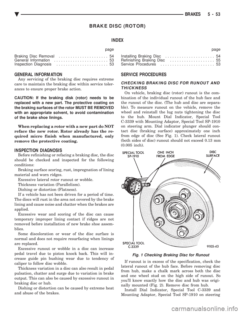
to the hub. Mount Dial Indicator, Special Tool
C-3339 with Mounting Adaptor, Special Tool SP-1910
on steering arm. Dial indicator plunger should con-
tact disc (braking surface) approximately one inch
from edge of disc (See Fig. 1). Check lateral runout
(both sides of disc) runout should not exceed 0.13 mm
(0.005 inch).
If runout is in excess of the specification, check the
lateral runout of the hub face. Before removing disc
from hub, make a chalk mark across both the disc
and one wheel stud on the high side of runout. So
you'll know exactly how the disc and hub was origi-
nally mounted (Fig. 2). Remove disc from hub. Install Dial Indicator, Special Tool C-3339 and
Mounting Adaptor, Special Tool SP-1910 on steering
Fig. 1 Checking Braking Disc for Runout
Ä BRAKES 5 - 53
Page 222 of 2438
ANTI-LOCK BRAKE SYSTEMÐBENDIX ANTI-LOCK 10 AC/Y BODY INDEX
page page
ABS Brake System Diagnostic Features ....... 92
ABS Braking System Diagnosis .............. 87
ABS Controller Anti-Lock Brake (CAB) Service Precautions ........................... 88
ABS Equipped Vehicle Performance .......... 75
ABS Hydraulic Circuits and Valve Operation .... 85
ABS System Diagnostic Connector ........... 82
ABS System General Service Precautions ...... 88
ABS System Self-Diagnostics ............... 75
ABS Warning Systems Operation ............ 75
Anti-Lock Brake System Components ......... 76 Anti-Lock Brake System Definitions
........... 72
Anti-Lock Operation and Performance ......... 73
Anti-Lock System Relays and Warning Lamps . . . 82
Controller Anti-Lock Brake (CAB) ............. 80
Electronic Components ................... 103
General Information ....................... 72
General Service Precautions ................ 93
Major ABS Components ................... 73
Mechanical Diagnostics and Service Procedures . 89
Normal Braking System Function ............. 72
On Car Hydraulic ABS Component Service ..... 93
GENERAL INFORMATION
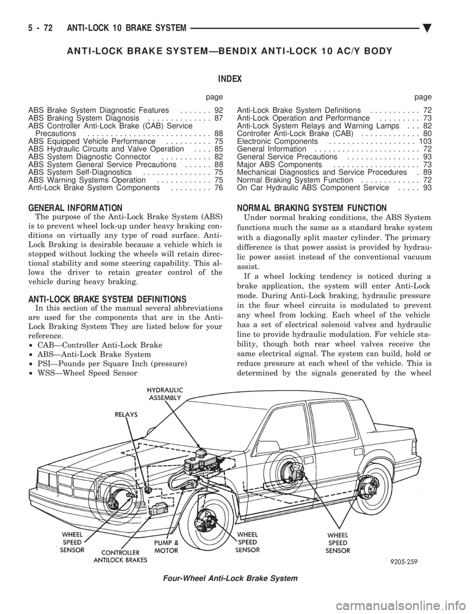
The purpose of the Anti-Lock Brake System (ABS)
is to prevent wheel lock-up under heavy braking con-
ditions on virtually any type of road surface. Anti-
Lock Braking is desirable because a vehicle which is
stopped without locking the wheels will retain direc-
tional stability and some steering capability. This al-
lows the driver to retain greater control of the
vehicle during heavy braking.
ANTI-LOCK BRAKE SYSTEM DEFINITIONS
In this section of the manual several abbreviations
are used for the components that are in the Anti-
Lock Braking System They are listed below for your
reference.
² CABÐController Anti-Lock Brake
² ABSÐAnti-Lock Brake System
² PSIÐPounds per Square Inch (pressure)
² WSSÐWheel Speed Sensor
NORMAL BRAKING SYSTEM FUNCTION
Under normal braking conditions, the ABS System
functions much the same as a standard brake system
with a diagonally split master cylinder. The primary
difference is that power assist is provided by hydrau-
lic power assist instead of the conventional vacuum
assist. If a wheel locking tendency is noticed during a
brake application, the system will enter Anti-Lock
mode. During Anti-Lock braking, hydraulic pressure
in the four wheel circuits is modulated to prevent
any wheel from locking. Each wheel of the vehicle
has a set of electrical solenoid valves and hydraulic
line to provide hydraulic modulation. For vehicle sta-
bility, though both rear wheel valves receive the
same electrical signal. The system can build, hold or
reduce pressure at each wheel of the vehicle. This is
determined by the signals generated by the wheel
Four-Wheel Anti-Lock Brake System
5 - 72 ANTI-LOCK 10 BRAKE SYSTEM Ä
Page 229 of 2438
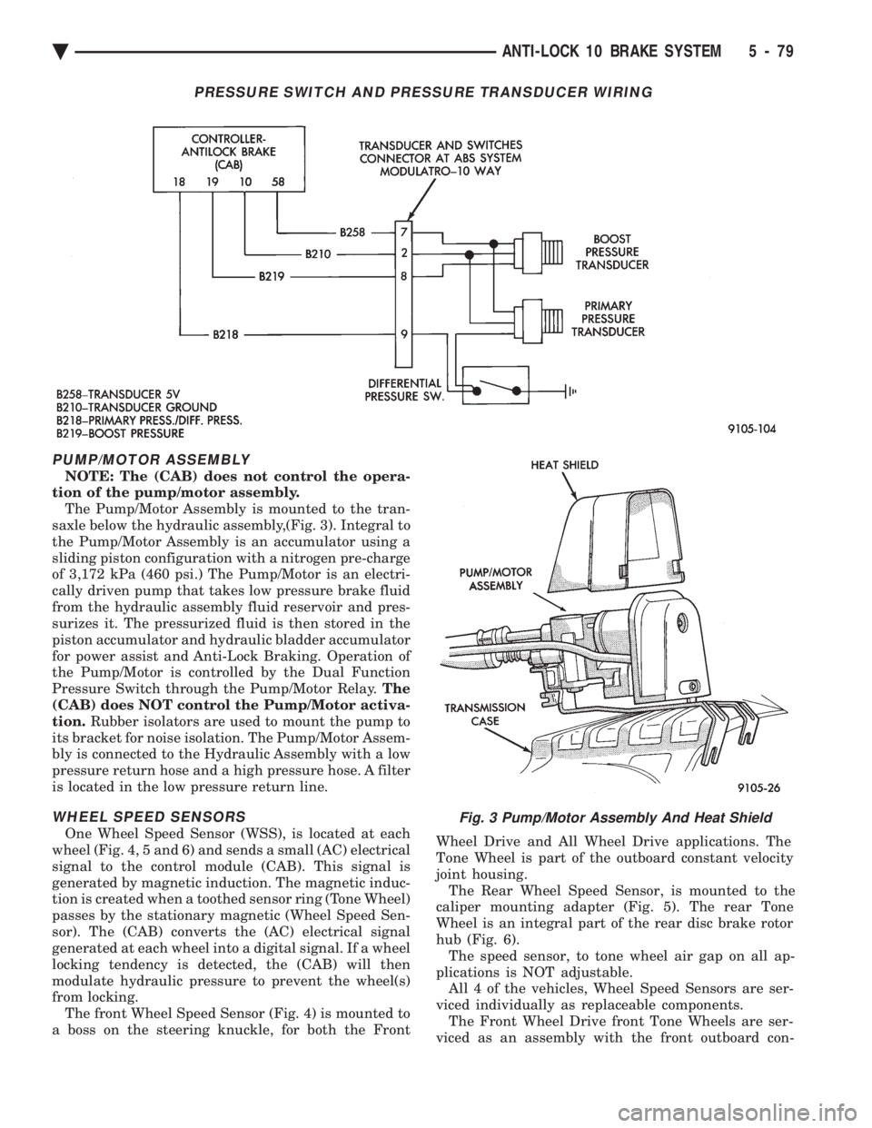
PUMP/MOTOR ASSEMBLY
NOTE: The (CAB) does not control the opera-
tion of the pump/motor assembly. The Pump/Motor Assembly is mounted to the tran-
saxle below the hydraulic assembly,(Fig. 3). Integral to
the Pump/Motor Assembly is an accumulator using a
sliding piston configuration with a nitrogen pre-charge
of 3,172 kPa (460 psi.) The Pump/Motor is an electri-
cally driven pump that takes low pressure brake fluid
from the hydraulic assembly fluid reservoir and pres-
surizes it. The pressurized fluid is then stored in the
piston accumulator and hydraulic bladder accumulator
for power assist and Anti-Lock Braking. Operation of
the Pump/Motor is controlled by the Dual Function
Pressure Switch through the Pump/Motor Relay. The
(CAB) does NOT control the Pump/Motor activa-
tion. Rubber isolators are used to mount the pump to
its bracket for noise isolation. The Pump/Motor Assem-
bly is connected to the Hydraulic Assembly with a low
pressure return hose and a high pressure hose. A filter
is located in the low pressure return line.
WHEEL SPEED SENSORS
One Wheel Speed Sensor (WSS), is located at each
wheel (Fig. 4, 5 and 6) and sends a small (AC) electrical
signal to the control module (CAB). This signal is
generated by magnetic induction. The magnetic induc-
tion is created when a toothed sensor ring (Tone Wheel)
passes by the stationary magnetic (Wheel Speed Sen-
sor). The (CAB) converts the (AC) electrical signal
generated at each wheel into a digital signal. If a wheel
locking tendency is detected, the (CAB) will then
modulate hydraulic pressure to prevent the wheel(s)
from locking. The front Wheel Speed Sensor (Fig. 4) is mounted to
a boss on the steering knuckle, for both the Front Wheel Drive and All Wheel Drive applications. The
Tone Wheel is part of the outboard constant velocity
joint housing. The Rear Wheel Speed Sensor, is mounted to the
caliper mounting adapter (Fig. 5). The rear Tone
Wheel is an integral part of the rear disc brake rotor
hub (Fig. 6). The speed sensor, to tone wheel air gap on all ap-
plications is NOT adjustable. All 4 of the vehicles, Wheel Speed Sensors are ser-
viced individually as replaceable components. The Front Wheel Drive front Tone Wheels are ser-
viced as an assembly with the front outboard con-
Fig. 3 Pump/Motor Assembly And Heat Shield
PRESSURE SWITCH AND PRESSURE TRANSDUCER WIRING
Ä ANTI-LOCK 10 BRAKE SYSTEM 5 - 79
Page 232 of 2438

The primary functions of the (CAB) are:
² (1) Detect wheel locking tendencies.
² (2) Control fluid modulation to the brakes while in
Anti-Lock mode.
² (3) Monitor the system for proper operation.
² (4) Provide communication to the DRB II while in
diagnostic mode. The (CAB) continuously monitors the speed of each
wheel, through the signals generated at the Wheel
Speed Sensors, to determine if any wheel is begin-
ning to lock. When a wheel locking tendency is de-
tected, the (CAB) will isolate the master cylinder
from the wheel brakes. This is done by activating the
Isolation Valves. The (CAB) then commands the ap-
propriate Build or Decay valves to modulate brake
fluid pressure in some or all of the hydraulic circuits.
The fluid used for modulation comes from the booster
servo circuit. The (CAB) continues to control pres-
sure in individual hydraulic circuits until a locking
tendency is no longer present. The (ABS) system is constantly monitored by the
(CAB) for proper operation. If the (CAB) detects a
fault, it can disable the Anti-Lock braking function.
Depending on the fault, the (CAB) will light one or
both of the brake warning lamps. The (CAB) contains a System Diagnostic Program
which triggers the brake system warning lamps
when a system fault is detected. Faults are stored in
a diagnostic program memory. There are 19 fault
codes that may be stored in the (CAB) and displayed
through the DRB II. These fault codes will remain in
the (CAB) memory even after the ignition has been
turned off. These fault codes will remain in memory
until they are cleared with the DRB II, or automati-
cally erased from the memory after (50) ignition
switch on/off cycles.
CONTROLLER ANTI-LOCK BRAKE (INPUTS)
² Four wheel speed sensors.
² Boost pressure transducer.
² Primary pressure transducer.
² Low fluid level switch.
² Differential pressure switch.
² Parking brake switch.
² Dual function pressure switch (warning pressure
only)
² Stop lamp switch.
² Ignition switch.
² System relay voltage.
² Ground.
² Low Accumulator
CONTROLLER ANTI-LOCK BRAKE (OUTPUTS)
²Ten modulator valves-3 decay, 3 build and 4 isola-
tion.
² Red Brake warning lamp.
² Amber Anti-Lock Warning Lamp.
² System relay actuation. ²
Diagnostic communication.
ABS SYSTEM DIAGNOSTIC CONNECTOR
The Bendix Anti-Lock system diagnostic connector
is located under the lower dash panel or in the area
of the fuse box (Fig. 8). The fuse box is located be-
hind the access panel that is on the bottom portion of
the dash panel, left of the steering column. The diag-
nostics connector is a blue 6 way connector.
ANTI-LOCK SYSTEM RELAYS AND WARNING
LAMPS
PUMP/MOTOR RELAY
Pump/Motor power is supplied by the Pump/Motor
Relay. The Pump/Motor relay is located inside the
Power Distribution Center (PDC). The relay coil is
energized by a ground from the Dual Function Pres-
sure Switch. See (Fig. 9) for the location of the pump/
motor relay in the (PDC).
SYSTEM RELAY
The (ABS) Modulator Valves and Anti-Lock Warn-
ing Lamp Relay are controlled through a System Re-
lay. The System relay is located on the top left inner
fender behind the headlight (Fig. 10). The system re-
lay provides power to the (CAB) for modulator valve
operation (pins 47 and 50) after the start-up cycle
when the ignition is turned on.
ANTI-LOCK WARNING LAMP RELAY
The Anti-Lock Warning Lamp is controlled by the
Yellow Light Relay. See (Fig. 10) for location behind
the left headlight. With the relay de-energized, the
lamp is lit. When the system relay is energized by
Fig. 8 A.B.S. Diagnostic Connector Location
5 - 82 ANTI-LOCK 10 BRAKE SYSTEM Ä