1993 CHEVROLET PLYMOUTH ACCLAIM transmission oil
[x] Cancel search: transmission oilPage 53 of 2438
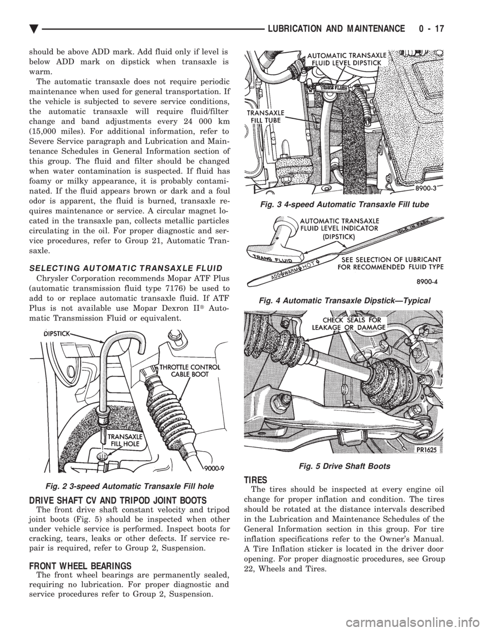
should be above ADD mark. Add fluid only if level is
below ADD mark on dipstick when transaxle is
warm.The automatic transaxle does not require periodic
maintenance when used for general transportation. If
the vehicle is subjected to severe service conditions,
the automatic transaxle will require fluid/filter
change and band adjustments every 24 000 km
(15,000 miles). For additional information, refer to
Severe Service paragraph and Lubrication and Main-
tenance Schedules in General Information section of
this group. The fluid and filter should be changed
when water contamination is suspected. If fluid has
foamy or milky appearance, it is probably contami-
nated. If the fluid appears brown or dark and a foul
odor is apparent, the fluid is burned, transaxle re-
quires maintenance or service. A circular magnet lo-
cated in the transaxle pan, collects metallic particles
circulating in the oil. For proper diagnostic and ser-
vice procedures, refer to Group 21, Automatic Tran-
saxle.
SELECTING AUTOMATIC TRANSAXLE FLUID
Chrysler Corporation recommends Mopar ATF Plus
(automatic transmission fluid type 7176) be used to
add to or replace automatic transaxle fluid. If ATF
Plus is not available use Mopar Dexron II tAuto-
matic Transmission Fluid or equivalent.
DRIVE SHAFT CV AND TRIPOD JOINT BOOTS
The front drive shaft constant velocity and tripod
joint boots (Fig. 5) should be inspected when other
under vehicle service is performed. Inspect boots for
cracking, tears, leaks or other defects. If service re-
pair is required, refer to Group 2, Suspension.
FRONT WHEEL BEARINGS
The front wheel bearings are permanently sealed,
requiring no lubrication. For proper diagnostic and
service procedures refer to Group 2, Suspension.
TIRES
The tires should be inspected at every engine oil
change for proper inflation and condition. The tires
should be rotated at the distance intervals described
in the Lubrication and Maintenance Schedules of the
General Information section in this group. For tire
inflation specifications refer to the Owner's Manual.
A Tire Inflation sticker is located in the driver door
opening. For proper diagnostic procedures, see Group
22, Wheels and Tires.Fig. 2 3-speed Automatic Transaxle Fill hole
Fig. 3 4-speed Automatic Transaxle Fill tube
Fig. 4 Automatic Transaxle DipstickÐTypical
Fig. 5 Drive Shaft Boots
Ä LUBRICATION AND MAINTENANCE 0 - 17
Page 253 of 2438
ELECTRONIC COMPONENTS
CONTROLLER ANTI-LOCK BRAKE (CAB)
REMOVAL (1) Turn vehicle ignition off.
(2) Raise vehicle on hoist, (CAB) access for re-
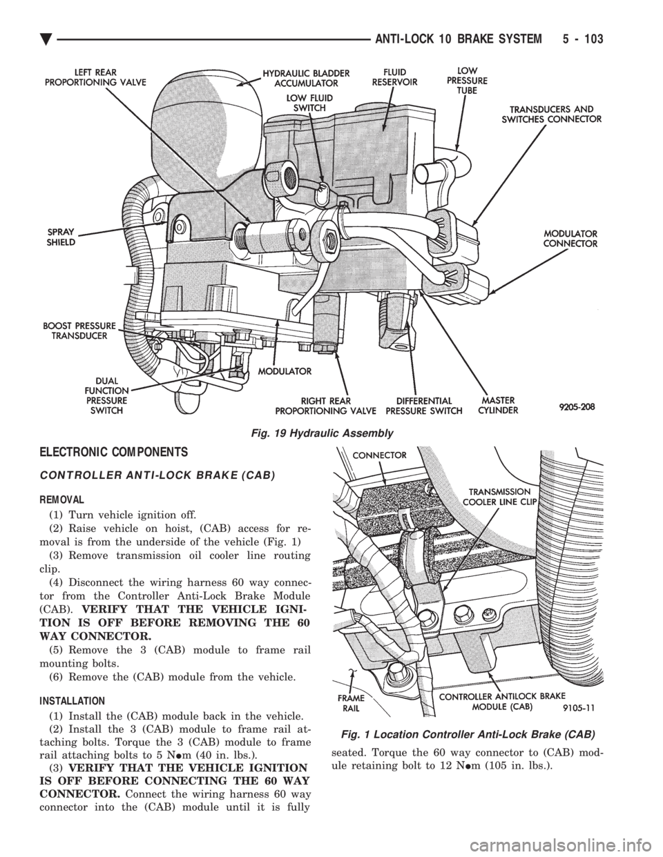
moval is from the underside of the vehicle (Fig. 1) (3) Remove transmission oil cooler line routing
clip. (4) Disconnect the wiring harness 60 way connec-
tor from the Controller Anti-Lock Brake Module
(CAB). VERIFY THAT THE VEHICLE IGNI-
TION IS OFF BEFORE REMOVING THE 60
WAY CONNECTOR. (5) Remove the 3 (CAB) module to frame rail
mounting bolts. (6) Remove the (CAB) module from the vehicle.
INSTALLATION (1) Install the (CAB) module back in the vehicle.
(2) Install the 3 (CAB) module to frame rail at-
taching bolts. Torque the 3 (CAB) module to frame
rail attaching bolts to 5 N Im (40 in. lbs.).
(3) VERIFY THAT THE VEHICLE IGNITION
IS OFF BEFORE CONNECTING THE 60 WAY
CONNECTOR. Connect the wiring harness 60 way
connector into the (CAB) module until it is fully seated. Torque the 60 way connector to (CAB) mod-
ule retaining bolt to 12 N Im (105 in. lbs.).
Fig. 19 Hydraulic Assembly
Fig. 1 Location Controller Anti-Lock Brake (CAB)
Ä ANTI-LOCK 10 BRAKE SYSTEM 5 - 103
Page 333 of 2438

MANUAL TRANSAXLE CLUTCH
CONTENTS
page page
CLEANING PRECAUTIONS ................. 6
CLUTCH CABLE MECHANISM .............. 1
CLUTCH CABLE REPLACEMENT ............ 2
CLUTCH CHATTER COMPLAINTS ........... 1
CLUTCH DISC REPLACEMENT ............. 5
CLUTCH PEDAL NOISE/POP ............... 2 CLUTCH PEDAL POSITION SWITCH
......... 4
EXCESSIVE CLUTCH SPIN TIME/CLASH INTO REVERSE COMPLAINTS ............ 1
GENERAL INFORMATION .................. 1
RELEASE BEARING AND FORK ............. 6
GENERAL INFORMATION
Throughout this group, references may be made to
a particular vehicle by letter or number designation.
A chart showing the breakdown of these designations
is included in the Introduction Section at the front of
this service manual. The clutch used in all models are a single, dry disc
type with no adjustment for wear being provided in
the clutch itself. The clutch pedal is connected to the release shaft
through a cable and lever. The upper end of the clutch pedal pivots in the
pedal bracket on two nylon bushings. These bushings
do not require periodic lubrication.
CLUTCH CHATTER COMPLAINTS
For all clutch chatter complaints, do the following:
(1) Check for loose, misaligned, or broken engine
and transmission mounts. If present, they should be
corrected at this time. Test vehicle for chatter. If
chatter is gone, there is no need to go any further. If
chatter persists: (2) Check to see if clutch cable routing is correct
and operates smoothly. (3) Check for loose connections in drive train. Cor-
rect any problems and determine if clutch chatter
complaints has been satisfied. If not, (4) Remove transaxle. See Group 21, Manual Tran-
saxle, for procedure. (5) Check to see if the release bearing is sticky or
binding. Replace bearing, if needed. (6) Check linkage for excessive wear on bushings.
Replace all worn parts. A small amount of bearing
grease between the release shaft bushings and the
shaft is beneficial, but not required. (7) Check flywheel and clutch pressure plate for
contamination (dirt, oil) or scored. Replace flywheel
and/or pressure plate, if required. (8) Check to see if the clutch disc hub splines are
damaged. Replace with new disc. (9) Check input shaft splines for damage. Replace
if necessary. (10) Check for uneven wear on clutch fingers.
EXCESSIVE CLUTCH SPIN TIME/CLASH INTO
REVERSE COMPLAINTS
For all excessive clutch spin time/clash into reverse
complaints, do the following: (1) Depress clutch pedal to floor and hold. After
three seconds, shift to reverse. If clash is present,
clutch has excessive spin time. (2) Remove transaxle. See Group 21, Manual Tran-
saxle, for procedure. (3) Check the input shaft spline, clutch disc splines
and release bearing for dry rust. If present, clean
rust off and apply a light coat of bearing grease to
the input shaft splines. Apply grease on the input
shaft splines only where the clutch disc slides. (4) Check to see if the clutch disc hub splines are
damaged, replace with new disc if required. (5) Check the input shaft for damaged splines. Re-
place as necessary. (6) Check for excessive clutch disc runout or
warpage. (7) Install clutch assembly and transaxle.
CLUTCH CABLE MECHANISM
The manual transaxle clutch release system has a
unique self-adjusting mechanism to compensate for
clutch disc wear. This adjuster mechanism is located
within the clutch pedal. The preload spring main-
tains tension on the cable. This tension keeps the
clutch release bearing continuously loaded against
the fingers of the clutch cover assembly. When the pedal is depressed, teeth on the adjuster
and the positioner engage and pull the release cable.
A spring located behind the adjuster ensures proper
tooth engagement. When the pedal is released, the adjuster contacts
the bumper. This separates the adjuster and posi-
tioner teeth, allowing the preload spring to function.
Ä MANUAL TRANSAXLE CLUTCH 6 - 1
Page 343 of 2438
COOLING SYSTEM
CONTENTS
page page
ACCESSORY DRIVE BELTS ............... 24
ENGINE BLOCK HEATER ................. 28
GENERAL INFORMATION .................. 1 SERVICE PROCEDURES
.................. 10
SPECIFICATIONS ....................... 29
GENERAL INFORMATION
Throughout this group, references may be made to
a particular vehicle by letter or number designation.
A chart showing the breakdown of these designations
is included in the Introduction Section at the front of
this service manual.
COOLING SYSTEM
The cooling system consists of an engine cooling
module, thermostat, coolant, a water pump to circu-
late the coolant. The engine cooling module may con-
sist of a radiator, electric fan motor, shroud, radiator
pressure cap, coolant reserve system, transmission oil
cooler, hoses, clamps, air condition condenser, trans-
mission oil lines and charge air cooler.
² When Engine is cold: Thermostat is closed, cooling
system has no flow through the radiator. The coolant
bypass flows through the engine only. ²
When Engine is warm: Thermostat is open, cooling
system has bypass flow and coolant flow through ra-
diator. Its primary purpose is to maintain engine temper-
ature in a range that will provide satisfactory engine
performance and emission levels under all expected
driving conditions. It also provides hot water (cool-
ant) for heater performance and cooling for auto-
matic transmission oil. It does this by transferring
heat from engine metal to coolant, moving this
heated coolant to the radiator, and then transferring
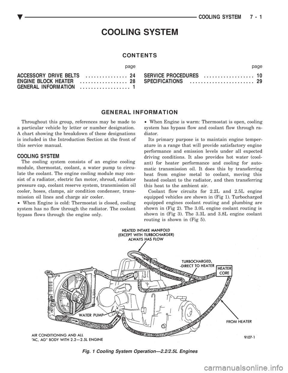
this heat to the ambient air. Coolant flow circuits for 2.2L and 2.5L engine
equipped vehicles are shown in (Fig 1). Turbocharged
equipped engines coolant routing and plumbing are
shown in (Fig 2). The 3.0L engine coolant routing is
shown in (Fig 3). The 3.3L and 3.8L engine coolant
routing is shown in (Fig 5).
Fig. 1 Cooling System OperationÐ2.2/2.5L Engines
Ä COOLING SYSTEM 7 - 1
Page 352 of 2438
SERVICE PROCEDURES INDEX
page page
Automatic Transmission Oil Coolers .......... 23
Coolant ................................ 14
Coolant Recovery System (CRS) ............. 17
Cooling System Drain, Clean, Flush and Refill . . 15
Electric Fan Motor ........................ 22
Engine Thermostats ....................... 13
Fan Shroud ............................. 23 Fans
.................................. 21
Radiator Hoses .......................... 21
Radiator Pressure Cap .................... 18
Radiators ............................... 18
Testing System for Leaks .................. 17
Water Pumps ........................... 10
WATER PUMPS
A quick test to tell whether or not the pump is
working is to see if the heater warms properly. A
defective pump will not be able to circulate heated
coolant through the long heater hose. The water pump on all models can be replaced
without discharging the air conditioning system.
WATER PUMPÐ2.2/2.5L ENGINE
The 2.2/2.5L engine water pump has a diecast alu-
minum body and housing with a stamped steel impel-
ler. The 2.2/2.5L pump uses an O-ring gasket between
body and housing. The assembly bolts directly to the
block. Cylinder block to water pump sealing is provided
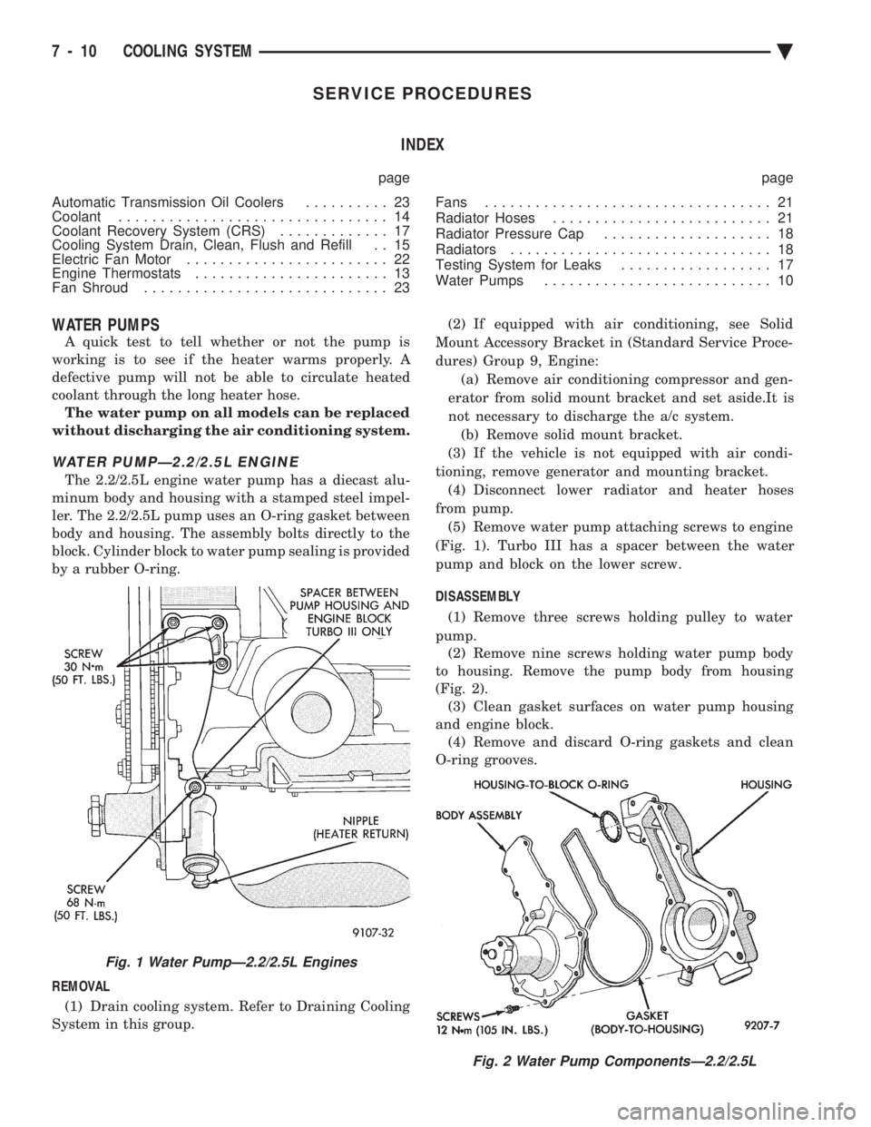
by a rubber O-ring.
REMOVAL (1) Drain cooling system. Refer to Draining Cooling
System in this group. (2) If equipped with air conditioning, see Solid
Mount Accessory Bracket in (Standard Service Proce-
dures) Group 9, Engine: (a) Remove air conditioning compressor and gen-
erator from solid mount bracket and set aside.It is
not necessary to discharge the a/c system. (b) Remove solid mount bracket.
(3) If the vehicle is not equipped with air condi-
tioning, remove generator and mounting bracket. (4) Disconnect lower radiator and heater hoses
from pump. (5) Remove water pump attaching screws to engine
(Fig. 1). Turbo III has a spacer between the water
pump and block on the lower screw.
DISASSEMBLY (1) Remove three screws holding pulley to water
pump. (2) Remove nine screws holding water pump body
to housing. Remove the pump body from housing
(Fig. 2). (3) Clean gasket surfaces on water pump housing
and engine block. (4) Remove and discard O-ring gaskets and clean
O-ring grooves.
Fig. 2 Water Pump ComponentsÐ2.2/2.5L
Fig. 1 Water PumpÐ2.2/2.5L Engines
7 - 10 COOLING SYSTEM Ä
Page 357 of 2438

-37ÉC (-35ÉF) to -59ÉC (-50ÉF). If it looses color or
becomes contaminated, drain, flush, and replace with
fresh properly mixed solution.
SERVICE
Coolant should be changed at 52,500 miles or three
years, whichever occurs first, then every two years or
30,000 miles.
ROUTINE LEVEL CHECK
Do not remove radiator cap for routine coolant
level inspections. The coolant reserve system provides a quick visual
method for determining the coolant level without re-
moving the radiator cap. Simply observe, with the
engine idling and warmed up to normal operating
temperature, that the level of the coolant in the reserve
tank (Figs. 5 and 6) is between the minimum and
maximum marks.
ADDING ADDITIONAL COOLANT
The radiator cap should not be removed. When
additional coolant is needed to maintain this level, it
should be added to the coolant reserve tank. Use only
50/50 concentration of ethylene glycol type antifreeze
and water.
SERVICE COOLANT LEVEL
The cooling system is closed and designed to main-
tain coolant level to the top of the radiator. When servicing requires a coolant level check in the
radiator, the engine must be offand notunder pres-
sure. Drain several ounces of coolant from the radiator
drain cock while observing the Coolant Recovery Sys-
tem (CRS) Tank. Coolant level in the CRS tank should
drop slightly. Then remove the radiator cap. The radia-
tor should be full to the top. If not, and the coolant level
in the CRS tank is at the MIN mark there is a air leak
in the CRS system. Check hose or hose connections to
the CRS tank, radiator filler neck or the pressure cap
seal to the radiator filler neck for leaks.
LOW COOLANT LEVEL AERATION
Low coolant level in a cross flow radiator will equal-
ize in both tanks with engine off. With engine at
running operating temperature the high pressure inlet
tank runs full and the low pressure outlet tank drops.
If this level drops below the top of the transmission oil
cooler, air will be sucked into the water pump:
² Transmission oil will become hotter.
² High reading shown on the temperature gauge.
² Air in the coolant will also cause loss of flow through
the heater.
² Exhaust gas leaks into the coolant can also cause the
same problems.
DEAERATION
Air can only be removed from the system by gather-
ing under the pressure cap. On the next heat up it will
be pushed past the pressure cap into the CRS tank by
thermal expansion of the coolant. It then escapes to the
atmosphere in the CRS tank and is replaced with solid
coolant on cool down.
COOLING SYSTEM DRAIN, CLEAN, FLUSH AND
REFILL
Drain, flush, and fill the cooling system at the
mileage or time intervals specified in the Maintenance
Schedule in this Group. If the solution is dirty or rusty
or contains a considerable amount of sediment, clean
and flush with a reliable cooling system cleaner. Care
should be taken in disposing of the used engine coolant
from your vehicle. Check governmental regulations for
disposal of used engine coolant.
DRAINING
To drain cooling system move temperature selector
for heater to full heat with engine running (to provide
vacuum for actuation). Without removing radiator
pressure cap and with system not under pres-
sure, Shut engine off and open draincock. The coolant
reserve tank (Fig. 5) should empty first, then remove
radiator pressure cap. (if not, see Testing Cooling
System for leaks). To vent 2.2/2.5L engines remove the
plug above thermostat housing (Fig. 1). For Turbo III
engines remove coolant temperature sensor in the
thermostat housing (Fig. 2). For 3.3L /3.8L engine
remove the engine temperature sending unit (Fig. 3).
Removal of a plug or other component is required
because the thermostat has no air vent and prevents
air flow through it. This allows the coolant to drain
from the engine block.
Fig. 1 Thermostat Housing Drain/Fill PlugÐ2.2/2.5L Engines
Ä COOLING SYSTEM 7 - 15
Page 365 of 2438
FAN SHROUD
All vehicles have fan shrouds to improve fan air
flow efficiency. These fan shrouds cover less than full
radiator frontal area to prevent the shroud from re-
stricting air flow at high speeds. The shroud supports the electric fan motor and fan.
For removal and installation see Radiator Section.
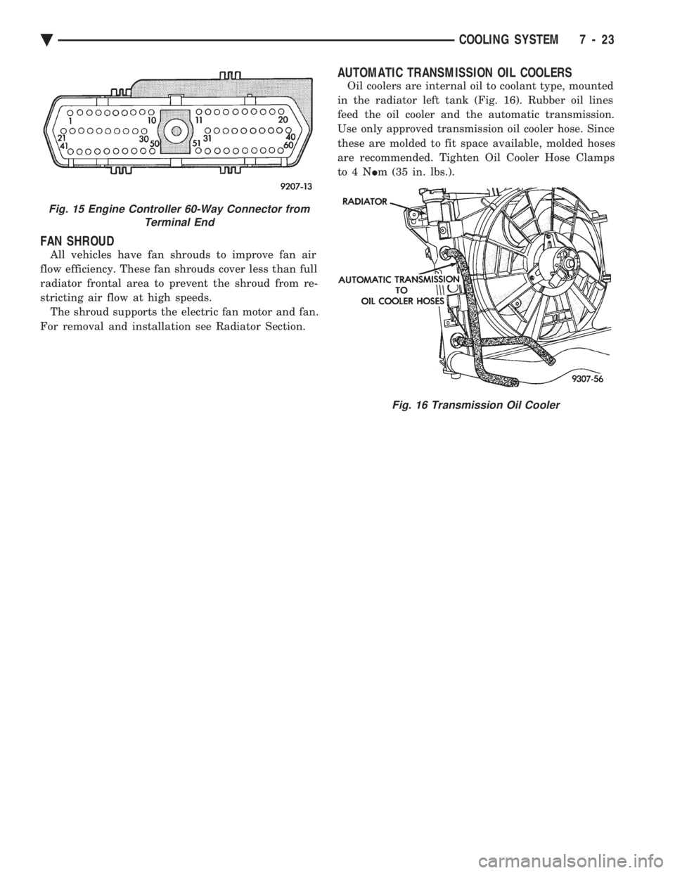
AUTOMATIC TRANSMISSION OIL COOLERS
Oil coolers are internal oil to coolant type, mounted
in the radiator left tank (Fig. 16). Rubber oil lines
feed the oil cooler and the automatic transmission.
Use only approved transmission oil cooler hose. Since
these are molded to fit space available, molded hoses
are recommended. Tighten Oil Cooler Hose Clamps
to4N Im (35 in. lbs.).
Fig. 15 Engine Controller 60-Way Connector from
Terminal End
Fig. 16 Transmission Oil Cooler
Ä COOLING SYSTEM 7 - 23
Page 383 of 2438

STARTER TEST PROCEDURES ON VEHICLE INDEX
page page
Diagnostic Preparation ..................... 11
General Information ....................... 11 Starter Control Circuit Tests
................ 15
Starter Feed Circuit Tests .................. 11
GENERAL INFORMATION
The starting system (Fig. 1) has:
² Ignition switch
² Starter relay (Fig. 2)
² Neutral starting and back-up switch with auto-
matic transmissions
² Clutch pedal mounted starter interlock switch
with manual transmissions
² Wiring harness
² Battery
² Starter motor with an integral solenoid
These components form two separate circuits. A
high amperage circuit that feeds the starter motor up
to 300+ amps, and a control circuit that operates on
less than 20 amps.
DIAGNOSTIC PREPARATION
Before going on with starting system diagnostics,
verify: (1) The battery top, posts, and terminals are clean.
(2) The generator drive belt tension and condition
is correct. (3) The battery state-of-charge is correct.
(4) The battery will pass load test.
(5) The battery cable connections at the starter
and engine block are clean and free from corrosion. (6) The wiring harness connectors and terminals
are clean and free from corrosion. (7) Proper circuit grounding.
(8) Refer to Starter System Diagnostics (Fig. 3).
STARTER FEED CIRCUIT TESTS
The following procedure will require a suitable
volt/ampere tester (Fig. 4).
CAUTION: Ignition system also must be disabled to
prevent engine start while performing the following
tests.
(1) Connect a volt-ampere tester (Fig. 4) to the bat-
tery terminals (Fig. 5). Refer to the operating in-
structions provided with the tester being used. (2) Disable ignition system as follows:
² VEHICLES WITH CONVENTIONAL DISTRIBU-
TORS: Disconnect the ignition coil cable from the
distributor cap. Connect a suitable jumper wire be-
tween the coil cable end-terminal and a good body
ground (Fig. 6).
Fig. 1 Starting Components/Wiring
Fig. 2 Starter Relay
Ä BATTERY/STARTING/CHARGING SYSTEMS DIAGNOSTICS 8A - 11