1993 CHEVROLET PLYMOUTH ACCLAIM jump cable
[x] Cancel search: jump cablePage 40 of 2438

LUBRICANTS AND GREASES
Lubricating grease is rated for quality and usage
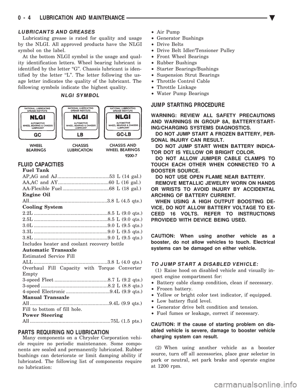
by the NLGI. All approved products have the NLGI
symbol on the label. At the bottom NLGI symbol is the usage and qual-
ity identification letters. Wheel bearing lubricant is
identified by the letter ``G''. Chassis lubricant is iden-
tified by the letter ``L''. The letter following the us-
age letter indicates the quality of the lubricant. The
following symbols indicate the highest quality.
FLUID CAPACITIES
Fuel Tank
AP,AG and AJ ......................................53 L (14 gal.)
AA,AC and AY .....................................60 L (16 gal.)
AA-Flexible Fuel ..................................68 L (18 gal.)
Engine Oil
All.........................................................3.8 L (4.5 qts.)
Cooling System
2.2L ......................................................8.5 L (9.0 qts.)
2.5L ......................................................8.5 L (9.0 qts.)
3.0L ......................................................9.0 L (9.5 qts.)
3.3L ......................................................9.0 L (9.5 qts.)
3.8L ......................................................9.0 L (9.5 qts.)
Includes heater and coolant recovery bottle
Automatic Transaxle
Estimated Service Fill
ALL ......................................................3.8 L (4.0 qts.)
Overhaul Fill Capacity with Torque Converter
Empty
3-speed Fleet .......................................8.7 L (9.2 qts.)
3-speed .................................................8.2 L (8.8 qts.)
4-speed Electronic ................................9.4L (9.9 qts.)
Manual Transaxle
All ..........................................................9.4L (9.9 qts.)
Fill to bottom of fill hole.
Power Steering
All ...........................................................75L (1.5 pts.)
PARTS REQUIRING NO LUBRICATION
Many components on a Chrysler Corporation vehi-
cle require no periodic maintenance. Some compo-
nents are sealed and permanently lubricated. Rubber
bushings can deteriorate or limit damping ability if
lubricated. The following list of components require
no lubrication: ²
Air Pump
² Generator Bushings
² Drive Belts
² Drive Belt Idler/Tensioner Pulley
² Front Wheel Bearings
² Rubber Bushings
² Starter Bearings/Bushings
² Suspension Strut Bearings
² Throttle Control Cable
² Throttle Linkage
² Water Pump Bearings
JUMP STARTING PROCEDURE
WARNING: REVIEW ALL SAFETY PRECAUTIONS
AND WARNINGS IN GROUP 8A, BATTERY/START-
ING/CHARGING SYSTEMS DIAGNOSTICS. DO NOT JUMP START A FROZEN BATTERY, PER-
SONAL INJURY CAN RESULT. DO NOT JUMP START WHEN BATTERY INDICA-
TOR DOT IS YELLOW OR BRIGHT COLOR. DO NOT ALLOW JUMPER CABLE CLAMPS TO
TOUCH EACH OTHER WHEN CONNECTED TO A
BOOSTER SOURCE. DO NOT USE OPEN FLAME NEAR BATTERY.
REMOVE METALLIC JEWELRY WORN ON HANDS
OR WRISTS TO AVOID INJURY BY ACCIDENTAL
ARCHING OF BATTERY CURRENT. WHEN USING A HIGH OUTPUT BOOSTING DE-
VICE, DO NOT ALLOW BATTERY VOLTAGE TO EX-
CEED 16 VOLTS. REFER TO INSTRUCTIONS
PROVIDED WITH DEVICE BEING USED.
CAUTION: When using another vehicle as a
booster, do not allow vehicles to touch. Electrical
systems can be damaged on either vehicle.
TO JUMP START A DISABLED VEHICLE:
(1) Raise hood on disabled vehicle and visually in-
spect engine compartment for:
² Battery cable clamp condition, clean if necessary.
² Frozen battery.
² Yellow or bright color test indicator, if equipped.
² Low battery fluid level.
² Generator drive belt condition and tension.
² Fuel fumes or leakage, correct if necessary.
CAUTION: If the cause of starting problem on dis-
abled vehicle is severe, damage to booster vehicle
charging system can result.
(2) When using another vehicle as a booster
source, turn off all accessories, place gear selector in
park or neutral, set park brake and operate engine
at 1200 rpm.
NLGI SYMBOL
0 - 4 LUBRICATION AND MAINTENANCE Ä
Page 41 of 2438

(3) On disabled vehicle, place gear selector in park
or neutral and set park brake. Turn off all accesso-
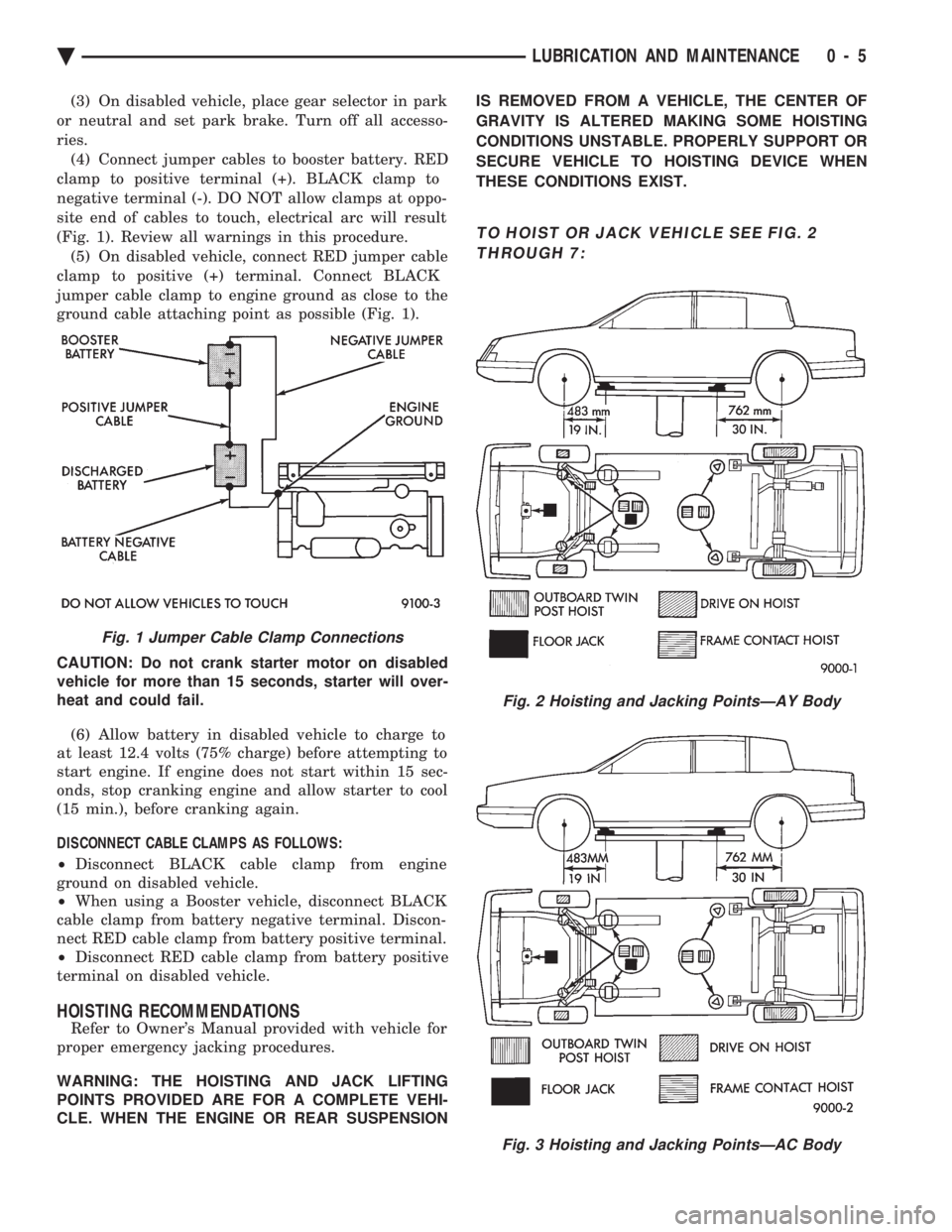
ries. (4) Connect jumper cables to booster battery. RED
clamp to positive terminal (+). BLACK clamp to
negative terminal (-). DO NOT allow clamps at oppo-
site end of cables to touch, electrical arc will result
(Fig. 1). Review all warnings in this procedure. (5) On disabled vehicle, connect RED jumper cable
clamp to positive (+) terminal. Connect BLACK
jumper cable clamp to engine ground as close to the
ground cable attaching point as possible (Fig. 1).
CAUTION: Do not crank starter motor on disabled
vehicle for more than 15 seconds, starter will over-
heat and could fail.
(6) Allow battery in disabled vehicle to charge to
at least 12.4 volts (75% charge) before attempting to
start engine. If engine does not start within 15 sec-
onds, stop cranking engine and allow starter to cool
(15 min.), before cranking again.
DISCONNECT CABLE CLAMPS AS FOLLOWS:
² Disconnect BLACK cable clamp from engine
ground on disabled vehicle.
² When using a Booster vehicle, disconnect BLACK
cable clamp from battery negative terminal. Discon-
nect RED cable clamp from battery positive terminal.
² Disconnect RED cable clamp from battery positive
terminal on disabled vehicle.
HOISTING RECOMMENDATIONS
Refer to Owner's Manual provided with vehicle for
proper emergency jacking procedures.
WARNING: THE HOISTING AND JACK LIFTING
POINTS PROVIDED ARE FOR A COMPLETE VEHI-
CLE. WHEN THE ENGINE OR REAR SUSPENSION IS REMOVED FROM A VEHICLE, THE CENTER OF
GRAVITY IS ALTERED MAKING SOME HOISTING
CONDITIONS UNSTABLE. PROPERLY SUPPORT OR
SECURE VEHICLE TO HOISTING DEVICE WHEN
THESE CONDITIONS EXIST.
TO HOIST OR JACK VEHICLE SEE FIG. 2 THROUGH 7:
Fig. 1 Jumper Cable Clamp Connections
Fig. 2 Hoisting and Jacking PointsÐAY Body
Fig. 3 Hoisting and Jacking PointsÐAC Body
Ä LUBRICATION AND MAINTENANCE 0 - 5
Page 276 of 2438

As soon as the condition goes away, the Anti-Lock
Warning Light is turned off. Although a fault code
will be set in most cases.
BENDIX ABS SYSTEMS DIAGNOSTICS
Bendix Anti-Lock 6 Brake System Diagnostics, be-
yond basic mechanical diagnostics, covered earlier in
this section. Are accomplished by using the DRB II
scan tool. See testing procedures outlined in the Ben-
dix Anti-Lock 6 Diagnostics Manual for the 1992
M.Y. vehicles. Please refer to the above mentioned manual for
any further electronic diagnostics and service proce-
dures that are required on the Bendix Anti-Lock 6
Brake System.
ON-CAR ABS BRAKE SYSTEM SERVICE
GENERAL SERVICE PRECAUTIONS
The following are general cautions which should be
observed when servicing the Anti-Lock brake system
and/or other vehicle systems. Failure to observe
these precautions may result in Anti-Lock Brake
System component damage. If welding work is to be performed on the vehicle,
using an electric arc welder, the (CAB) connector
should be disconnected during the welding operation. The (CAB) connector should never be connected or
disconnected with the ignition switch in the ON po-
sition. Many components of the Anti-Lock Brake System
are not serviceable and must be replaced as an as-
sembly. Do not disassemble any component which is
not designed to be serviced.
CHECKING BRAKE FLUID LEVEL
CAUTION: Only use brake fluid conforming to DOT
3 specifications, such as Mopar or Equivalent. Do
not use any fluid which contains a petroleum base.
Do not use a container which has been used for pe-
troleum based fluids or a container which is wet
with water. Petroleum based fluids will cause swell-
ing and distortion of rubber parts in the hydraulic
brake system. Water will mix with brake fluid, low-
ering the fluid boiling point. Keep all brake fluid
containers capped to prevent contamination. Re-
move the front cap of the master cylinder reservoir
and fill to the bottom of the split ring.
For the specific procedure for the inspection of
brake fluid level and adding of brake to the reser-
voir. Refer to the Service Adjustments Section in this
group of the service manual.
BLEEDING BENDIX ANTI-LOCK 6 BRAKE SYSTEM
The Anti-Lock Brake System must be bled anytime
air is permitted to enter the hydraulic system, due to
disconnection of brake lines, hoses of components. If the Modulator Assembly is removed from the ve-
hicle, both the Base Brake System and the Anti-Lock
Brake System must be bled using the appropriate
procedures. It is important to note that excessive air
in the brake system will cause a soft or spongy feel-
ing brake pedal. During bleeding operations, be sure that the brake
fluid level remains close to the FULL level in the
reservoir. Check the fluid level periodically during
the bleeding procedure and add DOT 3 brake fluid as
required. The Bendix Anti-Lock 6 Brake System must be
bled as two independent braking systems. The non
ABS portion of the brake system is to be bled the
same as any non ABS system. Refer to the Service
Adjustments section in this manual for the proper
bleeding procedure to be used. This brake system can
be either pressure bled or manually bled. The Anti-Lock portion of brake system MUST be
bled separately. This bleeding procedure requires the
use of the DRB II Diagnostic tester and the bleeding
sequence procedure outlined below.
ABS BLEEDING PROCEDURE (FIG. 1)
(1) Assemble and install all brake system compo-
nents on vehicle making sure all hydraulic fluid
lines are installed and properly torqued. (2) Bleed the base brake system. Using the stan-
dard pressure or manual bleeding procedure as out-
lined in the Service Adjustments section of this
service manual. To perform the bleeding procedure on the ABS
unit. The battery and acid shield must be removed
from the vehicle. Reconnect the vehicles battery, to
the vehicles positive and negative battery cables us-
ing jumper cables. This is necessary to allow access
to the 4 bleeder screws located on the top of the Mod-
ulator assembly. (3) Connect the DRB II Diagnostics Tester to the
diagnostics connector. Located behind the Fuse Panel
access cover on the lower section of the dash panel to
the left of the steering column. (It is a blue 6 way
connector). (4) Using the DRB II check to make sure the
(CAB) does not have any fault codes stored. If it does
remove them using the DRB II.
5 - 126 ANTI-LOCK 6 BRAKE SYSTEM Ä
Page 312 of 2438

BENDIX ANTILOCK 4 MODULATOR ASSEMBLY BLEEDING PROCEDURE
(1) Assemble and install all brake system compo-
nents on the vehicle, making sure all hydraulic fluid
lines are installed and properly torqued. (2) Bleed the base brake system, using ONLYthe
bleeding procedure outlined in the Service Adjust-
ments section of this service manual supplement. To perform the bleeding procedure on the ABS modu-
lator assembly, the battery, battery tray and acid shield
must be removed from vehicle. Then reconnect the
vehicle's battery to vehicle's battery cables, using
ONLY approved battery jumper cables. (3) Connect the DRB Diagnostics Tester to the vehi-
cle's diagnostics connector. The vehicle diagnostic con-
nector is located behind the fuse panel access cover on
the lower section of the dash panel left of the steering
column. The diagnostic connector is a blue 6 way
connector. (4) Using the DRB check to make sure the CAB does
not have any stored fault codes. If it does, remove them
using the DRB.
WARNING: WHEN BLEEDING THE MODULATOR AS-
SEMBLY WEAR SAFETY GLASSES. A CLEAR BLEED
TUBE MUST BE ATTACHED TO THE MODULATOR
BLEED SCREWS AND SUBMERGED IN A CLEAR
CONTAINER FILLED PART WAY WITH FRESH CLEAN
BRAKE FLUID. DIRECT THE FLOW OF BRAKE FLUID
AWAY FROM THE PAINTED SURFACES OF THE VE-
HICLE. BRAKE FLUID AT HIGH PRESSURE MAY
COME OUT OF THE BLEEDER SCREWS, WHEN
OPENED.
When bleeding Antilock modulator assembly, the
following bleeding sequence MUSTbe followed to
insure a complete bleeding of all air from the Antilock
brake, and base brake hydraulic systems. The modu-
lator assembly can ONLY be bled using a manual
bleeding procedure to pressurize the hydraulic
system.
MODULATOR ASSEMBLY CIRCUIT BLEEDING PROCEDURE AND SEQUENCE
1 MODULATOR PRIMARY CHECK VALVE CIRCUIT
Note: To bleed hydraulic circuits of the Bendix
Antilock 4 Brake System modulator assembly,
the aid of a second mechanic or helper will be
required to pump the brake pedal. (1) Install a clear bleed tube (such as Tygon) on
primary check valve circuit bleed screw (Fig. 1). Then
install bleed tube into a clear container partially filled
with fresh clean brake fluid (Fig. 1). (2) Pump brake pedal several times, then apply and
hold a constant medium to heavy force on brake pedal. (3) Open primary check valve circuit bleed screw
(Fig. 1) at least 1 full turn to ensure an adequate flow
of brake fluid. Continue bleeding primary check valve
circuit until brake pedal bottoms. (4) After brake pedal bottoms, close and tighten
bleed screw. Then release brake pedal. Do not release
brake pedal prior to closing and tightening bleed
screw. (5) Continue bleeding modulator assembly, repeat-
ing steps 2 through 4 until a clear, bubble free flow of
brake fluid is evident. (6) When all air is bled from primary check valve
circuit, tighten bleed screw and remove bleed hose
from bleed screw. Do not remove bleed hose before
tightening bleed screw, air may re-enter modula-
tor. (7) Torque modulator assembly primary bleed screw
to9N Im (80 in. lbs.).
2 MODULATOR SECONDARY CHECK VALVE CIRCUIT (1) Move clear bleed tube to secondary check valve
circuit bleed screw (Fig. 2). Then install bleed tube into
a container partially filled with fresh clean brake fluid
(Fig. 2). (2) Pump brake pedal several times, then apply and
hold a constant medium to heavy force on brake pedal. (3) Open secondary check valve circuit bleeder screw
(Fig. 2), at least 1 full turn to ensure an adequate flow
of brake fluid. Continue to bleed secondary check valve
circuit until the brake pedal bottoms.
Fig. 1 Bleeding Modulator Assembly Primary Check Valve Circuit
5 - 26 ANTILOCK 4 BRAKE SYSTEM Ä
Page 319 of 2438

(10) Using approved battery jumper cables, attach
battery, to the vehicles negative and positive battery
cables (Fig. 17). (11) Bleed the vehicles base brake and Antilock
brake hydraulic systems. Refer to Bleeding Bendix
Antilock 4 Brake System in this service manual
supplement for required bleeding procedure. (12) Install the battery acid shield (Fig. 18) onto
modulator assembly. Be sure acid shield is securely
attached to modulator assembly before installing
battery tray. (13) Install battery tray in vehicle. Then install the 4
bolts (Fig. 19) attaching battery tray to inner fender
and frame rail. Torque the 4 attaching bolts to 20 N Im
(175 in.lbs.). (14) If equipped, install speed control vacuum reser-
voir on battery tray. Then install the 2 speed control
vacuum reservoir attaching bolts (Fig. 20). Torque the
vacuum reservoir to attaching bolts to 4 N Im (30 in.
lbs.). (15) Install battery tray access cover (Fig. 21) on
battery tray. The access cover MUST be back on
battery tray, before battery is installed in battery
tray. (16) Install battery on battery tray. Then install and
securely tighten battery hold down clamp (Fig. 22).
Then install battery heat shield, on battery (Fig. 22). (17) Install battery cables on battery. Securely
tighten clamping bolts on battery cable terminals.
Fig. 15 Hydraulic Brake Line Connections at Modulator Assembly
Fig. 16 Torquing Brake Line Connections To Modulator Assembly
Fig. 17 Battery Connected To Vehicle For Bleeding Modulator Assembly
Fig. 18 Modulator Assembly Acid Shield Installed
Ä ANTILOCK 4 BRAKE SYSTEM 5 - 33
Page 322 of 2438

(12) Remove hydraulic brake tube assembly rout-
ing bracket, from the engine mounting bracket (Fig.
10). (13) Remove the 6 hydraulic brake tubes and rout-
ing bracket as an assembly from the vehicle.
INSTALL (1) Install the 6 hydraulic brake tubes, clips and
routing bracket as an assembly into the vehicle. (2) Align the 6 hydraulic brake tubes with their
correct locations on the junction block. Thread the 6
brake line tube nuts by handinto the junction block
tube ports. Then torque all 6 brake tube nuts to 18
N Im (159 in.lbs.).
(3) Install the primary and secondary hydraulic
brake tubes, from master cylinder to junction block
(Fig. 9). Then torque the brake line tube nuts at both
the master cylinder and junction block to 18 N Im
(159 in. lbs.). (4) Install the hydraulic brake tube assembly rout-
ing bracket onto the engine mounting bracket (Fig. 10). Torque the brake tube routing bracket attaching
bolt to 11 N
Im (95 in. lbs.).
(5) Align the 6 hydraulic brake lines with their ap-
propriate fitting locations on the modulator assembly
(Fig. 11). Thread the 6 brake line tube nuts by hand
into proportioning valves and thread savers on mod-
ulator assembly. (6) Using a crow foot and torque wrench (Fig. 12),
torque the 6 hydraulic brake line tube nuts to 18
N Im (159 in. lbs.).
(7) Using approved battery jumper cables, attach
battery, to the vehicles negative and positive battery
cables (Fig. 13). (8) Bleed the vehicles base brake and Antilock
brake hydraulic systems. Refer to Bleeding Bendix
Fig. 7 Hydraulic Brake Line Connections To Modulator Assembly
Fig. 8 Pressure Differential Switch Assembly
Fig. 9 Brake Tubes From Master Cylinder To Junction Block
Fig. 10 Brake Tube Routing Bracket
5 - 36 ANTILOCK 4 BRAKE SYSTEM Ä
Page 326 of 2438

against modulator assembly. Then torque proportion-
ing valve to 35 N Im (26 ft. lbs.) torque.
(3) Install hydraulic brake line on proportioning
valve and hand start tube nut into proportioning valve.
Torque tube nut to 18 N Im (159 in. lbs.) torque.
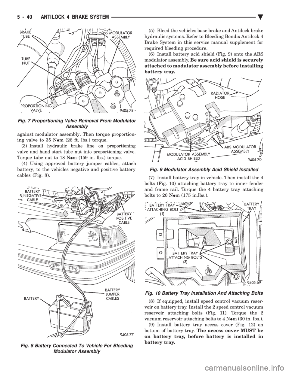
(4) Using approved battery jumper cables, attach
battery, to the vehicles negative and positive battery
cables (Fig. 8). (5) Bleed the vehicles base brake and Antilock brake
hydraulic systems. Refer to Bleeding Bendix Antilock 4
Brake System in this service manual supplement for
required bleeding procedure. (6) Install battery acid shield (Fig. 9) onto the ABS
modulator assembly. Be sure acid shield is securely
attached to modulator assembly before installing
battery tray.
(7) Install battery tray in vehicle. Then install the 4
bolts (Fig. 10) attaching battery tray to inner fender
and frame rail. Torque the 4 battery tray attaching
bolts to 20 N Im (175 in.lbs.).
(8) If equipped, install speed control vacuum reser-
voir on battery tray. Install the 2 speed control vacuum
reservoir attaching bolts (Fig. 11). Torque the 2
vacuum reservoir attaching bolts to 4 N Im (30 in. lbs.).
(9) Install battery tray access cover (Fig. 12) on
bottom of battery tray. The access cover MUST be
on battery tray, before battery is installed in
battery tray.
Fig. 8 Battery Connected To Vehicle For Bleeding Modulator Assembly
Fig. 7 Proportioning Valve Removal From Modulator Assembly
Fig. 9 Modulator Assembly Acid Shield Installed
Fig. 10 Battery Tray Installation And Attaching Bolts
5 - 40 ANTILOCK 4 BRAKE SYSTEM Ä
Page 382 of 2438

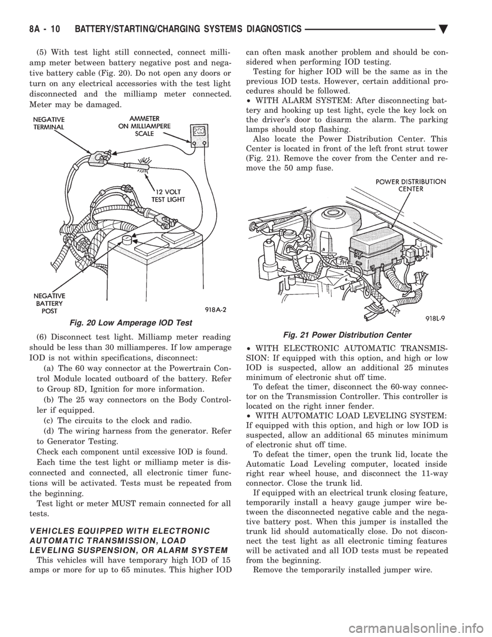
(5) With test light still connected, connect milli-
amp meter between battery negative post and nega-
tive battery cable (Fig. 20). Do not open any doors or
turn on any electrical accessories with the test light
disconnected and the milliamp meter connected.
Meter may be damaged.
(6) Disconnect test light. Milliamp meter reading
should be less than 30 milliamperes. If low amperage
IOD is not within specifications, disconnect: (a) The 60 way connector at the Powertrain Con-
trol Module located outboard of the battery. Refer
to Group 8D, Ignition for more information. (b) The 25 way connectors on the Body Control-
ler if equipped. (c) The circuits to the clock and radio.
(d) The wiring harness from the generator. Refer
to Generator Testing.
Check each component until excessive IOD is found.
Each time the test light or milliamp meter is dis-
connected and connected, all electronic timer func-
tions will be activated. Tests must be repeated from
the beginning. Test light or meter MUST remain connected for all
tests.
VEHICLES EQUIPPED WITH ELECTRONIC AUTOMATIC TRANSMISSION, LOADLEVELING SUSPENSION, OR ALARM SYSTEM
This vehicles will have temporary high IOD of 15
amps or more for up to 65 minutes. This higher IOD can often mask another problem and should be con-
sidered when performing IOD testing. Testing for higher IOD will be the same as in the
previous IOD tests. However, certain additional pro-
cedures should be followed.
² WITH ALARM SYSTEM: After disconnecting bat-
tery and hooking up test light, cycle the key lock on
the driver's door to disarm the alarm. The parking
lamps should stop flashing. Also locate the Power Distribution Center. This
Center is located in front of the left front strut tower
(Fig. 21). Remove the cover from the Center and re-
move the 50 amp fuse.
² WITH ELECTRONIC AUTOMATIC TRANSMIS-
SION: If equipped with this option, and high or low
IOD is suspected, allow an additional 25 minutes
minimum of electronic shut off time. To defeat the timer, disconnect the 60-way connec-
tor on the Transmission Controller. This controller is
located on the right inner fender.
² WITH AUTOMATIC LOAD LEVELING SYSTEM:
If equipped with this option, and high or low IOD is
suspected, allow an additional 65 minutes minimum
of electronic shut off time. To defeat the timer, open the trunk lid, locate the
Automatic Load Leveling computer, located inside
right rear wheel house, and disconnect the 11-way
connector. Close the trunk lid. If equipped with an electrical trunk closing feature,
temporarily install a heavy gauge jumper wire be-
tween the disconnected negative cable and the nega-
tive battery post. When this jumper is installed the
trunk lid should automatically close. Do not discon-
nect the test light as all electronic timing features
will be activated and all IOD tests must be repeated
from the beginning. Remove the temporarily installed jumper wire.
Fig. 20 Low Amperage IOD Test
Fig. 21 Power Distribution Center
8A - 10 BATTERY/STARTING/CHARGING SYSTEMS DIAGNOSTICS Ä