1993 CHEVROLET PLYMOUTH ACCLAIM oil reset
[x] Cancel search: oil resetPage 243 of 2438
DRIVE-OFF CYCLE
The DRIVE-OFF CYCLE takes place when the ve-
hicle reaches about 3 miles per hour the first time af-
ter an ignition reset. During this test, the modulator
solenoid valves are activated briefly to test their
function. The DRIVE-OFF CYCLE will be bypassed
if you drive-off with the service brake pedal de-
pressed.
LATCHING VERSUS NON-LATCHING FAULTS
Some faults detected by the (CAB) are latching.
The fault is latched and (ABS) function is disabled
until the ignition switch is reset (turned OFF/ON).
Thus (ABS) function is disabled even if the original
fault has disappeared during the ignition cycle in
which it occurred. Other faults are non-latching; any
warning lights that are turned on are only on as long
as the fault condition exists. As soon as the condition
goes away. The Amber Anti-Lock Warning Light is
turned off. Although a fault code will be set in most
cases. (Example:low accumulator fault will not be
stored for a time of 2 minutes after the fault is de-
tected).
BENDIX ABS SYSTEMS DIAGNOSTICS
The Bendix Anti-Lock 10 Brake System diagnos-
tics. Beyond the basic mechanical diagnostics, sys-
tems and components covered earlier in this section,
is accomplished by using the DRB II diagnostic
tester. See testing procedures outlined in the Bendix
Anti-Lock 10 Diagnostics Manual for the 1993 M.Y. Please reference the above mentioned manual. For
any further diagnostic service procedures that are re-
quired on the Bendix Anti-Lock 10 Brake System, re-
quiring the use of the DRB II diagnostic tester.
ON CAR HYDRAULIC ABS COMPONENT SERVICE
WARNING: FAILURE TO FULLY DE-PRESSURIZE
THE HYDRAULIC ACCUMULATOR BEFORE PER-
FORMING HYDRAULIC SYSTEM SERVICE OPERA-
TIONS. COULD RESULT IN INJURY TO SERVICE
PERSONNEL AND OR DAMAGE TO PAINTED SUR-
FACES. SEE SECTION 2 FOR ADDITIONAL WARN-
INGS AND CAUTIONS.
GENERAL SERVICE PRECAUTIONS
The following are general precautions that should
be observed when servicing the Anti-Lock Brake Sys-
tem and/or other vehicle systems. Failure to observe
these precautions may result in Anti-Lock brake sys-
tem damage. If welding work is to be performed on the vehicle,
using an electric arc welder, the (CAB) connector
should be disconnected during the welding operation. The (CAB) or hydraulic assembly connector should
never be connected or disconnected with the ignition
switch in the ONposition.
Many components of the Anti-Lock brake system are
not serviceable and must be replaced as an assembly.
Do not attempt to disassemble any component
that is not designed to be a serviced component.
DE-PRESSURIZING HYDRAULIC ACCUMULA- TOR
The pump/motor assembly will keep the hydraulic
accumulator charged to approximately 11,032 and
13,790 kPa (1600 and 2000 psi) any time that the
ignition is in the ON position. The pump/motor assem-
bly cannot run if the ignition is off or if either battery
cable is disconnected. Unless otherwise specified, the hydraulic accumula-
tor should be de-pressurized before disassembling any
portion of the hydraulic system. The following proce-
dure should be used to relieve the pressure in the
hydraulic accumulator: (1) With ignition off, or either battery cable discon-
nected, pump the brake pedal a minimum of 40 times,
using approximately 222 N (50 lbs.) pedal force. A
noticeable change in pedal feel will occur, when the
accumulator is discharged. (2) When a definite increase in pedal effort is felt,
pump pedal a few additional times. This will insure
removal of all hydraulic pressure from the brake sys-
tem.
CHECKING BRAKE FLUID LEVEL
CAUTION: Use only brake fluid conforming to DOT 3
specifications such as Mopar Tor Equivalent. Do not
use any fluid in the brake hydraulic system, which
contains a petroleum base. Do not use a container
which has been used for petroleum based fluids or a
container that is wet with water. Petroleum based
fluids will cause swelling and distortion of rubber
parts in the hydraulic brake system and water will mix
with brake fluid, lowering the fluid boiling point. Keep
all brake fluid containers tightly capped to prevent
contamination.
The hydraulic assembly is equipped with a plastic
fluid reservoir, with a filter/strainer located in the filler
neck of each reservoir section. The Anti-Lock brake system requires that the hy-
draulic accumulator be de-pressurized when checking
the fluid level. To check the brake fluid level, the
following procedure should be used: (1) With the ignition off, de-pressurize the hydraulic
accumulator by applying the brake pedal approxi-
mately 40 times, using a pedal force of approximately
220 N (50 lbs.). A noticeable change in pedal feel will
occur when the accumulator is de-
Ä ANTI-LOCK 10 BRAKE SYSTEM 5 - 93
Page 311 of 2438
LATCHING VERSUS NON-LATCHING ABS FAULTS
Some faults detected by the CAB are latching; the
fault is latched and ABS is disabled until the igni-
tion switch is reset. Thus ABS is disabled even if the
original fault has disappeared. Other faults are non-
latching; any warning lights that are turned on, are
only turned on as long as the fault condition exists.
As soon as the condition goes away, the Antilock
Warning Light is turned off. Although a fault code
will be set in most cases.
BENDIX ANTILOCK 4 BRAKE SYSTEM DIAGNOSTICS
Bendix Antilock 4 Brake System Diagnostics, be-
yond basic mechanical diagnostics, covered earlier in
this section, are accomplished by using the DRB scan
tool. See testing procedures outlined in the 1994 Ben-
dix Antilock 4 Diagnostics Manual. Please refer to the above mentioned manual for
any further electronic diagnostics and service proce-
dures that are required on the Bendix Antilock 4
Brake System.
ON-CAR ABS BRAKE SYSTEM SERVICE
GENERAL SERVICE PRECAUTIONS
The following are general cautions which should be
observed when servicing the Bendix Antilock 4
Brake System and other vehicle electronic systems.
Failure to observe these precautions may result in
Antilock Brake System component damage. If welding work is to be performed on a vehicle us-
ing an electric arc welder, disconnect the 60 way wir-
ing harness connector from the CAB, prior to
performing the welding operation. The wiring harness connector should never be con-
nected or disconnected from the CAB with the igni-
tion key in the ON or Run position. (3) Most components making up the assemblies of
the Bendix Antilock 4 Brake System can not be ser-
viced separately from those assemblies. This will re-
quire replacement of the complete assembly for the
servicing of these components. Do not disassemble
any component from an assembly which is desig-
nated as non-serviceable.
CHECKING BRAKE FLUID LEVEL
CAUTION: Only use brake fluid conforming to DOT
3 specifications, such as Mopar or Equivalent. Do
not use any fluid which contains a petroleum base.
Do not use a container which has been used for pe-
troleum based fluids or a container which is wet
with water. Petroleum based fluids will cause swell-
ing and distortion of rubber parts in the hydraulic
brake system. Water will mix with brake fluid, low-
ering the boiling point of the brake fluid, possibly causing brake fluid to boil resulting in brake fade.
Keep all brake fluid containers capped to prevent
contamination. Remove the front cap of the master
cylinder reservoir and fill to the bottom of the split
ring.
For the specific procedure for the inspection of
brake fluid level and adding of brake to the reser-
voir. Refer to the Service Adjustments Section in this
group of the service manual.
BLEEDING BENDIX ANTILOCK 4 BRAKE SYSTEM
The base brakes and Antilock Brake System must
be bled anytime air is permitted to enter the hydrau-
lic system, due to disconnection of brake lines, hoses
or components. If the Antilock Modulator Assembly is removed
from the vehicle, both the Base Brake System and
the Antilock Brake System must be bled using the
appropriate procedure. It is important to note that
excessive air in the brake system will cause a soft or
spongy feeling brake pedal. During brake bleeding operations, ensure that
brake fluid level remains close to the FULL level in
the reservoir. Check brake fluid level periodically
during bleeding procedure, adding DOT 3 brake fluid
as required.
CAUTION: The base brake and Antilock brake hy-
draulic systems, on the Bendix Antilock 4 Brake
System, can NOT be bled using any type of brake
pressure bleeding equipment. This type of bleeding
equipment does not develop the pressure required
in the brake hydraulic system, to adequately bleed
all trapped air. The only approved method for bleed-
ing air out of the hydraulic system on vehicles
equipped with the Bendix Antilock 4 Brake System,
is the manual procedure of pressurizing the hydrau-
lic system using constant, moderate to heavy foot
pressure on the brake pedal.
The Bendix Antilock 4 Brake System must be bled
as two independent brake systems. The non ABS por-
tion of the brake system is to be bled the same as
any non ABS system. Refer to the Service Adjust-
ments section in this manual for the proper bleeding
procedure to be used. The Bendix Antilock 4 Brake
System can only be bled using a manual method of
pressurizing the brakes hydraulic system. The Antilock portion of brake system MUST be
bled separately. This bleeding procedure requires the
use of the DRB Diagnostic tester and the bleeding se-
quence procedure outlined below.
Ä ANTILOCK 4 BRAKE SYSTEM 5 - 25
Page 423 of 2438

² To set DAY of WEEK, press TIME button. An ar-
row will appear on the display and point to the Day.
Press and hold the SET button to move the day for-
ward or INFO button to move it backward.
² To set DAY of MONTH, press TIME button. The
arrow will point to Date. Press and hold the SET
button to advance the date or INFO button to move
it backwards.
² To set MONTH of YEAR, press TIME button. The
arrow will point to the Month. Press and hold the
SET button to advance the Month forward or INFO
button to move backward. TEMP button, pressing the Temp button will dis-
play:
² The temperature outside the vehicle
² Vehicle direction define by an eight point compass
If Compass has lost calibration or not receiving
good information from the engine compartment node,
an asterisk (*) will flash on the display and the word
calibrate will appear. Refer to Compass Calibration. FUEL BUTTON, WILL DISPLAY:
² Pressing FUEL button the first time will show, the
estimated number of miles that can be driven with
the remaining fuel. The destination to empty indica-
tion will vary every few seconds as the amount of
fuel and fuel efficiency is calculated. This function
can not be reset.
² Pressing the FUEL button second time; will dis-
play the fuel consumed.
²
Pressing the FUEL button third time; will display
the average fuel economy in miles per gallon since last
reset. The display will be updated every 16 seconds.
² Pressing the FUEL button forth time, the current
fuel economy will be displayed. The current fuel
economy will be up updated every two seconds.
² To reset Fuel consumed, press SET button until
the fuel consumed message is displayed and then
within five seconds press SET button.
² To reset AVERAGE FUEL ECONOMY, press the
FUEL button until average fuel economy is displayed
and within five seconds press SET button. TRIP RESET, press FUEL button and wait four
seconds press the SET button twice. This clears all
trip information and the message Trip Reset will be
displayed. This will occur only if a reset function is
currently being displayed. The reset functions:
² Fuel consumed
² Average fuel economy message
INFO button, will active a MONITORED SYS-
TEMS OK message on display if all monitored sys-
tems are operating properly. If a problem is detected,
the appropriate message will be displayed. SET button, will clear the various functions after
they have been displayed. It is used to enter the
clock set or compass variance modes. This button is
also used to reset certain trip computer functions and
the maintenance reminder message.
The EVIC display may be turned off by pressing the
TIME and SET buttons at the same time. Pressing the
buttons a second time will restore the display.
EVIC INFORMATION SOURCES
The EVIC monitors information provided by the
body controller, engine compartment node and pow-
ertrain control module. Refer to Body Diagnostic Test
Procedure Manual for test procedures. The Body Controller is a micro-controller unit
which, informs the EVIC overhead console via the
CCD bus of:
² Time of day
² Day of week
² Day of month
² Month of year
² Fuel range
² Fuel consumed
² Fuel efficiency
² Warning messages as noted in Fig. 2
The Engine Compartment Node is a microcomputer
controlled unit which, informs the EVIC overhead
console via the CCD bus of:
² Outside temperature
² Compass direction
THE FOLLOWING ARE WARNING MESSAGES:
² Low brake fluid
² Low coolant level
² Low engine oil level
The powertrain control module is a microcomputer
controlled unit which, informs the EVIC overhead con-
sole via the CCD bus of the following warning messages:
² Engine temperature high
² Voltage improper
Fig. 2 EVIC Messages and Sensors
Ä OVERHEAD CONSOLE 8C - 7
Page 430 of 2438

dition exists. These messages are displayed on the
center of the instrument panel.For complete EVIC operating instructions, refer to
the Owners Manual provided with the vehicle.
EVIC BUTTON FUNCTIONS
TIME button will display:
² Time of day
² Day of week
² Day of month
² Month of year
² To set HOURS, press TIME button and within four
seconds press the SET button. An arrow will appear
on the display and point to the hours. Press and hold
the SET button to advance the hours or INFO button
to set back the hours.
² To set MINUTES, press TIME button. The arrow
will point to the minutes. Press and hold the SET
button to advance the minutes or INFO button to set
back the minutes.
² To set DAY of WEEK, press TIME button. An ar-
row will appear on the display and point to the Day.
Press and hold the SET button to move the day for-
ward or INFO button to move it backward.
² To set DAY of MONTH, press TIME button. The
arrow will point to Date. Press and hold the SET
button to advance the date or INFO button to move
it backwards.
² To set MONTH of YEAR, press TIME button. The
arrow will point to the Month. Press and hold the
SET button to advance the Month forward or INFO
button to move backward. TEMP button, pressing the Temp button will dis-
play:
² The temperature outside the vehicle
² Vehicle direction define by an eight point compass
If Compass has lost calibration or not receiving
good information from the engine compartment node,
an asterisk (*) will flash on the display and the word
calibrate will appear. Refer to Compass Calibration. FUEL BUTTON, WILL DISPLAY:
² Pressing FUEL button the first time will show, the
estimated number of miles that can be driven with
the remaining fuel. The destination to empty indica-
tion will vary every few seconds as the amount of
fuel and fuel efficiency is calculated. This function
can not be reset.
² Pressing the FUEL button second time; will dis-
play the fuel consumed.
² Pressing the FUEL button third time; will display
the average fuel economy in miles per gallon since
last reset. The display will be updated every 16 sec-
onds.
² Pressing the FUEL button forth time, the current
fuel economy will be displayed. The current fuel
economy will be up updated every two seconds. ²
To reset Fuel consumed, press SET button until
the fuel consumed message is displayed and then
within five seconds press SET button.
² To reset AVERAGE FUEL ECONOMY, press the
FUEL button until average fuel economy is displayed
and within five seconds press SET button. TRIP RESET, press FUEL button and wait four
seconds press the SET button twice. This clears all
trip information and the message Trip Reset will be
displayed. This will occur only if a reset function is
currently being displayed. The reset functions:
² Fuel consumed
² Average fuel economy message
INFO button, will active a MONITORED SYS-
TEMS OK message on display if all monitored sys-
tems are operating properly. If a problem is detected,
the appropriate message will be displayed. SET button, will clear the various functions after
they have been displayed. It is used to enter the
clock set or compass variance modes. This button is
also used to reset certain trip computer functions and
the maintenance reminder message. The EVIC display may be turned off by pressing
the TIME and SET buttons at the same time. Press-
ing the buttons a second time will restore the dis-
play.
EVIC INFORMATION SOURCES
The EVIC monitors information provided by the
body controller, engine compartment node and pow-
ertrain control module. Refer to Body Diagnostic Test
Procedure Manual for test procedures. The Body Controller is a micro-controller unit
which, informs the EVIC via the CCD bus of:
² Time of day
² Day of week
² Day of month
² Month of year
² Fuel range
² Fuel consumed
² Fuel efficiency
² Warning messages as noted in Fig. 3.
The Engine Compartment Node is a microcomputer
controlled unit which, informs the EVIC via the CCD
bus of:
² Outside temperature
² Compass direction
THE FOLLOWING ARE WARNING MESSAGES:
² Low brake fluid
² Low coolant level
² Low engine oil level
The powertrain control module is a microcomputer
controlled unit which, informs the EVIC via the CCD
bus of the following warning messages:
² Engine temperature high
² Voltage improper
8C - 14 OVERHEAD CONSOLE Ä
Page 517 of 2438
off, there should be continuity in the system. Start
the engine. With the engine running, the ohmmeter
should show no continuity. If the above results are
not obtained, replace the switch.
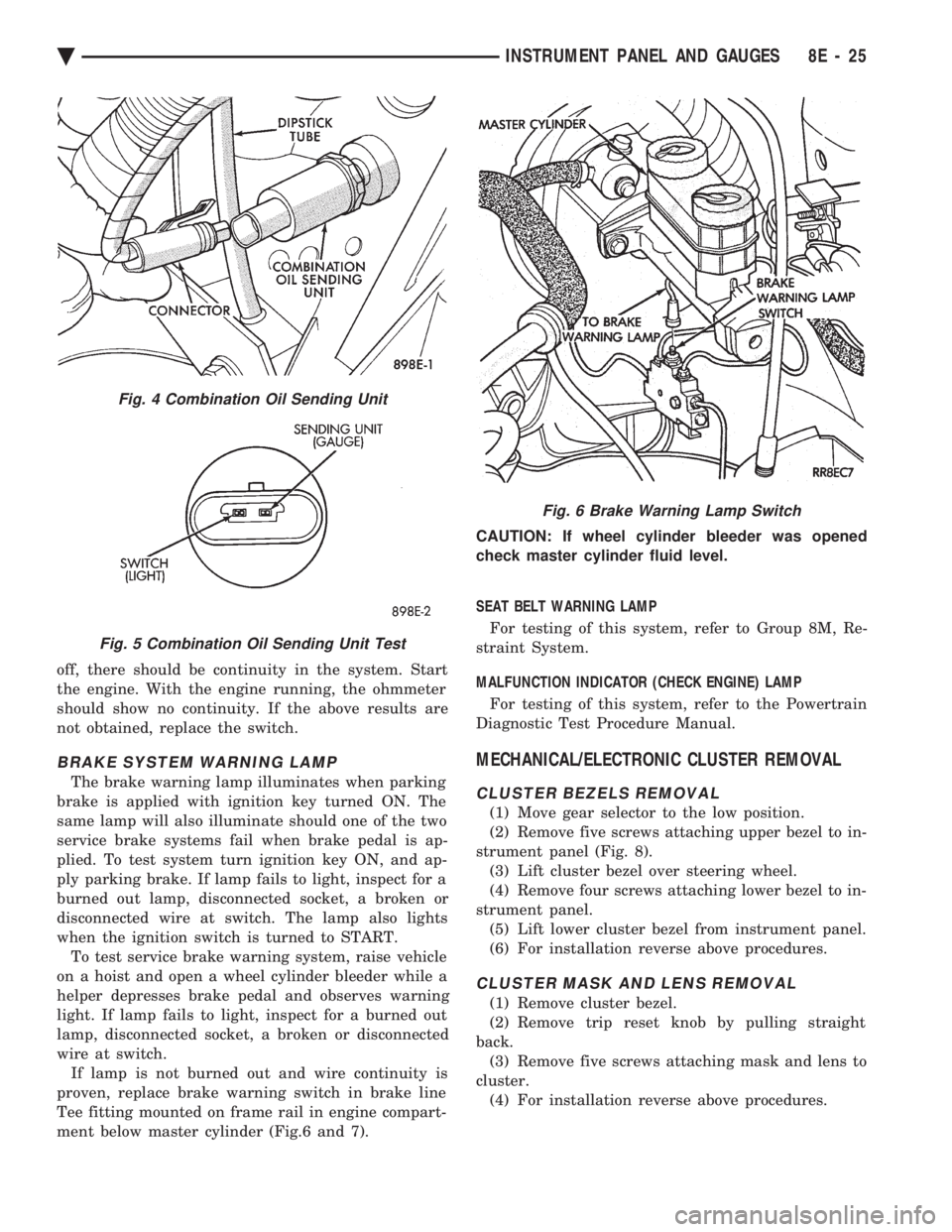
BRAKE SYSTEM WARNING LAMP
The brake warning lamp illuminates when parking
brake is applied with ignition key turned ON. The
same lamp will also illuminate should one of the two
service brake systems fail when brake pedal is ap-
plied. To test system turn ignition key ON, and ap-
ply parking brake. If lamp fails to light, inspect for a
burned out lamp, disconnected socket, a broken or
disconnected wire at switch. The lamp also lights
when the ignition switch is turned to START. To test service brake warning system, raise vehicle
on a hoist and open a wheel cylinder bleeder while a
helper depresses brake pedal and observes warning
light. If lamp fails to light, inspect for a burned out
lamp, disconnected socket, a broken or disconnected
wire at switch. If lamp is not burned out and wire continuity is
proven, replace brake warning switch in brake line
Tee fitting mounted on frame rail in engine compart-
ment below master cylinder (Fig.6 and 7). CAUTION: If wheel cylinder bleeder was opened
check master cylinder fluid level.
SEAT BELT WARNING LAMP
For testing of this system, refer to Group 8M, Re-
straint System.
MALFUNCTION INDICATOR (CHECK ENGINE) LAMP
For testing of this system, refer to the Powertrain
Diagnostic Test Procedure Manual.
MECHANICAL/ELECTRONIC CLUSTER REMOVAL
CLUSTER BEZELS REMOVAL
(1) Move gear selector to the low position.
(2) Remove five screws attaching upper bezel to in-
strument panel (Fig. 8). (3) Lift cluster bezel over steering wheel.
(4) Remove four screws attaching lower bezel to in-
strument panel. (5) Lift lower cluster bezel from instrument panel.
(6) For installation reverse above procedures.
CLUSTER MASK AND LENS REMOVAL
(1) Remove cluster bezel.
(2) Remove trip reset knob by pulling straight
back. (3) Remove five screws attaching mask and lens to
cluster. (4) For installation reverse above procedures.
Fig. 4 Combination Oil Sending Unit
Fig. 5 Combination Oil Sending Unit Test
Fig. 6 Brake Warning Lamp Switch
Ä INSTRUMENT PANEL AND GAUGES 8E - 25
Page 1587 of 2438
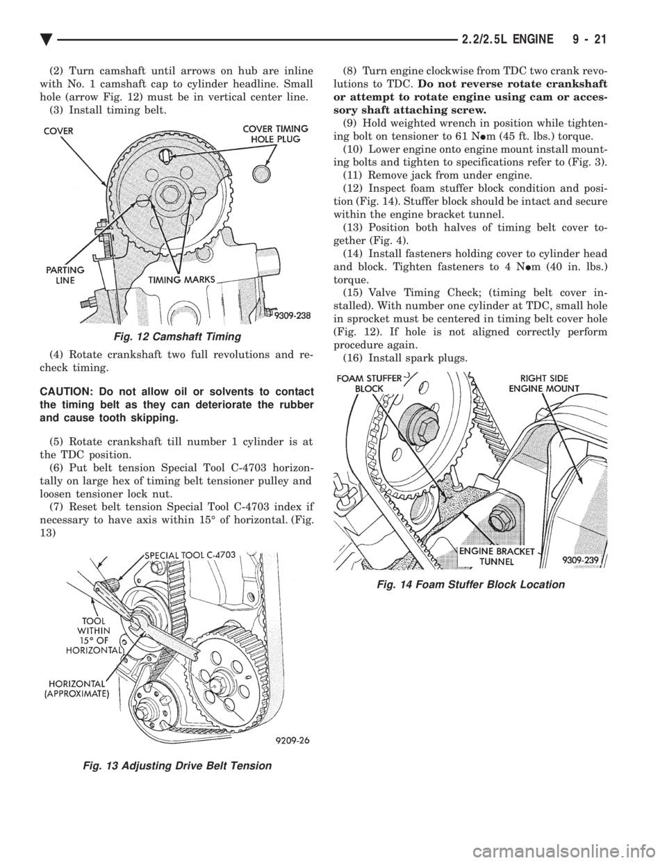
(2) Turn camshaft until arrows on hub are inline
with No. 1 camshaft cap to cylinder headline. Small
hole (arrow Fig. 12) must be in vertical center line. (3) Install timing belt.
(4) Rotate crankshaft two full revolutions and re-
check timing.
CAUTION: Do not allow oil or solvents to contact
the timing belt as they can deteriorate the rubber
and cause tooth skipping.
(5) Rotate crankshaft till number 1 cylinder is at
the TDC position. (6) Put belt tension Special Tool C-4703 horizon-
tally on large hex of timing belt tensioner pulley and
loosen tensioner lock nut. (7) Reset belt tension Special Tool C-4703 index if
necessary to have axis within 15É of horizontal. (Fig.
13) (8) Turn engine clockwise from TDC two crank revo-
lutions to TDC. Do not reverse rotate crankshaft
or attempt to rotate engine using cam or acces-
sory shaft attaching screw. (9) Hold weighted wrench in position while tighten-
ing bolt on tensioner to 61 N Im (45 ft. lbs.) torque.
(10) Lower engine onto engine mount install mount-
ing bolts and tighten to specifications refer to (Fig. 3). (11) Remove jack from under engine.
(12) Inspect foam stuffer block condition and posi-
tion (Fig. 14). Stuffer block should be intact and secure
within the engine bracket tunnel. (13) Position both halves of timing belt cover to-
gether (Fig. 4). (14) Install fasteners holding cover to cylinder head
and block. Tighten fasteners to 4 N Im (40 in. lbs.)
torque. (15) Valve Timing Check; (timing belt cover in-
stalled). With number one cylinder at TDC, small hole
in sprocket must be centered in timing belt cover hole
(Fig. 12). If hole is not aligned correctly perform
procedure again. (16) Install spark plugs.
Fig. 12 Camshaft Timing
Fig. 13 Adjusting Drive Belt Tension
Fig. 14 Foam Stuffer Block Location
Ä 2.2/2.5L ENGINE 9 - 21
Page 1772 of 2438
TACHOMETERÐPCM OUTPUT
The PCM supplies engine RPM to the instrument
panel tachometer. Refer to Group 8 for tachometer
information.
MODES OF OPERATION
As input signals to the PCM change, the PCM
adjusts its response to the output devices. For example,
the PCM must calculate a different injector pulse
width and ignition timing for idle than it does for wide
open throttle (WOT). There are several different modes
of operation that determine how the PCM responds to
the various input signals. There are two different areas of operation, OPEN
LOOP and CLOSED LOOP. During OPEN LOOP modes, the PCM receives input
signals and responds according to preset PCM pro-
gramming. Input from the oxygen (O
2) sensor is not
monitored during OPEN LOOP modes. During CLOSED LOOP modes, the PCM does moni-
tor the oxygen (O
2) sensor input. This input tells the
PCM if the calculated injector pulse width results in an
air-fuel ratio of 14.7 to 1. By monitoring the exhaust
oxygen content, the can PCM fine tune injector pulse
width for optimum fuel economy and low emissions. The single point fuel injection system has the follow-
ing modes of operation:
² Ignition switch ON - Zero RPM
² Engine start-up
² Engine warm-up
² Cruise (Idle)
² Acceleration
² Deceleration
² Wide Open Throttle
² Ignition switch OFF
The engine start-up (cranking), engine warm-up, and
wide open throttle modes are OPEN LOOP modes. The
acceleration, deceleration, and cruise modes, with the
engine at operating temperature are CLOSED
LOOP modes (under most operating conditions).
IGNITION SWITCH ON (ZERO RPM) MODE
When the single point fuel injection system is acti-
vated by the ignition switch, the following actions
occur:
² The PCM determines atmospheric air pressure from
the MAP sensor input to calculate basic fuel strategy.
² The PCM monitors the coolant temperature sensor
and throttle position sensor inputs. The PCM modifies
fuel strategy based on these inputs. When the key is in the ON position and the engine is
not running, the (ASD) and fuel pump relays are not
energized. Therefore, battery voltage is not supplied to
the fuel pump, ignition coil, fuel injector or oxygen
sensor heating element. ENGINE START-UP MODE
This is an OPEN LOOP mode. The following actions
occur when the starter motor is engaged. If the PCM receives a distributor signal it energizes
the auto shutdown (ASD) relay and fuel pump relay to
supply battery voltage to the fuel injector, ignition coil
and oxygen sensor heating element. If the PCM does
not receive a distributor input, it de-energizes the ASD
and fuel pump relays after approximately one second. When the engine idles within 664 RPM of the target
RPM, the PCM compares the current MAP value with
the atmospheric pressure value it received during the
Ignition Switch On (Zero RPM) Mode. If a minimum
difference between the two is not detected, a MAP
sensor fault is set into memory. Once the ASD relay and fuel pump relay have ener-
gized, the PCM:
² Supplies a ground path to the injector. The injector
is pulsed four times per engine revolution instead of
the normal two pulses per revolution.
² Determines injector pulse width based on coolant
temperature, MAP sensor input, throttle position, and
the number of engine revolutions since cranking was
initiated.
² Monitors the coolant temperature sensor, distribu-
tor pick-up, MAP sensor, and throttle position sensor to
determine correct ignition timing.
ENGINE WARM-UP MODE
This is a OPEN LOOP mode. The following inputs
are received by the PCM:
² coolant temperature
² manifold absolute pressure (MAP)
² engine speed (distributor pick-up)
² throttle position
² A/C switch
² battery voltage
The PCM provides a ground path for the injector to
precisely control injector pulse width (by switching the
ground on and off) and fires the injector twice per
engine revolution. The PCM regulates ignition timing.
It also adjusts engine idle speed through the idle air
control motor.
CRUISE OR IDLE MODE
When the engine is at operating temperature this is
a CLOSED LOOP mode. During cruising speed and at
idle the following inputs are received by the PCM:
² coolant temperature
² manifold absolute pressure
² engine speed
² throttle position
² exhaust gas oxygen content
² A/C control positions
² battery voltage
14 - 32 FUEL SYSTEMS Ä
Page 1803 of 2438
mode, the PCM compensates for the failure of certain
components that send incorrect signals. The PCM
substitutes for the incorrect signals with inputs from
other sensors and by using stored default values.Signals that can trigger the Malfunction Indi-
cator (Check Engine) Lamp.
² An emission system component
² Battery Voltage Input
² Charging system
² Engine Coolant Temperature Sensor
² Manifold Absolute Pressure Sensor
² Methanol Concentration Sensor
² Throttle Position Sensor
The malfunction indicator lamp can also display
diagnostic trouble codes. Cycle the ignition switch on,
off, on, off, on, within five seconds and the PCM
displays any diagnostic trouble codes stored in
memory. Refer to the 2.5L Flexible Fuel Multi-Port
Fuel InjectionÐOn Board Diagnostics section in this
group for diagnostic trouble code descriptions.
RADIATOR FAN RELAYÐPCM OUTPUT
The radiator fan is energized by the PCM through
the radiator fan relay. The PCM grounds the radiator
fan relay when engine coolant reaches a predetermined
temperature. For more information, refer to Group 7,
Cooling Systems. The radiator fan relay is mounted on the drivers side
fender well, next to the strut tower (Fig. 11).
SPEED CONTROL SOLENOIDSÐPCM OUTPUT
The speed control vacuum and vent solenoids are
operated by the PCM. When the PCM supplies a
ground to the vacuum and vent solenoids, the speed
control system opens the throttle blade. When the PCM
supplies a ground only to the vent solenoid, the throttle
blade holds position. When the PCM removes the
ground from both the vacuum and vent solenoids, the
throttle blade closes. The PCM balances the two sole-
noids to maintain the set speed. Refer to Group 8H for
speed control information.
TACHOMETERÐPCM OUTPUT
The PCM supplies engine RPM to the instrument
panel tachometer. Refer to Group 8 for tachometer
information.
TORQUE CONVERTER CLUTCH SOLENOIDÐPCM
OUTPUT
Three-speed automatic transaxles use a torque con-
verter clutch solenoid. The PCM controls the lock-up of
the torque convertor through the solenoid. The tran-
saxle is locked up only in direct drive mode. Refer to
Group 21 for transaxle information.
MODES OF OPERATION
As input signals to the PCM change, the PCM
adjusts its response to the output devices. For example, the PCM must calculate a different injector pulse
width and ignition timing for idle than it does for wide
open throttle (WOT). There are several different modes
of operation that determine how the PCM responds to
the various input signals. There are two different areas of operation, Open
Loop and Closed Loop. During Open Loop modes, the PCM receives input
signals and responds according to preset PCM pro-
gramming. Input from the oxygen (O
2) sensor is not
monitored during Open Loop modes. During CLOSED LOOP modes, the PCM does moni-
tor the oxygen (O
2) sensor input. The input indicates if
the calculated injector pulse width results in the ideal
air-fuel ratio for the current percentage of methanol in
the fuel. By monitoring the exhaust oxygen content
through the O
2sensor, the PCM can fine tune the
injector pulse width to achieve optimum fuel economy
combined with low emissions. The 2.5L flexible fuel multi-port fuel injection system
has the following modes of operation:
² Ignition switch ON - Zero RPM
² Engine start-up
² Engine warm-up
² Cruise (Idle)
² Acceleration
² Deceleration
² Wide Open Throttle
² Ignition switch OFF
The engine start-up (crank), engine warm-up, and
wide open throttle modes are OPEN LOOP modes. The
acceleration, deceleration, and cruise modes, with the
engine at operating temperature are CLOSED
LOOP modes (under most operating conditions).
IGNITION SWITCH ON (ZERO RPM) MODE
When the ignition switch cycles and past the On
position, the fuel injection system activates and the
following actions occur:
² For two seconds at key ON (and during cranking),
the methanol concentration sensor calibrates the PCM.
During the calibration period the sensor sends 4.45
volts to the PCM as a correction factor. After the
calibration period, the methanol concentration sensor
output represents the methanol percentage in the fuel.
² The PCM calculates basic fuel strategy by determin-
ing atmospheric air pressure from the MAP sensor
input.
² The PCM monitors the coolant temperature sensor
and throttle position sensor input. The PCM modifies
fuel strategy based on this input. When the key is in the ON position and the engine is
not running, the auto shutdown (ASD) relay and fuel
pump relay are not energized. Therefore battery volt-
age is not supplied to the fuel pump, ignition coil, fuel
injector or oxygen sensor heating element.
Ä FUEL SYSTEMS 14 - 63