1993 CHEVROLET PLYMOUTH ACCLAIM ignition
[x] Cancel search: ignitionPage 2 of 2438

WIRING DIAGRAMS AA-BODY
INDEX
Wiring Diagram Name Sheet Number
Anti-Lock Brake System.................41, 42, 43, 44
ABS Pump Motor Relay.......................41
ABS System Relay..........................43
Brake Switch..............................44
Controller.....................41, 42, 43, 44, 114
Data Link Connector.........................44Wiring Diagram Name Sheet Number
Diode-Warning Lamp.........................43
Hydraulic Modulator.........................41
Ignition Switch.............................44
Park Brake Switch...........................44
Wheel Sensors.............................42
ÄWIRING DIAGRAMS AA-BODY 8W - 1
Page 22 of 2438
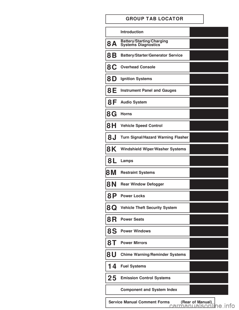
GROUP TAB LOCATOR
Introduction
8ABattery/Starting/Charging
Systems Diagnostics
8BBattery/Starter/Generator Service
8COverhead Console
8DIgnition Systems
8EInstrument Panel and Gauges
8FAudio System
8GHorns
8HVehicle Speed Control
8JTurn Signal/Hazard Warning Flasher
8KWindshield Wiper/Washer Systems
8LLamps
8MRestraint Systems
8NRear Window Defogger
8PPower Locks
8QVehicle Theft Security System
8RPower Seats
8SPower Windows
8TPower Mirrors
8UChime Warning/Reminder Systems
14Fuel Systems
25Emission Control Systems
Component and System Index
Service Manual Comment Forms (Rear of Manual)
Page 31 of 2438
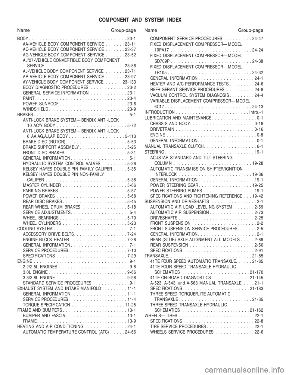
COMPONENT AND SYSTEM INDEX
Name Group-page Name Group-page
BODY ................................... 23-1
AA-VEHICLE BODY COMPONENT SERVICE .......23-11
AC-VEHICLE BODY COMPONENT SERVICE .......23-37
AG-VEHICLE BODY COMPONENT SERVICE .......23-52
AJ/27-VEHICLE CONVERTIBLE BODY COMPONENT SERVICE ............................ 23-86
AJ-VEHICLE BODY COMPONENT SERVICE .......23-71
AP-VEHICLE BODY COMPONENT SERVICE .......23-97
AY-VEHICLE BODY COMPONENT SERVICE .......23-133
BODY DIAGNOSTIC PROCEDURES .............23-2
GENERAL SERVICE INFORMATION .............23-1
PAINT ................................. 23-4
POWER SUNROOF ........................ 23-6
WINDSHIELD ............................ 23-9
BRAKES ..................................5-1
ANTI-LOCK BRAKE SYSTEMÐBENDIX ANTI-LOCK 10 AC/Y BODY ......................... 5-72
ANTI-LOCK BRAKE SYSTEMÐBENDIX ANTI-LOCK 6 AA,AG,AJ,AP BODY .................... 5-113
BRAKE DISC (ROTOR) ...................... 5-53
BRAKE SUPPORT ASSEMBLY .................5-25
FRONT DISC BRAKES ...................... 5-31
GENERAL INFORMATION .....................5-1
HYDRAULIC SYSTEM CONTROL VALVES .........5-26
KELSEY HAYES DOUBLE PIN FAMILY CALIPER .....5-35
KELSEY HAYES DOUBLE PIN NON-FAMILY CALIPER ............................. 5-38
MASTER CYLINDER ....................... 5-66
PARKING BRAKES ........................ 5-57
POWER BRAKES ......................... 5-68
REAR DISC BRAKES ....................... 5-45
REAR WHEEL DRUM BRAKES ................5-18
SERVICE ADJUSTMENTS .....................5-4
WHEEL BEARINGS ........................ 5-70
WHEEL CYLINDERS ....................... 5-23
COOLING SYSTEM ...........................7-1
ACCESSORY DRIVE BELTS ................... 7-24
ENGINE BLOCK HEATER .................... 7-28
GENERAL INFORMATION .....................7-1
SERVICE PROCEDURES ..................... 7-10
SPECIFICATIONS ......................... 7-29
ENGINE ..................................9-1
2.2/2.5L ENGINES .........................9-8
3.0L ENGINE ............................ 9-66
3.3/3.8L ENGINE ......................... 9-98
STANDARD SERVICE PROCEDURES .............9-1
EXHAUST SYSTEM AND INTAKE MANIFOLD .........11-1
GENERAL INFORMATION .................... 11-1
SERVICE PROCEDURES ..................... 11-4
TORQUE SPECIFICATION ................... 11-25
FRAME AND BUMPERS ....................... 13-1
BUMPER AND FASCIA ...................... 13-1
FRAME ................................ 13-9
HEATING AND AIR CONDITIONING ...............24-1
AUTOMATIC TEMPERATURE CONTROL (ATC) .....24-66 COMPONENT SERVICE PROCEDURES
..........24-47
FIXED DISPLACEMENT COMPRESSORÐMODEL 10PA17............................. 24-24
FIXED DISPLACEMENT COMPRESSORÐMODEL SD709P ............................. 24-38
FIXED DISPLACEMENT COMPRESSORÐMODEL TR105 .............................. 24-32
GENERAL INFORMATION .................... 24-1
HEATER AND A/C PERFORMANCE TESTS .........24-6
REFRIGERANT SERVICE PROCEDURES ..........24-8
VACUUM CONTROL SYSTEM DIAGNOSIS .........24-4
VARIABLE DISPLACEMENT COMPRESSORÐMODEL 6C17 ............................... 24-13
INTRODUCTION .......................... Intro.-1
LUBRICATION AND MAINTENANCE ................0-1
CHASSIS AND BODY ....................... 0-19
DRIVETRAIN ............................ 0-16
ENGINE ................................0-8
GENERAL INFORMATION .....................0-1
MANUAL TRANSAXLE CLUTCH ...................6-1
STEERING ................................ 19-1
ACUSTAR STANDARD AND TILT STEERING COLUMN ............................ 19-28
AUTOMATIC TRANSMISSION SHIFTER/IGNITION INTERLOCK .......................... 19-36
GENERAL INFORMATION .................... 19-1
POWER STEERING GEAR ................... 19-25
POWER STEERING PUMPS ..................19-1
SPECIFICATIONS AND TIGHTENING REFERENCE . . . 19-42
SUSPENSION AND DRIVESHAFTS .................2-1
AUTOMATIC AIR LOAD LEVELING SYSTEM ........2-59
AUTOMATIC AIR SUSPENSION ................2-73
DRIVESHAFTS ........................... 2-25
FRONT SUSPENSION .......................2-2
FRONT SUSPENSION SERVICE PROCEDURES .......2-5
GENERAL INFORMATION .....................2-1
REAR (STUB) AXLE ALIGNMENT ALL MODELS .....2-89
REAR SUSPENSION ....................... 2-50
SPECIFICATIONS ......................... 2-91
TRANSAXLE .............................. 21-85
41TE FOUR SPEED AUTOMATIC TRANSAXLE ......21-85
41TE FOUR SPEED TRANSAXLE HYDRAULIC SCHEMATICS ........................ 21-170
41TE ON-BOARD DIAGNOSTICS .............21-145
A-523, A-543, and A-568 MANUAL TRANSAXLE ....21-1
SPECIFICATIONS ........................ 21-183
THREE SPEED TORQUEFLITE AUTOMATIC TRANSAXLE .......................... 21-35
THREE SPEED TRANSAXLE HYDRAULIC SCHEMATICS ........................ 21-162
WHEELSÐTIRES ........................... 22-1
SPECIFICATIONS ......................... 22-8
TIRE SERVICE PROCEDURES .................22-1
WHEELS SERVICE PROCEDURES ..............22-6
Page 33 of 2438
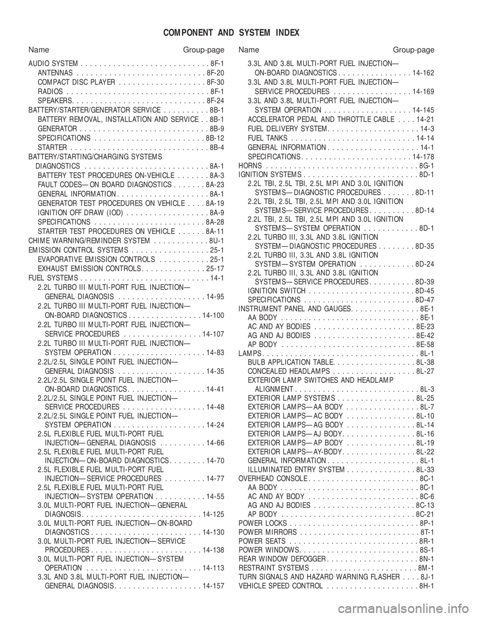
COMPONENT AND SYSTEM INDEX
Name Group-page Name Group-page
AUDIO SYSTEM ............................ 8F-1
ANTENNAS ............................ 8F-20
COMPACT DISC PLAYER ................... 8F-30
RADIOS ............................... 8F-1
SPEAKERS ............................. 8F-24
BATTERY/STARTER/GENERATOR SERVICE ..........8B-1
BATTERY REMOVAL, INSTALLATION AND SERVICE . . 8B-1
GENERATOR ............................ 8B-9
SPECIFICATIONS ........................ 8B-12
STARTER .............................. 8B-4
BATTERY/STARTING/CHARGING SYSTEMS DIAGNOSTICS ........................... 8A-1
BATTERY TEST PROCEDURES ON-VEHICLE .......8A-3
FAULT CODESÐON BOARD DIAGNOSTICS .......8A-23
GENERAL INFORMATION .................... 8A-1
GENERATOR TEST PROCEDURES ON VEHICLE ....8A-19
IGNITION OFF DRAW (IOD) ..................8A-9
SPECIFICATIONS ........................ 8A-28
STARTER TEST PROCEDURES ON VEHICLE ......8A-11
CHIME WARNING/REMINDER SYSTEM ............8U-1
EMISSION CONTROL SYSTEMS .................25-1
EVAPORATIVE EMISSION CONTROLS ...........25-1
EXHAUST EMISSION CONTROLS ..............25-17
FUEL SYSTEMS ............................ 14-1
2.2L TURBO III MULTI-PORT FUEL INJECTIONÐ GENERAL DIAGNOSIS ................... 14-95
2.2L TURBO III MULTI-PORT FUEL INJECTIONÐ ON-BOARD DIAGNOSTICS ................14-100
2.2L TURBO III MULTI-PORT FUEL INJECTIONÐ SERVICE PROCEDURES .................14-107
2.2L TURBO III MULTI-PORT FUEL INJECTIONÐ SYSTEM OPERATION .................... 14-83
2.2L/2.5L SINGLE POINT FUEL INJECTIONÐ GENERAL DIAGNOSIS ................... 14-35
2.2L/2.5L SINGLE POINT FUEL INJECTIONÐ ON-BOARD DIAGNOSTICS .................14-41
2.2L/2.5L SINGLE POINT FUEL INJECTIONÐ SERVICE PROCEDURES .................. 14-48
2.2L/2.5L SINGLE POINT FUEL INJECTIONÐ SYSTEM OPERATION .................... 14-24
2.5L FLEXIBLE FUEL MULTI-PORT FUEL INJECTIONÐGENERAL DIAGNOSIS ..........14-66
2.5L FLEXIBLE FUEL MULTI-PORT FUEL INJECTIONÐON-BOARD DIAGNOSTICS ........14-70
2.5L FLEXIBLE FUEL MULTI-PORT FUEL INJECTIONÐSERVICE PROCEDURES .........14-77
2.5L FLEXIBLE FUEL MULTI-PORT FUEL INJECTIONÐSYSTEM OPERATION ...........14-55
3.0L MULTI-PORT FUEL INJECTIONÐGENERAL DIAGNOSIS .......................... 14-125
3.0L MULTI-PORT FUEL INJECTIONÐON-BOARD DIAGNOSTICS ........................ 14-130
3.0L MULTI-PORT FUEL INJECTIONÐSERVICE PROCEDURES ........................ 14-138
3.0L MULTI-PORT FUEL INJECTIONÐSYSTEM OPERATION ......................... 14-113
3.3L AND 3.8L MULTI-PORT FUEL INJECTIONÐ GENERAL DIAGNOSIS ................... 14-157 3.3L AND 3.8L MULTI-PORT FUEL INJECTIONÐ
ON-BOARD DIAGNOSTICS ................14-162
3.3L AND 3.8L MULTI-PORT FUEL INJECTIONÐ SERVICE PROCEDURES .................14-169
3.3L AND 3.8L MULTI-PORT FUEL INJECTIONÐ SYSTEM OPERATION ................... 14-145
ACCELERATOR PEDAL AND THROTTLE CABLE ....14-21
FUEL DELIVERY SYSTEM .................... 14-3
FUEL TANKS ........................... 14-14
GENERAL INFORMATION .................... 14-1
SPECIFICATIONS ........................ 14-178
HORNS ................................. 8G-1
IGNITION SYSTEMS ......................... 8D-1
2.2L TBI, 2.5L TBI, 2.5L MPI AND 3.0L IGNITION SYSTEMSÐDIAGNOSTIC PROCEDURES .......8D-11
2.2L TBI, 2.5L TBI, 2.5L MPI AND 3.0L IGNITION SYSTEMSÐSERVICE PROCEDURES ..........8D-14
2.2L TBI, 2.5L TBI, 2.5L MPI AND 3.0L IGNITION SYSTEMSÐSYSTEM OPERATION ............8D-1
2.2L TURBO III, 3.3L AND 3.8L IGNITION SYSTEMÐDIAGNOSTIC PROCEDURES ........8D-35
2.2L TURBO III, 3.3L AND 3.8L IGNITION SYSTEMÐSYSTEM OPERATION ............8D-24
2.2L TURBO III, 3.3L AND 3.8L IGNITION SYSTEMSÐSERVICE PROCEDURES ..........8D-39
IGNITION SWITCH ....................... 8D-45
SPECIFICATIONS ........................ 8D-47
INSTRUMENT PANEL AND GAUGES ...............8E-1
AA BODY .............................. 8E-1
AC AND AY BODIES ...................... 8E-23
AG AND AJ BODIES ...................... 8E-42
AP BODY ............................. 8E-58
LAMPS .................................. 8L-1
BULB APPLICATION TABLE ..................8L-38
CONCEALED HEADLAMPS ..................8L-27
EXTERIOR LAMP SWITCHES AND HEADLAMP ALIGNMENT ........................... 8L-3
EXTERIOR LAMP SYSTEMS .................8L-25
EXTERIOR LAMPSÐAA BODY ................8L-7
EXTERIOR LAMPSÐAC BODY ...............8L-10
EXTERIOR LAMPSÐAG BODY ...............8L-14
EXTERIOR LAMPSÐAJ BODY ................8L-16
EXTERIOR LAMPSÐAP BODY ...............8L-19
EXTERIOR LAMPSÐAY-BODY ................8L-22
GENERAL INFORMATION .................... 8L-1
ILLUMINATED ENTRY SYSTEM ...............8L-33
OVERHEAD CONSOLE ........................ 8C-1
AA BODY .............................. 8C-1
AC AND AY BODY ........................ 8C-6
AG AND AJ BODIES ...................... 8C-13
AP BODY ............................. 8C-21
POWER LOCKS ............................ 8P-1
POWER MIRRORS ..........................8T-1
POWER SEATS ............................ 8R-1
POWER WINDOWS .......................... 8S-1
REAR WINDOW DEFOGGER .................... 8N-1
RESTRAINT SYSTEMS ....................... 8M-1
TURN SIGNALS AND HAZARD WARNING FLASHER ....8J-1
VEHICLE SPEED CONTROL .................... 8H-1
Page 44 of 2438
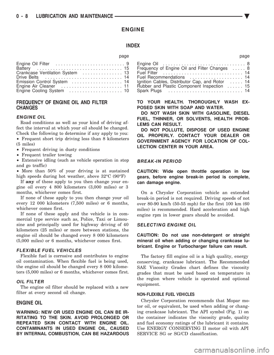
ENGINE INDEX
page page
Engine Oil Filter .......................... 9
Battery ................................ 15
Crankcase Ventilation System ............... 13
Drive Belts ............................. 14
Emission Control System ................... 14
Engine Air Cleaner ....................... 11
Engine Cooling System .................... 10 Engine Oil
............................... 8
Frequency of Engine Oil and Filter Changes ..... 8
Fuel Filter .............................. 14
Fuel Recommendations .................... 14
Ignition Cables, Distributor Cap, and Rotor ..... 14
Rubber and Plastic Component Inspection ...... 15
Spark Plugs ............................ 14
FREQUENCY OF ENGINE OIL AND FILTER
CHANGES
ENGINE OIL
Road conditions as well as your kind of driving af-
fect the interval at which your oil should be changed.
Check the following to determine if any apply to you:
² Frequent short trip driving less than 8 kilometers
(5 miles)
² Frequent driving in dusty conditions
² Frequent trailer towing
² Extensive idling (such as vehicle operation in stop
and go traffic)
² More than 50% of your driving is at sustained
high speeds during hot weather, above 32ÉC (90ÉF) If any of these apply to you then change your en-
gine oil every 4 800 kilometers (3,000 miles) or 3
months, whichever comes first. If none of these apply to you then change your oil
every 12 000 kilometers (7,500 miles) or 6 months,
whichever comes first. If none of these apply and the vehicle is in com-
mercial type service such as, Police, Taxi or Limou-
sine and principally used for highway driving of 40
kilometers (25 miles) or more between stations, the
engine oil should be changed every 8 000 kilometers
(5,000 miles) or 6 months, whichever comes first.
FLEXIBLE FUEL VEHICLES
Flexible fuel is corrosive and contributes to engine
oil contamination. When flexible fuel is being used,
the engine oil should be changed every 8 000 kilome-
ters (5,000 miles) or 6 months, whichever comes first.
OIL FILTER
The engine oil filter should be replaced with a new
filter at every second oil change.
ENGINE OIL
WARNING: NEW OR USED ENGINE OIL CAN BE IR-
RITATING TO THE SKIN. AVOID PROLONGED OR
REPEATED SKIN CONTACT WITH ENGINE OIL.
CONTAMINANTS IN USED ENGINE OIL, CAUSED
BY INTERNAL COMBUSTION, CAN BE HAZARDOUS TO YOUR HEALTH. THOROUGHLY WASH EX-
POSED SKIN WITH SOAP AND WATER. DO NOT WASH SKIN WITH GASOLINE, DIESEL
FUEL, THINNER, OR SOLVENTS, HEALTH PROB-
LEMS CAN RESULT. DO NOT POLLUTE, DISPOSE OF USED ENGINE
OIL PROPERLY. CONTACT YOUR DEALER OR
GOVERNMENT AGENCY FOR LOCATION OF COL-
LECTION CENTER IN YOUR AREA.
BREAK-IN PERIOD
CAUTION: Wide open throttle operation in low
gears, before engine break-in period is complete,
can damage engine.
On a Chrysler Corporation vehicle an extended
break-in period is not required. Driving speeds of not
over 80-90 km/h (50-55 mph) for the first 100 km (60
miles) is recommended. Hard acceleration and high
engine rpm in lower gears should be avoided.
SELECTING ENGINE OIL
CAUTION: Do not use non-detergent or straight
mineral oil when adding or changing crankcase lu-
bricant. Engine or Turbocharger failure can result.
The factory fill engine oil is a high quality, energy
conserving, crankcase lubricant. The Recommended
SAE Viscosity Grades chart defines the viscosity
grades that must be used based on temperature in
the region where vehicle is operated and optional
equipment.
NON-FLEXIBLE FUEL VEHICLES Chrysler Corporation recommends that Mopar mo-
tor oil, or equivalent, be used when adding or chang-
ing crankcase lubricant. The API symbol (Fig. 1) on
the container indicates the viscosity grade, quality
and fuel economy ratings of the lubricant it contains.
Use ENERGY CONSERVING II motor oil with API
SERVICE SG or SG/CD classification.
0 - 8 LUBRICATION AND MAINTENANCE Ä
Page 50 of 2438
PCV SYSTEM TEST
Refer to group 25, Emission Control System for
proper procedures to test PCV system.
FUEL RECOMMENDATIONS
Chrysler Corporation recommends that only fuel pur-
chased from a reputable retailer be used. Use high qual-
ity, unleaded gasoline to provide satisfactory
driveability and highest fuel economy. Gasoline contain-
ing detergent and corrosion control additives are desire-
able. If the engine develops spark knock (audible ping),
poor performance, hard starting or stalling, purchase
fuel from another source. Engine performance can vary
when using different brands of gasoline with the same
octane rating. Occasional light engine spark knock un-
der heavy acceleration, at low speed or when vehicle is
heavily loaded is not harmful. Extended periods of
spark knock under moderate acceleration or at cruising
speed can damage the engine. The cause of excessive
spark knock condition must be diagnosed and corrected.
For diagnostic procedures refer to Group 14, Fuel Sys-
tem and Powertrain Diagnostic Procedures manual.
SELECTING GASOLINE
CAUTION:Do not use fuel containing METHANOL
(methyl or wood alcohol), damage to fuel system
will result. Do not use leaded gasoline, damage to catalytic
converter will result and vehicle will not conform to
emission control standards.
ETHANOL, MTBE OR ETBE BLENDS
All Chrysler Corporation vehicles are designed to
use unleaded gasoline ONLY. Gasohol blends, con-
taining 10% Ethanol (ethyl or grain alcohol) 90% un-
leaded gasoline can be used provided it has adequate
octane rating. Fuel blends containing up to 15% MTBE (Methyl
Tertiary Butyl Ether) and 85% unleaded gasoline can
be used. Fuel blends containing up to 17% ETBE
(Ethyl Tertiary Butyl Ether) and 83% unleaded gas-
oline can also be used. Fuel blended with ethanol, MTBE or ETBE are
also referred to as reformulated or clean air gasoline.
These fuels contribute less emissions to the atmo-
sphere. Chrysler Corporation recommends that
blended fuels be used when available
METHANOL BLENDS Using gasoline blended with methanol can result
in starting and driveability problems. Deterioration
of fuel system components will result. Methanol in-
duced problems are not the responsibility of Chrysler
Corporation and may not be covered by the vehicle
warranty. NON-TURBOCHARGED ENGINES
Use regular unleaded gasoline having a minimum
octane rating of 87 (R+M)/2. Higher octane premium
unleaded gasoline can be used if desired.
2.2L 16 VALVE TURBOCHARGED ENGINE
Use premium unleaded gasoline having a mini-
mum octane rating of 91 (R+M)/2. Gasoline with oc-
tane rating less than 91 (R+M)/2 can be used if
recommended gasoline is not available. Low octane
gasoline will reduce engine performance.
FLEXIBLE FUEL VEHICLES
CAUTION: Do not use 100% methanol, damage to
fuel system can result. Use unleaded regular gasoline having a minimum
octane rating of 87 (R=M)/2 and M85 fuel that is
85% methanol and 15% unleaded gasoline, or a mix-
ture of these two.
FUEL FILTER
The fuel filter requires service only when a fuel
contamination problem is suspected. For proper diag-
nostic and service procedures refer to Group 14, Fuel
System,
IGNITION CABLES, DISTRIBUTOR CAP, AND
ROTOR
Inspect and test ignition cables, distributor cap and
rotor when the spark plugs are replaced. Oil and
grime should be cleaned from the ignition cables and
distributor cap to avoid possible spark plug fouling.
Mopar, Foamy Engine Degreaser, or equivalent is
recommended for cleaning the engine compartment.
For proper service and diagnostic procedures refer to
Group 8D, Ignition System.
SPARK PLUGS
Ignition spark plugs should be replaced at the
mileage interval described in the Lubrication and
Maintenance Schedules. Refer to the General Infor-
mation section of this group. For proper service pro-
cedures refer to Group 8D, Ignition Systems.
DRIVE BELTS
Inspect and adjust drive belts at the interval de-
scribed in the Lubrication and Maintenance Sched-
ules. Refer to General Information section of this
group. For proper inspection and adjustment proce-
dures, see Group 7, Cooling System.
EMISSION CONTROL SYSTEM
Inspect all emission control components and hoses
when other under hood service is performed. Refer to
emission system Vacuum Hose Label located on the
0 - 14 LUBRICATION AND MAINTENANCE Ä
Page 56 of 2438

The power steering pump drive belt should be in-
spected at the time and distance interval described in
the Lubrication and Maintenance Schedules. Refer to
the General Information section of this group.
POWER STEERING FLUID INSPECTION
WARNING: ENGINE MUST NOT BE RUNNING WHEN
INSPECTING POWER STEERING FLUID LEVEL,
PERSONAL INJURY CAN RESULT.
CAUTION: Do not over fill power steering reservoir
when adding fluid, seal damage and leakage can re-
sult.
TO INSPECT FLUID LEVEL:
(1) Position vehicle on a level surface with engine
at normal running temperature. (2) Turn OFF engine and remove ignition key.
(3) Using a wiping cloth, clean oil and dirt residue
from around power steering reservoir cap. (4) Remove reservoir cap or dipstick and wipe off
fluid. (5) Install cap or dipstick.
(6) Remove cap or dipstick. Holding handle or cap
above tip of dipstick, read fluid level (Fig. 4, 5, or 6).
Add fluid if reading is below cold level mark on dip-
stick.
REAR WHEEL BEARINGS
INSPECTION
The rear wheel bearings should be packed with
new lubricant at the distance interval described in the Lubrication and Maintenance Schedules. Refer to
the General Information section of this group. The
bearings should be inspected for contamination and
wear before they are cleaned. Slight discoloration of
bearing rollers and race cup is normal. If metal
Fig. 3 Ball Joint Lubrication
Fig. 4 Power Steering Reservoir DipstickÐ2.2L or 2.5L Engine
Fig. 5 Power Steering Reservoir DipstickÐ3.0L Engine
Fig. 6 Power Steering Reservoir DipstickÐ3.3L or3.8L Engine
0 - 20 LUBRICATION AND MAINTENANCE Ä
Page 58 of 2438

BRAKE RESERVOIR LEVEL INSPECTION
WARNING: DO NOT ALLOW PETROLEUM OR WATER
BASE LIQUIDS TO CONTAMINATE BRAKE FLUID,
SEAL DAMAGE AND BRAKE FAILURE CAN RESULT.
RELIEVE PRESSURE IN ANTI-LOCK BRAKE SYS-
TEM BEFORE ADDING BRAKE FLUID TO RESER-
VOIR. IF NOT, BRAKE FLUID COULD DISCHARGED
FROM THE RESERVOIR POSSIBLY CAUSING PER-
SONAL INJURY.
The brake reservoir level should be inspected when
other under hood service is performed. It is normal
for the reservoir level to drop as disc brake pads
wear. When fluid must be added, use Mopar, Brake
Fluid or equivalent. Use only brake fluid conforming
to DOT 3, Federal, Department of Transportation
specification. To avoid brake fluid contamination, use
fluid from a properly sealed container. On vehicles with anti-lock brakes, depressurize the
system before inspecting fluid level. Turn OFF the
ignition and remove the key. Pump the brake pedal
at least 50 times to relieve the pressure in the sys-
tem.
On all vehicles, if fluid should become low after sev-
eral thousand kilometers (miles), fill the reservoir to
level marks on the side of the reservoir (Fig. 8 or 9).
HEADLAMPS
The headlamps should be inspected for intensity
and aim whenever a problem is suspected. When lug-
gage compartment is heavily loaded, the headlamp
aim should be adjusted to compensate for vehicle
height change. For proper service procedures, refer to
Group 8L, Lamps. DRIVER SUPPLEMENTAL AIRBAG SYSTEM
If the AIRBAG indicator lamp does not light at all,
stays lit or lights momentarily or continuously while
driving, a malfunction may have occurred. Prompt service is required. Refer to Group 8M, Restraint
Systems for proper diagnostic procedures.
BODY LUBRICATION
Body mechanisms and linkages should be inspected,
cleaned and lubricated as required to maintain ease of
operation and to prevent corrosion and wear. Before a component is lubricated, oil, grease and dirt
should be wiped off. If necessary, use solvent to clean
component to be lubricated. After lubrication is com-
plete, wipe off excess grease or oil. During winter season, external lock cylinders should
be lubricated with Mopar, Lock Lubricant or equiva-
lent to ensure proper operation when exposed to water
and ice. To assure proper hood latching component operation,
use engine oil to lubricate the lock, safety catch and
hood hinges when other under hood service is per-
formed. Mopar, Multi-purpose Grease or equivalent
should be applied sparingly to all pivot and slide
contact areas.
USE ENGINE OIL ON:
² Door hingesÐHinge pin and pivot points.
² Hood hingesÐPivot points.
² Luggage compartment lid hingesÐPivot points.
USE MOPAR LUBRIPLATE OR EQUIVALENT ON:
² Door check straps.
² Hood counterbalance springs.
² Luggage compartment lid latches.
² Luggage compartment lid prop rod pivots.
² Ash tray slides.
² Fuel Fill Door latch mechanism.
² Park brake mechanism.
² Front seat tracks.
Fig. 8 Anti-lock Brake Reservoir
Fig. 9 Master Cylinder Brake ReservoirÐExcept
Anti-lock
0 - 22 LUBRICATION AND MAINTENANCE Ä