1993 CHEVROLET PLYMOUTH ACCLAIM ignition
[x] Cancel search: ignitionPage 2384 of 2438

(4) If pin #13 shows continuity, repair circuit C02
and retest. (5) If no continuity is shown, replace the ATC con-
trol and retest.
DIAGNOSTIC TROUBLE CODE 7ÐBLOWER DRIVE SIGNAL NOT HIGH
First check the 4-way connector to the power
module for correct installation (1) With the ignition ON, check for ignition volt-
age to the power module pin #1 from the ATC con-
trol. If ignition is present at the power module,
proceed to step 3. If not proceed to step 2. (2) With the 21-way connector still connected and
the ignition ON, check for power module ignition
feed at the control pin #12. If ignition is not present,
replace the control. If ignition voltage is present, re-
pair the open in the wire between the control pin
#12 and power module pin #1. Retest system. (3) Turn ignition OFF and disconnect the 21-way
connector. Measure the resistance between pins #2
and #12. The resistance should read between 2,600
and 2,800 ohms. If correct, replace the ATC control.
If not correct, proceed to step 4. (4) Remove the 4-way connector from the power
module. Check for continuity between the ATC con-
trol pin #2 and power module pin #2. If no continu-
ity is shown, repair the wire for an open. If
continuity is shown, replace the power module and
retest.
DIAGNOSTIC TROUBLE CODE 8ÐA/D CONVERTOR INTERNAL FAILURE
Diagnostics will indicate a Diagnostic Trouble Code
8 if the internal reference voltage of the A/D Conver-
tor is not correct. This Diagnostic Trouble Code is
not serviceable. If a Diagnostic Trouble Code 8 oc-
curs, the computer control head must be replaced.
DIAGNOSTIC TROUBLE CODE 9ÐSUN LOAD SENSOR FAILURE
(1) Unplug the 21-way connector from the control
and check pin #19 for continuity to chassis ground.
If continuity is present, repair the wire shorted to
ground. If no continuity is present, proceed to step 2. (2) Plug the 21-way connector back in. Remove pin
#19 from the 21 way connector and run diagnostics
again. If Diagnostic Trouble Code 9 is still present,
replace the control. If code 9 is not present, replace
the sun sensor.
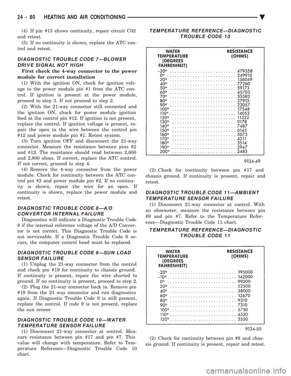
DIAGNOSTIC TROUBLE CODE 10ÐWATER TEMPERATURE SENSOR FAILURE
(1) Disconnect 21-way connector at control. Mea-
sure resistance between pin #17 and pin #7. This
value will change with temperature. Refer to Tem-
perature ReferenceÐDiagnostic Trouble Code 10
chart. (2) Check for continuity between pin #17 and
chassis ground. If continuity is present, repair and
retest.
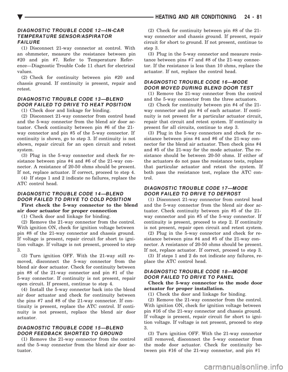
DIAGNOSTIC TROUBLE CODE 11ÐAMBIENT TEMPERATURE SENSOR FAILURE
(1) Disconnect 21-way connector at control. With
an ohmmeter, measure the resistance between pin
#9 and pin #7. Refer to the Temperature Refer-
enceÐDiagnostic Trouble Code 11 chart.
(2) Check for continuity between pin #9 and chas-
sis ground. If continuity is present, repair and retest.
TEMPERATURE REFERENCEÐDIAGNOSTIC TROUBLE CODE 10
TEMPERATURE REFERENCEÐDIAGNOSTICTROUBLE CODE 11
24 - 80 HEATING AND AIR CONDITIONING Ä
Page 2385 of 2438

DIAGNOSTIC TROUBLE CODE 12ÐIN-CAR TEMPERATURE SENSOR/ASPIRATORFAILURE
(1) Disconnect 21-way connector at control. With
an ohmmeter, measure the resistance between pin
#20 and pin #7. Refer to Temperature Refer-
enceÐDiagnostic Trouble Code 11 chart for electrical
values. (2) Check for continuity between pin #20 and
chassis ground. If continuity is present, repair and
retest.
DIAGNOSTIC TROUBLE CODE 13ÐBLEND DOOR FAILED TO DRIVE TO HEAT POSITION
(1) Check door and linkage for binding.
(2) Disconnect 21-way connector from control head
and the 5-way connector from the blend air door ac-
tuator. Check continuity between pin #6 of the 21-
way connector and pin #5 of the 5-way connector. If
continuity is shown, go to step 3. If continuity is not
shown, repair circuit for an open circuit and retest
system. (3) Plug in the 5-way connector and check for re-
sistance between pins #4 and #6 of the 21-way con-
nector. A resistance of 20-50 ohms should be present.
If not, replace actuator. If correct, proceed to step 4. (4) If steps 1 and 2 indicate no failures, replace the
ATC control head.
DIAGNOSTIC TROUBLE CODE 14ÐBLEND DOOR FAILED TO DRIVE TO COLD POSITION
First check the 5-way connector to the blend
air door actuator for proper connection (1) Check door and linkage for binding.
(2) Remove the 21-way connector from the control.
With ignition ON, check for ignition voltage between
pin #8 of the 21-way connector and chassis ground.
If voltage is present, repair circuit for short to igni-
tion voltage. If voltage is not present, proceed to step
3. (3) Turn ignition OFF. With the 21-way still re-
moved, disconnect the 5-way connector from the
blend air door actuator. Check for continuity between
pin #8 of the 21-way connector and pin #1 of the
5-way connector. If continuity is not present, repair
open circuit. If present, continue to step 4. (4) Install the 5-way connector back into the blend
air door actuator and check for continuity between
the pins #7 and #8 of the 21-way connector. If con-
tinuity is present, replace the ATC control. If conti-
nuity is not present, replace the blend air door
actuator.
DIAGNOSTIC TROUBLE CODE 15ÐBLEND DOOR FEEDBACK SHORTED TO GROUND
(1) Remove the 21-way connector from the control
and the 5-way connector from the blend air door ac-
tuator. (2) Check for continuity between pin #8 of the 21-
way connector and chassis ground. If present, repair
circuit for short to ground. If not present, continue to
step 3. (3) Plug in the 5-way connector and measure resis-
tance between pins #7 and #8 of the 21-way connec-
tor. If the resistance is less than 10 ohms, replace the
actuator. If not, replace the control head.
DIAGNOSTIC TROUBLE CODE 16ÐMODE DOOR MOVED DURING BLEND DOOR TEST
(1) Remove the 21-way connector from the control
and the 5-way connector from the three actuators. (2) Check for continuity between pin #4 of the 21-
way connector and pin #4 of each actuator. If conti-
nuity is not present for a particular actuator circuit,
repair that circuit and retest system. If continuity is
present for all circuits, continue to step 3. (3) Plug in the 5-way connectors and check for re-
sistance between pins #4 and #6 of the 21-way con-
nector for the blend air actuator. Then check pins #4
and #5 of the 21-way for the mode actuator. The re-
sistance should be between 20-50 ohms. If either of
the actuators do not pass the resistance tests, replace
that particular actuator and retest the system. If
both pass the resistance test, replace the ATC con-
trol.
DIAGNOSTIC TROUBLE CODE 17ÐMODE DOOR FAILED TO DRIVE TO DEFROST
(1) Disconnect 21-way connector from control head
and the 5-way connector from the blend air door ac-
tuator. Check continuity between pin #5 of the 21-
way connector and pin #5 of the 5-way connector. If
continuity is present, proceed to step 2. If continuity
is not present, repair open circuit and retest system. (2) Plug in the 5-way connector and check for re-
sistance between pins #4 and #5 of the 21-way con-
nector. A resistance of 20-50 ohms should be present.
If not, replace actuator. If correct, proceed to step 3. (3) If steps 1 and 2 do not indicate any failures, re-
place the ATC control head.
DIAGNOSTIC TROUBLE CODE 18ÐMODE DOOR FAILED TO DRIVE TO PANEL
Check the 5-way connector to the mode door
actuator for proper installation. (1) Check the door and linkage for binding.
(2) Remove the 21-way connector from the control.
With ignition ON, check for ignition voltage between
pin #16 of the 21-way connector and chassis ground.
If voltage is present, repair circuit for short to igni-
tion voltage. If voltage is not present, proceed to step
3. (3) Turn ignition OFF. With the 21-way connector
still removed, disconnect the 5-way connector from
the mode door actuator. Check for continuity be-
tween pin #16 of the 21-way connector, and pin #1
Ä HEATING AND AIR CONDITIONING 24 - 81