1993 CHEVROLET PLYMOUTH ACCLAIM ignition
[x] Cancel search: ignitionPage 1897 of 2438
3.3L AND 3.8L MULTI-PORT FUEL INJECTIONÐGENERAL DIAGNOSIS INDEX
page page
Fuel System Diagram .................... 157 Visual Inspection........................ 157
FUEL SYSTEM DIAGRAM
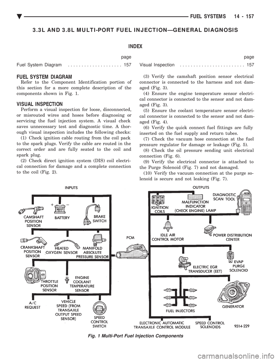
Refer to the Component Identification portion of
this section for a more complete description of the
components shown in Fig. 1.
VISUAL INSPECTION
Perform a visual inspection for loose, disconnected,
or misrouted wires and hoses before diagnosing or
servicing the fuel injection system. A visual check
saves unnecessary test and diagnostic time. A thor-
ough visual inspection includes the following checks: (1) Check ignition cable routing from the coil pack
to the spark plugs. Verify the cable are routed in the
correct order and are fully seated to the coil and
spark plug. (2) Check direct ignition system (DIS) coil electri-
cal connection for damage and a complete connection
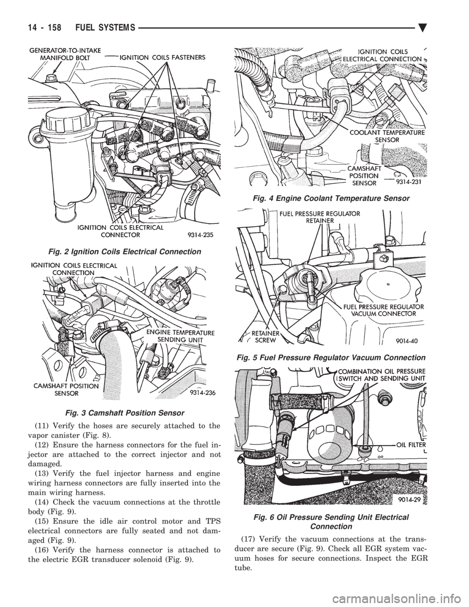
to the coil (Fig. 2). (3) Verify the camshaft position sensor electrical
connector is connected to the harness and not dam-
aged (Fig. 3). (4) Ensure the engine temperature sensor electri-
cal connector is connected to the sensor and not dam-
aged (Fig. 3). (5) Ensure the coolant temperature sensor electri-
cal connector is connected to the sensor and not dam-
aged (Fig. 4). (6) Verify the quick connect fuel fittings are fully
inserted on the fuel supply and return tubes. (7) Check the vacuum hose connection at the fuel
pressure regulator for damage or leakage (Fig. 5). (8) Check the oil pressure sending unit electrical
connection (Fig. 6). (9) Verify the electrical connector is attached to
the Purge Solenoid (Fig. 7) and not damaged. (10) Verify the vacuum connection at the purge so-
lenoid is secure and not leaking (Fig. 7).
Fig. 1 Multi-Port Fuel Injection Components
Ä FUEL SYSTEMS 14 - 157
Page 1898 of 2438
(11) Verify the hoses are securely attached to the
vapor canister (Fig. 8). (12) Ensure the harness connectors for the fuel in-
jector are attached to the correct injector and not
damaged. (13) Verify the fuel injector harness and engine
wiring harness connectors are fully inserted into the
main wiring harness. (14) Check the vacuum connections at the throttle
body (Fig. 9). (15) Ensure the idle air control motor and TPS
electrical connectors are fully seated and not dam-
aged (Fig. 9). (16) Verify the harness connector is attached to
the electric EGR transducer solenoid (Fig. 9). (17) Verify the vacuum connections at the trans-
ducer are secure (Fig. 9). Check all EGR system vac-
uum hoses for secure connections. Inspect the EGR
tube.
Fig. 2 Ignition Coils Electrical Connection
Fig. 3 Camshaft Position Sensor
Fig. 4 Engine Coolant Temperature Sensor
Fig. 5 Fuel Pressure Regulator Vacuum Connection
Fig. 6 Oil Pressure Sending Unit Electrical Connection
14 - 158 FUEL SYSTEMS Ä
Page 1902 of 2438
3.3L AND 3.8L MULTI-PORT FUEL INJECTIONÐON-BOARD DIAGNOSTICS INDEX
page page
60-Way Pcm Wiring Connector ............. 167
Circuit Actuation Test Mode ................ 166
Diagnostic Trouble Code Description ......... 163
General Information ...................... 162
High and Low Limits ..................... 163
Monitored Circuits ....................... 162 Non-Monitored Circuits
................... 162
State Display Test Mode .................. 163
System Tests .......................... 163
Throttle Body Minimum Air Flow Check Procedure ............................ 166
GENERAL INFORMATION
The powertrain control module (PCM) has been
programmed to monitor many different circuits of the
fuel injection system. If a problem is sensed with a
monitored circuit often enough to indicate an actual
problem, the PCM stores a fault. If the problem is re-
paired or ceases to exist, the PCM cancels the Diag-
nostic trouble code after 51 vehicle key on/off cycles. Certain criteria must be met for a diagnostic trou-
ble code to be entered into the PCM memory. The
criteria may be a specific range of engine RPM, en-
gine temperature, and/or input voltage to the PCM. It is possible a diagnostic trouble code for a moni-
tored circuit may not be entered into memory even
though a malfunction has occurred. This may happen
because one of the diagnostic trouble code criteria for
the circuit has not been met. For example, assume
one of the diagnostic trouble code criteria for a sen-
sor circuit is the engine must be operating between
750 and 2000 RPM. If the sensor output circuit
shorts to ground when engine RPM is above 2400
RPM (resulting i n a 0 volt input to the PCM) a diag-
nostic trouble code will not be entered into memory.
This is because the condition does not occur within
the specified RPM range. There are several operating conditions that the
PCM does not monitor and set diagnostic trouble
codes for. Refer to Monitored Circuits and Non-Mon-
itored Circuits in this section. Stored diagnostic trouble codes can be displayed ei-
ther by cycling the ignition key On - Off - On - Off -
On, or through use of the DRBII scan tool. The
DRBII scan tool connects to the data link connector
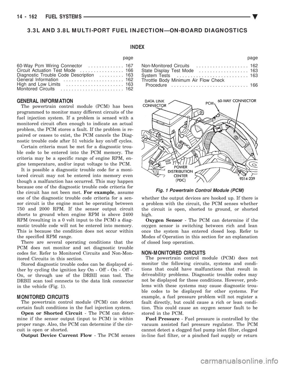
in the vehicle (Fig. 1).
MONITORED CIRCUITS
The powertrain control module (PCM) can detect
certain fault conditions in the fuel injection system. Open or Shorted Circuit - The PCM can deter-
mine if the sensor output (input to PCM) is within
proper range. Also, the PCM can determine if the cir-
cuit is open or shorted. Output Device Current Flow - The PCM senses whether the output devices are hooked up. If there is
a problem with the circuit, the PCM senses whether
the circuit is open, shorted to ground, or shorted
high. Oxygen Sensor - The PCM can determine if the
oxygen sensor is switching between rich and lean
once the system has entered closed loop. Refer to
Modes of Operation in this section for an explanation
of closed loop operation.
NON-MONITORED CIRCUITS
The powertrain control module (PCM) does not
monitor the following circuits, systems and condi-
tions that could have malfunctions that result in
driveability problems. Diagnostic trouble codes may
not be displayed for these conditions. However, prob-
lems with these systems may cause diagnostic trou-
ble codes to be displayed for other systems. For
example, a fuel pressure problem will not register a
fault directly, but could cause a rich or lean condi-
tion. This could cause an oxygen sensor fault to be
stored in the PCM. Fuel Pressure - Fuel pressure is controlled by the
vacuum assisted fuel pressure regulator. The PCM
cannot detect a clogged fuel pump inlet filter, clogged
in-line fuel filter, or a pinched fuel supply or return
Fig. 1 Powertrain Control Module (PCM)
14 - 162 FUEL SYSTEMS Ä
Page 1903 of 2438
line. However, these could result in a rich or lean
condition causing an oxygen sensor fault to be stored in
the PCM. Secondary Ignition Circuit - The PCM cannot
detect an inoperative ignition coil, fouled or worn spark
plugs, ignition cross firing, or open spark plug cables. Engine Timing - The PCM cannot detect an incor-
rectly indexed timing chain, camshaft sprocket and
crankshaft sprocket. However, these could result in a
rich or lean condition causing an oxygen sensor fault to
be stored in the PCM. Cylinder Compression - The PCM cannot detect
uneven, low, or high engine cylinder compression. Exhaust System - The PCM cannot detect a
plugged, restricted or leaking exhaust system. Fuel Injector Malfunctions - The PCM cannot
determine if a fuel injector is clogged, the needle is
sticking or the wrong injector is installed. However,
these could result in a rich or lean condition causing an
oxygen sensor fault to be stored in the PCM. Excessive Oil Consumption - Although the PCM
monitors exhaust stream oxygen content when the
system is in closed loop, it cannot determine excessive
oil consumption. Throttle Body Air Flow - The PCM cannot detect a
clogged or restricted air cleaner inlet or filter element. Evaporative System - The PCM will not detect a
restricted, plugged or loaded evaporative purge canis-
ter. Vacuum Assist - Leaks or restrictions in the
vacuum circuits of vacuum assisted engine control
system devices are not monitored by the PCM. How-
ever, these could result in a MAP sensor fault being
stored in the PCM. PCM System Ground - The PCM cannot determine
a poor system ground. However, a diagnostic trouble
code may be generated as a result of this condition. PCM Connector Engagement - The PCM cannot
determine spread or damaged connector pins. How-
ever, a diagnostic trouble code may be generated as a
result of this condition.
HIGH AND LOW LIMITS
The powertrain control module (PCM) compares in-
put signal voltages from each input device with estab-
lished high and low limits for the device. If the input
voltage is not within limits and other diagnostic
trouble code criteria are met, a diagnostic trouble code
will be stored in memory. Other diagnostic trouble code
criteria might include engine RPM limits or input
voltages from other sensors or switches that must be
present before a fault condition can be verified.
DIAGNOSTIC TROUBLE CODE DESCRIPTION
A diagnostic trouble code indicates that the power-
train control module (PCM) has recognized an abnor- mal condition in the system. Diagnostic trouble codes
can be obtained from the malfunction indicator lamp
(Check Engine lamp on the instrument panel) or from
the DRBII scan tool. Diagnostic trouble codes indicate
the results of a failure but do not identify the failed
component directly.
SYSTEM TESTS
WARNING: APPLY PARKING BRAKE AND/OR BLOCK
WHEELS BEFORE PERFORMING ANY TEST ON AN
OPERATING ENGINE.
OBTAINING DIAGNOSTIC TROUBLE CODES
(1) Connect the DRBII scan tool to the data link
connector located in the engine compartment near the
driver side strut tower (Fig. 1). (2) Start the engine if possible, cycle the transaxle
selector and the A/Cswitch if applicable. Shut off the
engine. (3) Turn the ignition switch on, access Read Fault
Screen. Record all the fault messages shown on the
DRBII scan tool. Observe the malfunction indicator
lamp (check engine lamp on the instrument panel). The
lamp should light for 2 seconds then go out (bulb
check). Diagnostic trouble code erasure; access erase
diagnostic trouble code data
STATE DISPLAY TEST MODE
The switch inputs used by the powertrain control
module (PCM) have only two recognized states, HIGH
and LOW. For this reason, the PCM cannot recognize
the difference between a selected switch position ver-
sus an open circuit, a short circuit, or a defective
switch. If the change is displayed, it can be assumed
that the entire switch circuit to the PCM is functional.
From the state display screen access either State
Display Inputs and Outputs or State Display Sensors.
STATE DISPLAY INPUTS AND OUTPUTS
Connect the DRBII scan tool to the vehicle and access
the State Display screen. Then access Inputs and
Outputs. The following is a list of the engine control
system functions accessible through the Inputs and
Outputs screen. Park/Neutral Switch
Speed Control Resume
Brake Switch
Speed Control On/Off
Speed Control Set
A/C Switch Sense
S/C Vent Solenoid
Ä FUEL SYSTEMS 14 - 163
Page 1906 of 2438
S/C Vacuum Solenoid
A/C Clutch Relay
EGR Solenoid
Auto Shutdown Relay
Radiator Fan Relay
Purge Solenoid
Malfunction Indicator Lamp (Check Engine Lamp)
STATE DISPLAY SENSORS
Connect the DRBII scan tool to the vehicle and ac-
cess the State Display screen. Then access Sensor
Display. The following is a list of the engine control
system functions accessible through the Sensor Dis-
play screen. Oxygen Sensor Signal
Engine Coolant Temperature
Engine Coolant Temp Sensor
Throttle Position
Minimum Throttle
Battery Voltage
MAP Sensor Reading
Idle Air Control Motor Position
Adaptive Fuel Factor
Barometric Pressure
Min Airflow Idle Spd (speed)
Engine Speed
DIS Sensor Status
Fault #1 Key-On Info
Module Spark Advance
Speed Control Target
Fault #2 Key-on Info
Fault #3 Key-on Info
Speed Control Status
Speed Control Switch Voltage
Charging System Goal
Theft Alarm Status
Map Sensor Voltage
Vehicle Speed
Oxygen Sensor State
MAP Gauge Reading
Throttle Opening (percentage)
Total Spark Advance
CIRCUIT ACTUATION TEST MODE
The circuit actuation test mode checks for proper
operation of output circuits or devices which the pow-
ertrain control module (PCM) cannot internally rec-
ognize. The PCM can attempt to activate these
outputs and allow an observer to verify proper oper-
ation. Most of the tests provide an audible or visual
indication of device operation (click of relay contacts,
spray fuel, etc.). Except for intermittent conditions, if
a device functions properly during testing, assume
the device, its associated wiring, and driver circuit
working correctly.
OBTAINING CIRCUIT ACTUATION TEST
Connect the DRBII scan tool to the vehicle and ac-
cess the Actuators screen. The following is a list of
the engine control system functions accessible
through Actuators screens. Stop All Tests
Ignition Coil #1
Ignition Coil #2
Ignition Coil #3
Fuel Injector #1
Fuel Injector #2
Fuel Injector #3
Fuel Injector #4
Fuel Injector #5
Fuel Injector #6
Idle Air Control Motor Open/Close
Radiator Fan Relay
A/C Clutch Relay
Auto Shutdown Relay
EVAP Purge Solenoid
S/C Servo Solenoids
Generator Field
EGR Solenoid
All Solenoids/Relays
ASD Fuel System Test
Speed Control Vacuum Solenoid
Speed Control Vent Solenoid
THROTTLE BODY MINIMUM AIR FLOW CHECK
PROCEDURE
(1) Warm engine in Park or Neutral until the cool-
ing fan has cycled on and off at least once. (2) Ensure that all accessories are off.
(3) Shut off engine.
(4) Disconnect the PCV valve hose from the intake
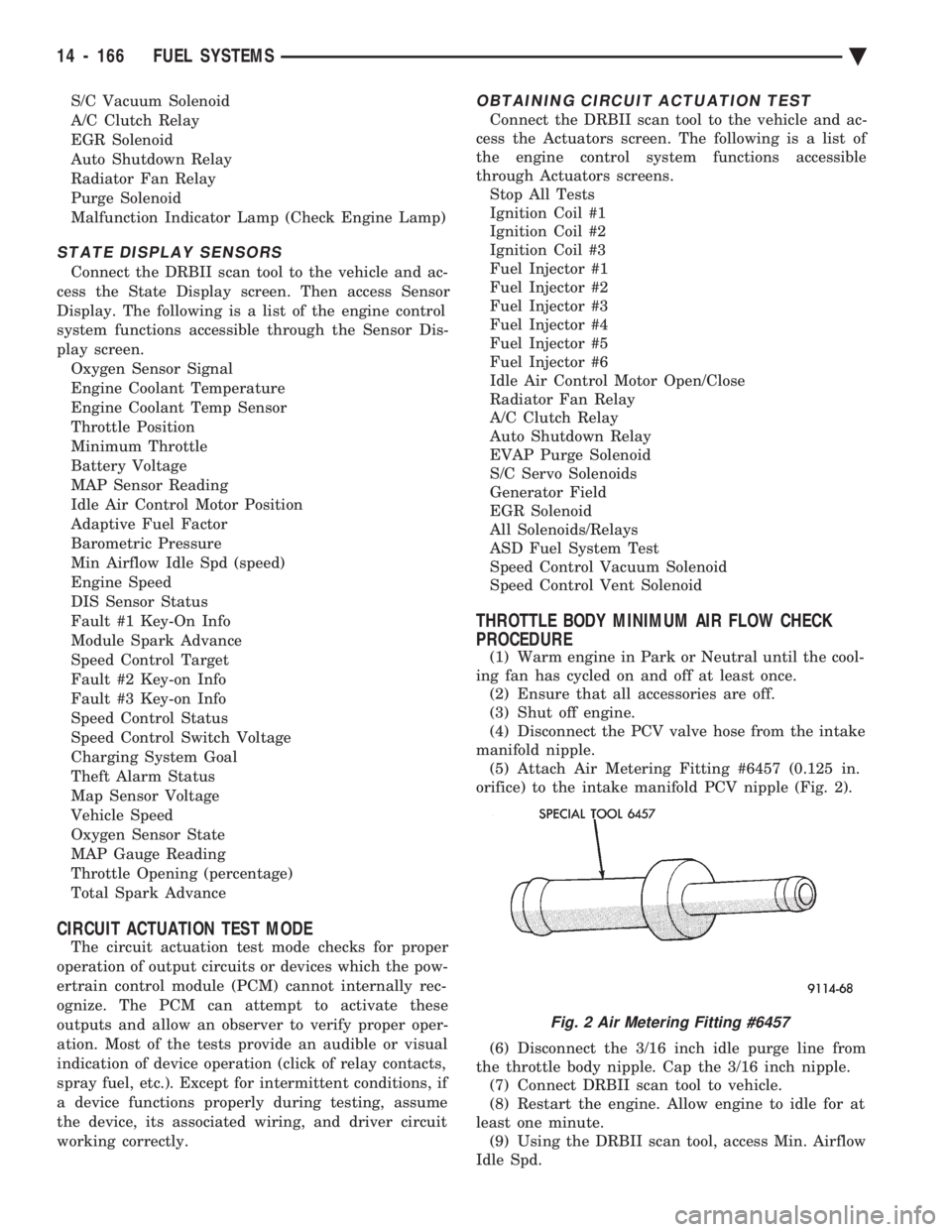
manifold nipple. (5) Attach Air Metering Fitting #6457 (0.125 in.
orifice) to the intake manifold PCV nipple (Fig. 2).
(6) Disconnect the 3/16 inch idle purge line from
the throttle body nipple. Cap the 3/16 inch nipple. (7) Connect DRBII scan tool to vehicle.
(8) Restart the engine. Allow engine to idle for at
least one minute. (9) Using the DRBII scan tool, access Min. Airflow
Idle Spd.
Fig. 2 Air Metering Fitting #6457
14 - 166 FUEL SYSTEMS Ä
Page 1912 of 2438
(12) Remove the fuel hose quick connect fittings
from the chassis tubes. Refer to Fuel Hoses, Clamps
and Quick Connect Fittings in the Fuel Delivery
Section of this Group. Place a shop towel under the
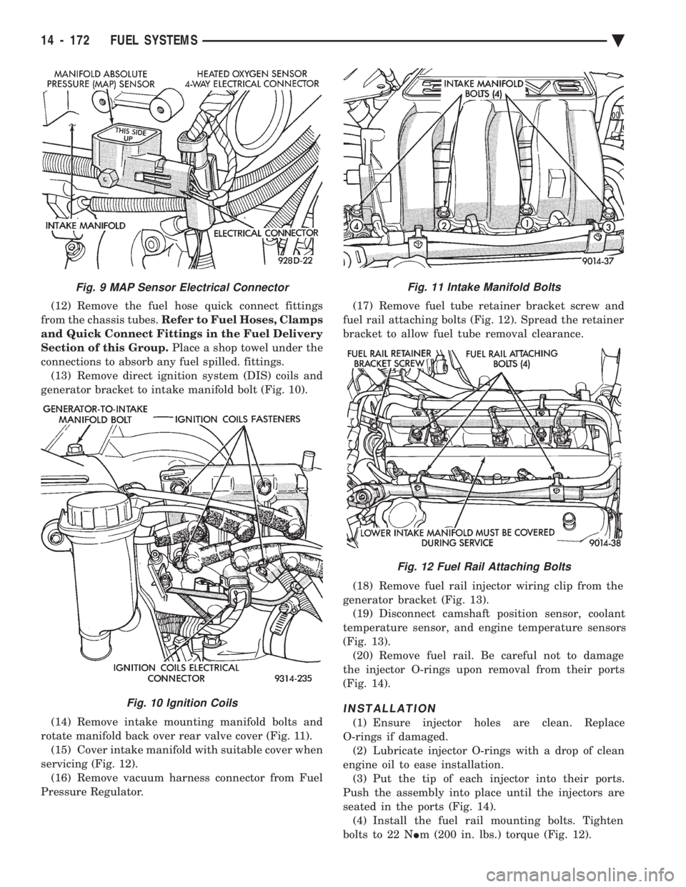
connections to absorb any fuel spilled. fittings. (13) Remove direct ignition system (DIS) coils and
generator bracket to intake manifold bolt (Fig. 10).
(14) Remove intake mounting manifold bolts and
rotate manifold back over rear valve cover (Fig. 11). (15) Cover intake manifold with suitable cover when
servicing (Fig. 12). (16) Remove vacuum harness connector from Fuel
Pressure Regulator. (17) Remove fuel tube retainer bracket screw and
fuel rail attaching bolts (Fig. 12). Spread the retainer
bracket to allow fuel tube removal clearance.
(18) Remove fuel rail injector wiring clip from the
generator bracket (Fig. 13). (19) Disconnect camshaft position sensor, coolant
temperature sensor, and engine temperature sensors
(Fig. 13). (20) Remove fuel rail. Be careful not to damage
the injector O-rings upon removal from their ports
(Fig. 14).
INSTALLATION
(1) Ensure injector holes are clean. Replace
O-rings if damaged. (2) Lubricate injector O-rings with a drop of clean
engine oil to ease installation. (3) Put the tip of each injector into their ports.
Push the assembly into place until the injectors are
seated in the ports (Fig. 14). (4) Install the fuel rail mounting bolts. Tighten
bolts to 22 N Im (200 in. lbs.) torque (Fig. 12).
Fig. 11 Intake Manifold Bolts
Fig. 12 Fuel Rail Attaching Bolts
Fig. 9 MAP Sensor Electrical Connector
Fig. 10 Ignition Coils
14 - 172 FUEL SYSTEMS Ä
Page 1913 of 2438
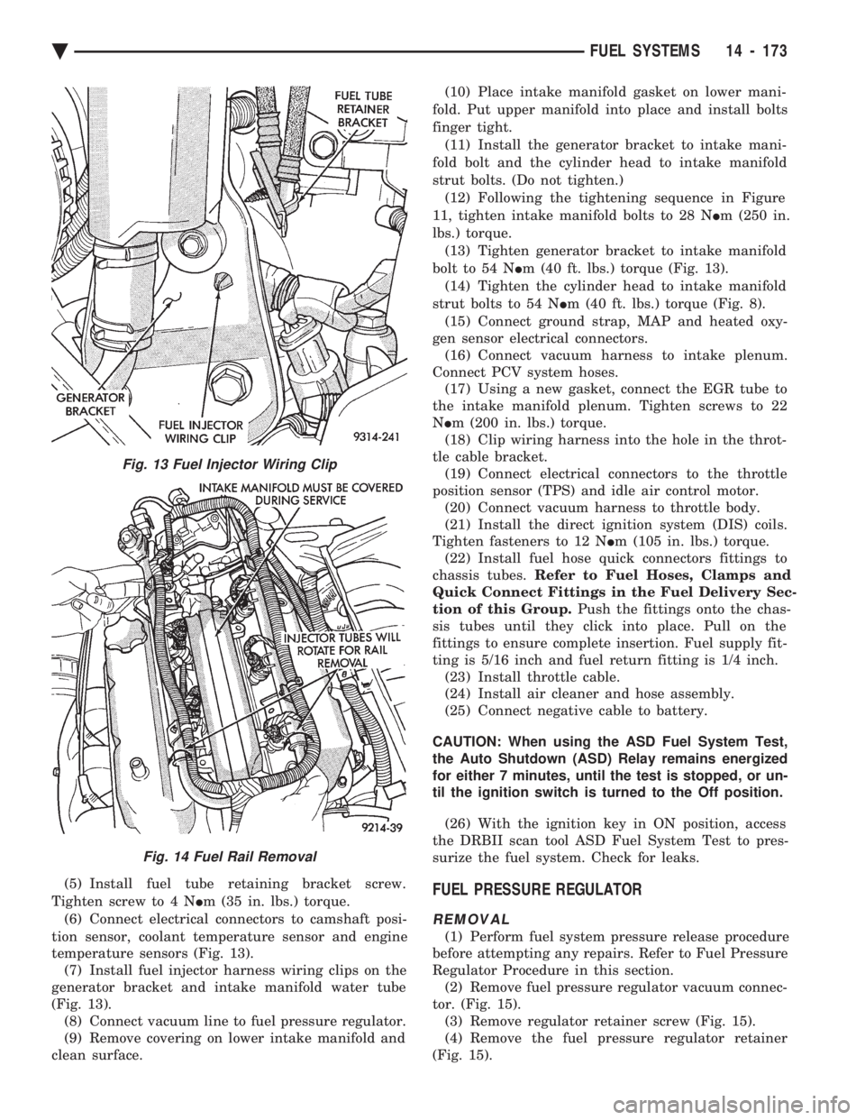
(5) Install fuel tube retaining bracket screw.
Tighten screw to 4 N Im (35 in. lbs.) torque.
(6) Connect electrical connectors to camshaft posi-
tion sensor, coolant temperature sensor and engine
temperature sensors (Fig. 13). (7) Install fuel injector harness wiring clips on the
generator bracket and intake manifold water tube
(Fig. 13). (8) Connect vacuum line to fuel pressure regulator.
(9) Remove covering on lower intake manifold and
clean surface. (10) Place intake manifold gasket on lower mani-
fold. Put upper manifold into place and install bolts
finger tight. (11) Install the generator bracket to intake mani-
fold bolt and the cylinder head to intake manifold
strut bolts. (Do not tighten.) (12) Following the tightening sequence in Figure
11, tighten intake manifold bolts to 28 N Im (250 in.
lbs.) torque. (13) Tighten generator bracket to intake manifold
bolt to 54 N Im (40 ft. lbs.) torque (Fig. 13).
(14) Tighten the cylinder head to intake manifold
strut bolts to 54 N Im (40 ft. lbs.) torque (Fig. 8).
(15) Connect ground strap, MAP and heated oxy-
gen sensor electrical connectors. (16) Connect vacuum harness to intake plenum.
Connect PCV system hoses. (17) Using a new gasket, connect the EGR tube to
the intake manifold plenum. Tighten screws to 22
N Im (200 in. lbs.) torque.
(18) Clip wiring harness into the hole in the throt-
tle cable bracket. (19) Connect electrical connectors to the throttle
position sensor (TPS) and idle air control motor. (20) Connect vacuum harness to throttle body.
(21) Install the direct ignition system (DIS) coils.
Tighten fasteners to 12 N Im (105 in. lbs.) torque.
(22) Install fuel hose quick connectors fittings to
chassis tubes. Refer to Fuel Hoses, Clamps and
Quick Connect Fittings in the Fuel Delivery Sec-
tion of this Group. Push the fittings onto the chas-
sis tubes until they click into place. Pull on the
fittings to ensure complete insertion. Fuel supply fit-
ting is 5/16 inch and fuel return fitting is 1/4 inch. (23) Install throttle cable.
(24) Install air cleaner and hose assembly.
(25) Connect negative cable to battery.
CAUTION: When using the ASD Fuel System Test,
the Auto Shutdown (ASD) Relay remains energized
for either 7 minutes, until the test is stopped, or un-
til the ignition switch is turned to the Off position.
(26) With the ignition key in ON position, access
the DRBII scan tool ASD Fuel System Test to pres-
surize the fuel system. Check for leaks.FUEL PRESSURE REGULATOR
REMOVAL
(1) Perform fuel system pressure release procedure
before attempting any repairs. Refer to Fuel Pressure
Regulator Procedure in this section. (2) Remove fuel pressure regulator vacuum connec-
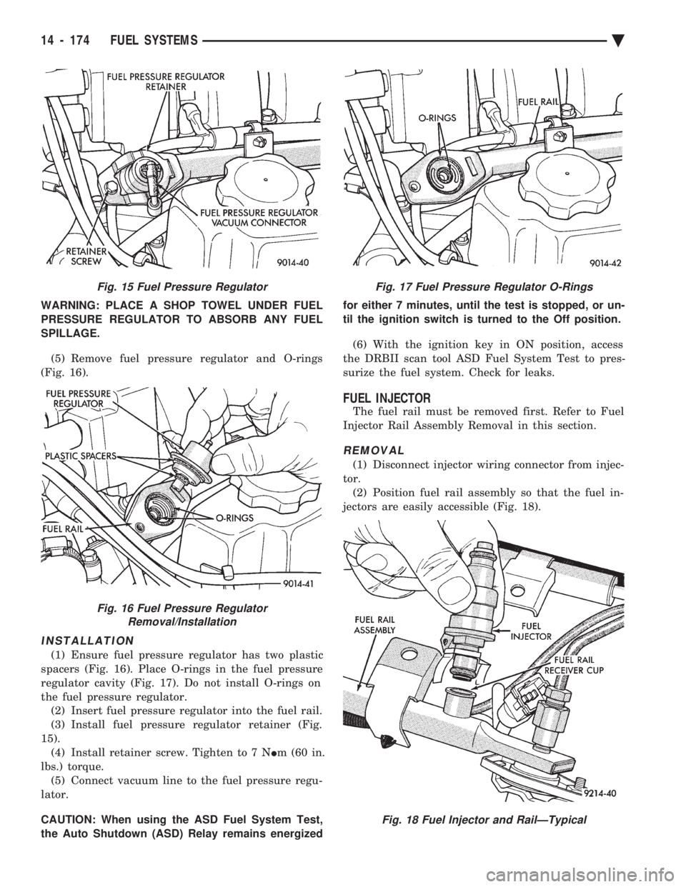
tor. (Fig. 15). (3) Remove regulator retainer screw (Fig. 15).
(4) Remove the fuel pressure regulator retainer
(Fig. 15).
Fig. 13 Fuel Injector Wiring Clip
Fig. 14 Fuel Rail Removal
Ä FUEL SYSTEMS 14 - 173
Page 1914 of 2438
WARNING: PLACE A SHOP TOWEL UNDER FUEL
PRESSURE REGULATOR TO ABSORB ANY FUEL
SPILLAGE.
(5) Remove fuel pressure regulator and O-rings
(Fig. 16).
INSTALLATION
(1) Ensure fuel pressure regulator has two plastic
spacers (Fig. 16). Place O-rings in the fuel pressure
regulator cavity (Fig. 17). Do not install O-rings on
the fuel pressure regulator. (2) Insert fuel pressure regulator into the fuel rail.
(3) Install fuel pressure regulator retainer (Fig.
15). (4) Install retainer screw. Tighten to 7 N Im (60 in.
lbs.) torque. (5) Connect vacuum line to the fuel pressure regu-
lator.
CAUTION: When using the ASD Fuel System Test,
the Auto Shutdown (ASD) Relay remains energized for either 7 minutes, until the test is stopped, or un-
til the ignition switch is turned to the Off position.
(6) With the ignition key in ON position, access
the DRBII scan tool ASD Fuel System Test to pres-
surize the fuel system. Check for leaks.
FUEL INJECTOR
The fuel rail must be removed first. Refer to Fuel
Injector Rail Assembly Removal in this section.
REMOVAL
(1) Disconnect injector wiring connector from injec-
tor. (2) Position fuel rail assembly so that the fuel in-
jectors are easily accessible (Fig. 18).
Fig. 15 Fuel Pressure Regulator
Fig. 16 Fuel Pressure Regulator Removal/Installation
Fig. 17 Fuel Pressure Regulator O-Rings
Fig. 18 Fuel Injector and RailÐTypical
14 - 174 FUEL SYSTEMS Ä