1993 CHEVROLET PLYMOUTH ACCLAIM park assist
[x] Cancel search: park assistPage 225 of 2438

ABS EQUIPPED VEHICLE PERFORMANCE
Anti-Lock Brakes provide the driver with some
steering control during hard braking. However there
are conditions where the system does not provide any
benefit. In particular, hydroplaning is still possible
when the tires ride on a film of water. Hydroplaning
results in the vehicle tires leaving the road surface
rendering the vehicle almost uncontrollable. In addi-
tion, extreme steering maneuvers at high speed or
high speed cornering beyond limits of tire adhesion
to the road surface may cause vehicle skidding. So,
the ABS system is termed Anti-Lock instead of Anti-
Skid. One of the significant benefits of the ABS system is
that of maintaining steering control during hard
braking or during braking on slippery surfaces. It is
therefore possible to steer the vehicle while braking
on almost any road surface.
ABS SYSTEM SELF-DIAGNOSTICS
The ABS system has been designed with Self Diag-
nostic Capability. There are two self checks the sys-
tems performs every time the vehicle is started.
First, when the key is turned on the system performs
an electrical check called Start-Up Cycle. During this
check, the Red Brake Warning Lamp and the Amber
Anti-Lock Warning Lamp are illuminated. Then
turned off at the end of the test, after about 1 to 2
seconds. When the vehicle reaches a speed of about 3
to 4 miles per hour. The system performs a func-
tional check called Drive-Off. During Drive-Off. hy-
draulic valves are activated briefly to test their
function. Drive-Off can be detected as a series of
rapid clicks upon driving off the first time the car is
started. If the brake pedal is applied during Drive-
Off, the test is by-passed. Both of these conditions
are a normal part of the system self test. Most fault
conditions will set a ABS Fault Code in the (CAB),
which can be retrieved to aid in fault diagnosis. De-
tails can be found in Diagnosis Section.
ABS WARNING SYSTEMS OPERATION
The ABS system uses two methods for notifying
the driver of a system malfunction. These include the
standard Red Brake Warning Lamp and an Amber
Anti-Lock Warning Lamp, both located in the instru-
ment cluster. The purpose of these two lamps are dis-
cussed in detail below.
RED BRAKE WARNING LAMP
The Red Brake Warning Lamp, located in the in-
strument cluster, will Turn On to warn the driver of
brake system conditions that may result in reduced
braking ability. The lamp is also turned on when the
parking brake is not fully released. Conditions which
may cause the Red Brake Warning Lamp to Turn On
include: ²
Parking brake not fully released. If the parking
brake is applied or not fully released. The switch on the
parking brake pedal assembly will ground the Red
Brake Warning Lamp circuit and cause the lamp to
turn on. On vehicles equipped with mechanical instru-
ment clusters, the Amber Anti-Lock Lamp will turn on
if the vehicle is driven above 3 miles per hour with the
Parking Brake applied.
² Low brake fluid. The fluid level sensor in the hy-
draulic assembly reservoir will ground the Red Brake
Warning Lamp circuit if low brake fluid level is de-
tected. In addition, ABS will be deactivated above 3
miles per hour and the Amber Anti-Lock Warning
Lamp will be illuminated. If the vehicle is equipped
with EVIC, a low fluid condition will also cause the
Low Brake Fluid message to appear.
² Low Accumulator Pressure. In the event of low
accumulator pressure, the dual function pressure
switch in the hydraulic assembly will signal the (CAB)
to ground the Red Brake Warning Lamp circuit. This
will cause the Red Brake Warning Lamp to turn on.
Low accumulator pressure also results in the activa-
tion of the Yellow Anti-Lock Warning Lamp. Low accu-
mulator pressure may result in loss of power assist.
² Modulator Or (CAB) Faults. The modulator assem-
bly or (CAB) may turn on the Yellow Anti-Lock Warn-
ing Lamp, if certain faults are detected in either the
modulator assembly or the (CAB).
² Bulb check. As a bulb check, the Red Brake Warning
Lamp will illuminate whenever the ignition switch is
placed in the crank position. Illumination of the red Brake Warning Lamp
may indicate reduced braking ability. A vehicle
that has the Red Brake Warning Lamp ON should
not be driven except to do diagnostic procedures
described in Section 2 of this manual. Most con-
ditions that turn on the Red Brake Warning
Lamp will also turn on the Amber Anti-Lock
Warning Lamp, consequently disabling the Anti-
Lock function.
ANTI-LOCK WARNING LAMP
The Anti-Lock Warning Lamp is located in the in-
strument cluster and is Amber in color. The Amber
Anti-Lock Warning Lamp is illuminated when the
(CAB) detects a condition that results in a shutdown of
Anti-Lock function. The Amber Anti-Lock Warning
Lamp is normally on until the (CAB) completes its self
tests and turns the lamp off. For example, if the (CAB)
is disconnected, the lamp is on. Display of the Amber Anti-Lock Warning Lamp
without the Red Brake Warning Lamp indicates
only that Anti-Lock function has been disabled.
Power assisted normal braking is unaffected.
Ä ANTI-LOCK 10 BRAKE SYSTEM 5 - 75
Page 237 of 2438

ABS BRAKING SYSTEM DIAGNOSIS
WARNING: SOME OPERATIONS IN THIS SECTION
REQUIRE THAT HYDRAULIC TUBES, HOSES AND
FITTINGS BE DISCONNECTED FOR INSPECTION
OR TESTING PURPOSES. THIS BRAKE SYSTEM
USES A HYDRAULIC ACCUMULATOR THAT, WHEN
FULLY CHARGED, CONTAINS BRAKE FLUID AT
HIGH PRESSURE. BEFORE DISCONNECTING ANY
HYDRAULIC TUBE, HOSE OR FITTING. BE SURE
THAT THE ACCUMULATOR IS FULLY DE-PRES-
SURIZED AS DESCRIBED IN THIS SECTION. FAIL-
URE TO DE-PRESSURIZE THE ACCUMULATOR
MAY RESULT IN PERSONAL INJURY AND/OR DAM-
AGE TO PAINTED SURFACES.
CAUTION: Certain components of the Anti-Lock
Brake System (ABS) are not intended to be serviced
individually. Attempting to remove or disconnect
certain system components, may result in personal
injury and/or improper system operation. Only
those components with approved removal, service
and installation procedures described in this man-
ual should be serviced.
GENERAL INFORMATION
This section contains information necessary to di-
agnosis mechanical conditions that can affect opera-
tion of the Bendix Anti-Lock 10 Brake System.
Specifically, this section should be used to help diag-
nose mechanical conditions that result in any of the
following:
CAUTION: Review this entire section before per-
forming any mechanical work on a vehicle equipped
with the Bendix Anti-Lock 10 brake system. For in-
formation on precautions pertaining to potential
component damage, vehicle damage and personal
injury.
(1) Anti-Lock warning lamp illuminated
(2) BRAKE warning lamp on
(3) Lack of Power Assist or Excessive Pedal Travel
(4) Brakes Lock on Hard Application
Diagnosis of conditions that are obviously mechan-
ical in nature. Such as brake noise, brake pulsation,
or vehicle vibration during normal braking. Should
be directed to Group 5 Brakes in the service manual.
This also pertains to problems involving the parking
brake system.
Fig. 13 Hold Pressure - Hydraulic Control
Ä ANTI-LOCK 10 BRAKE SYSTEM 5 - 87
Page 273 of 2438

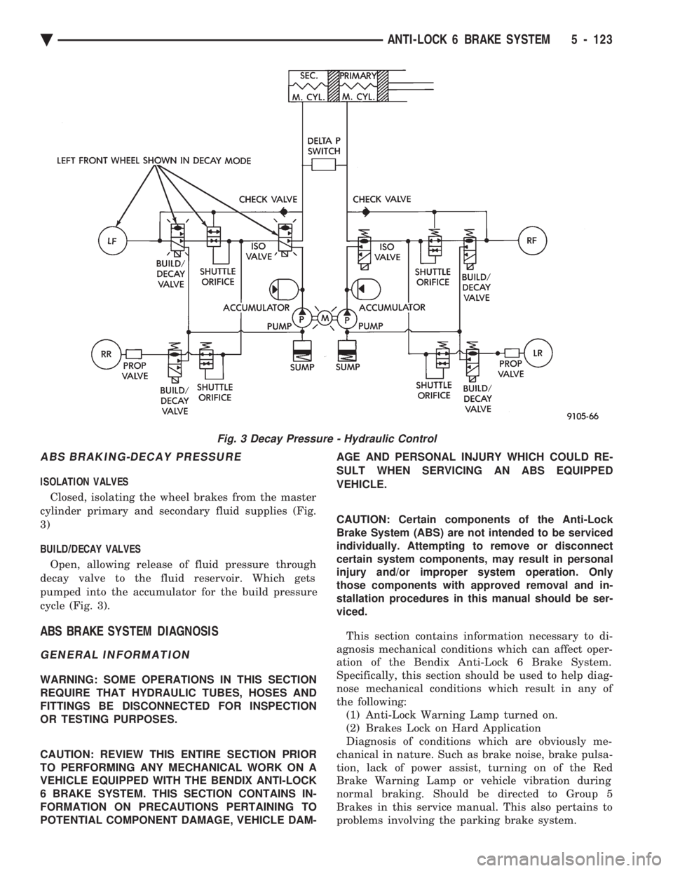
ABS BRAKING-DECAY PRESSURE
ISOLATION VALVES Closed, isolating the wheel brakes from the master
cylinder primary and secondary fluid supplies (Fig.
3)
BUILD/DECAY VALVES
Open, allowing release of fluid pressure through
decay valve to the fluid reservoir. Which gets
pumped into the accumulator for the build pressure
cycle (Fig. 3).
ABS BRAKE SYSTEM DIAGNOSIS
GENERAL INFORMATION
WARNING: SOME OPERATIONS IN THIS SECTION
REQUIRE THAT HYDRAULIC TUBES, HOSES AND
FITTINGS BE DISCONNECTED FOR INSPECTION
OR TESTING PURPOSES.
CAUTION: REVIEW THIS ENTIRE SECTION PRIOR
TO PERFORMING ANY MECHANICAL WORK ON A
VEHICLE EQUIPPED WITH THE BENDIX ANTI-LOCK
6 BRAKE SYSTEM. THIS SECTION CONTAINS IN-
FORMATION ON PRECAUTIONS PERTAINING TO
POTENTIAL COMPONENT DAMAGE, VEHICLE DAM- AGE AND PERSONAL INJURY WHICH COULD RE-
SULT WHEN SERVICING AN ABS EQUIPPED
VEHICLE.
CAUTION: Certain components of the Anti-Lock
Brake System (ABS) are not intended to be serviced
individually. Attempting to remove or disconnect
certain system components, may result in personal
injury and/or improper system operation. Only
those components with approved removal and in-
stallation procedures in this manual should be ser-
viced.
This section contains information necessary to di-
agnosis mechanical conditions which can affect oper-
ation of the Bendix Anti-Lock 6 Brake System.
Specifically, this section should be used to help diag-
nose mechanical conditions which result in any of
the following: (1) Anti-Lock Warning Lamp turned on.
(2) Brakes Lock on Hard Application
Diagnosis of conditions which are obviously me-
chanical in nature. Such as brake noise, brake pulsa-
tion, lack of power assist, turning on of the Red
Brake Warning Lamp or vehicle vibration during
normal braking. Should be directed to Group 5
Brakes in this service manual. This also pertains to
problems involving the parking brake system.
Fig. 3 Decay Pressure - Hydraulic Control
Ä ANTI-LOCK 6 BRAKE SYSTEM 5 - 123
Page 379 of 2438

After 15 seconds, record the loaded voltage reading
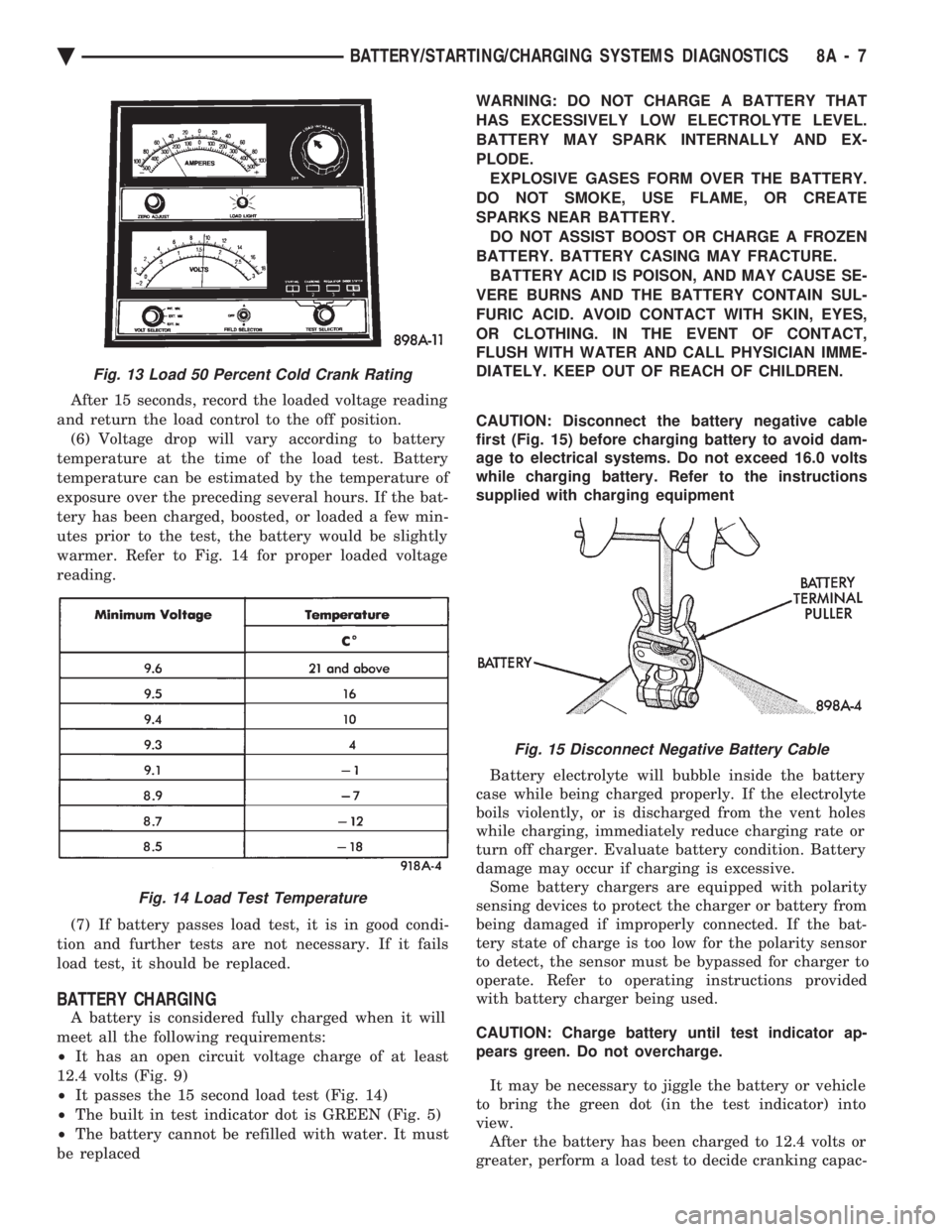
and return the load control to the off position. (6) Voltage drop will vary according to battery
temperature at the time of the load test. Battery
temperature can be estimated by the temperature of
exposure over the preceding several hours. If the bat-
tery has been charged, boosted, or loaded a few min-
utes prior to the test, the battery would be slightly
warmer. Refer to Fig. 14 for proper loaded voltage
reading.
(7) If battery passes load test, it is in good condi-
tion and further tests are not necessary. If it fails
load test, it should be replaced.
BATTERY CHARGING
A battery is considered fully charged when it will
meet all the following requirements:
² It has an open circuit voltage charge of at least
12.4 volts (Fig. 9)
² It passes the 15 second load test (Fig. 14)
² The built in test indicator dot is GREEN (Fig. 5)
² The battery cannot be refilled with water. It must
be replaced WARNING: DO NOT CHARGE A BATTERY THAT
HAS EXCESSIVELY LOW ELECTROLYTE LEVEL.
BATTERY MAY SPARK INTERNALLY AND EX-
PLODE. EXPLOSIVE GASES FORM OVER THE BATTERY.
DO NOT SMOKE, USE FLAME, OR CREATE
SPARKS NEAR BATTERY. DO NOT ASSIST BOOST OR CHARGE A FROZEN
BATTERY. BATTERY CASING MAY FRACTURE. BATTERY ACID IS POISON, AND MAY CAUSE SE-
VERE BURNS AND THE BATTERY CONTAIN SUL-
FURIC ACID. AVOID CONTACT WITH SKIN, EYES,
OR CLOTHING. IN THE EVENT OF CONTACT,
FLUSH WITH WATER AND CALL PHYSICIAN IMME-
DIATELY. KEEP OUT OF REACH OF CHILDREN.
CAUTION: Disconnect the battery negative cable
first (Fig. 15) before charging battery to avoid dam-
age to electrical systems. Do not exceed 16.0 volts
while charging battery. Refer to the instructions
supplied with charging equipment
Battery electrolyte will bubble inside the battery
case while being charged properly. If the electrolyte
boils violently, or is discharged from the vent holes
while charging, immediately reduce charging rate or
turn off charger. Evaluate battery condition. Battery
damage may occur if charging is excessive. Some battery chargers are equipped with polarity
sensing devices to protect the charger or battery from
being damaged if improperly connected. If the bat-
tery state of charge is too low for the polarity sensor
to detect, the sensor must be bypassed for charger to
operate. Refer to operating instructions provided
with battery charger being used.
CAUTION: Charge battery until test indicator ap-
pears green. Do not overcharge.
It may be necessary to jiggle the battery or vehicle
to bring the green dot (in the test indicator) into
view. After the battery has been charged to 12.4 volts or
greater, perform a load test to decide cranking capac-
Fig. 13 Load 50 Percent Cold Crank Rating
Fig. 14 Load Test Temperature
Fig. 15 Disconnect Negative Battery Cable
Ä BATTERY/STARTING/CHARGING SYSTEMS DIAGNOSTICS 8A - 7
Page 458 of 2438

(3) Inspect the spark plug condition. Refer to Spark
Plug Condition in this section.
SPARK PLUG GAP ADJUSTMENT
Check the spark plug gap with a gap gauge. If the
gap is not correct, adjust it by bending the ground
electrode (Fig. 6).
SPARK PLUG INSTALLATION
(1) Start the spark plug into the cylinder head by
hand to avoid cross threading. (2) Tighten spark plugs to 28 N Im (20 ft. lbs.)
torque. (3) Install spark plug cables over spark plugs.
IDLE RPM TESTÐ2.5L AND 3.0L ENGINES
WARNING: APPLY PARKING BRAKE AND/OR BLOCK
WHEELS BEFORE PERFORMING IDLE CHECK OR
ADJUSTMENT, OR ANY TESTS WITH A RUNNING
ENGINE.
Engine idle set rpmshould be recorded when the
vehicle is first brought into shop for testing. This
will assist in diagnosing complaints of engine stalling,
creeping and hard shifting on vehicles equipped with
automatic transaxles. Proceed to the Throttle Body Minimum Airflow pro-
cedures in Group 14.
IGNITION TIMING PROCEDUREÐ2.2L TBI, 2.5L
TBI, 2.5L MPI, AND 3.0L ENGINES
WARNING: APPLY PARKING BRAKE AND/OR BLOCK
WHEELS BEFORE PERFORMING SETTING IGNITION
TIMING OR PERFORMING ANY TEST ON AN OPER-
ATING ENGINE.
Proper ignition timing is required to obtain optimum
engine performance. The distributor must be correctly
indexed to provide correct initial ignition timing. (1) Set the gearshift selector in park or neutral and
apply the parking brake. All lights and accessories
must be off. (2) If using a magnetic timing light, insert the
pickup probe into the open receptacle next to the
timing scale window. If a magnetic timing unit is not
available, use a conventional timing light connected to
the number one cylinder spark plug cable. Do not puncture cables, boots or nipples with
test probes. Always use proper adapters. Punc-
turing the spark plug cables with a probe will
damage the cables. The probe can separate the
conductor and cause high resistance. In addition
breaking the rubber insulation may permit sec-
ondary current to arc to ground. (3) Turn selector switch to the appropriate cylinder
position. (4) Start engine and run until operating tempera-
ture is obtained. (5) With the engine at normal operating tempera-
ture, connect the DRBII scan tool to the data link
connector (diagnostic connector). Access the State Dis-
play screen. Refer to the appropriate Powertrain Diag-
nostics Procedures Manual. If not using the DRBII
scan tool, disconnect the coolant temperature
sensor electrical connector. The electric radiator
fan will operate and the malfunction indicator lamp
(instrument panel Check Engine light) will turn on
after disconnecting the coolant sensor or starting the
DRBII scan tool procedure. (6) Aim Timing Light at timing scale (Fig. 7 or Fig.
8) or read magnetic timing unit. If flash occurs when
timing mark is before specified degree mark, timing is
advanced. To adjust, turn distributor housing in direc-
tion of rotor rotation. If flash occurs when timing mark is after specified
degree mark, timing is retarded. To adjust, turn dis-
tributor housing against direction of rotor rotation.
Refer to Vehicle Emission Control Information label for
correct timing specification. If timing is within 62É of
value specified on the label, proceed to step (8). If
outside specified tolerance, proceed to next step. (7) Loosen distributor hold-down arm screw
enough to rotate the distributor housing (Fig. 9 or
Fig. 6 Setting Spark Plug GapÐTypical
8D - 16 IGNITION SYSTEMS Ä
Page 483 of 2438

(2) With engine running, move test probe along
entire length of all cables (approximately 0 to 1/8
inch gap). If punctures or cracks are present there
will be a noticeable spark jump from the faulty area
to the probe. Cracked, leaking or faulty cables should
be replaced. Use the following procedure when removing the
high tension cable from the spark plug. First, remove
the cable from the retaining bracket. Then grasp the
terminal as close as possible to the spark plug. Ro-
tate the cover (boot) slightly and pull straight back.
Do not use pliers and do not pull the cable at an
angle. Doing so will damage the insulation, cable
terminal or the spark plug insulator. Wipe spark
plug insulator clean before reinstalling cable
and cover. Resistance cables are identified by the words Elec-
tronic Suppression .
Use an ohmmeter to check cables for opens, loose
terminals or high resistance. (a) Remove cable from spark plug.
(b) Remove cable from the coil tower.
(c) Connect the ohmmeter between spark plug
end terminal and the coil end terminal. Resistance
should be within tolerance shown in the cable re-
sistance chart. If resistance is not within tolerance,
replace cable assembly. Test all spark plug cables
in same manner.
SPARK PLUG SERVICE
When replacing the spark plug cables, route the ca-
bles correctly and secure them in the appropriate re-
tainers. Incorrectly routed cables can cause the radio
to reproduce ignition noise. It can also cause cross ig-
nition of the spark plugs or short circuit the cables to
ground.
SPARK PLUG REMOVAL
Always remove cables by grasping at boot, rotating
the boot 1/2 turn, and pulling straight back in a
steady motion. (1) Prior to removing the spark plug spray com-
pressed air around the spark plug hole and the area
around the spark plug. (2) Remove the spark plug using a quality socket
with a rubber or foam insert. (3) Inspect the spark plug condition. Refer to
Spark Plug Condition in this section.
SPARK PLUG GAP ADJUSTMENT
Check the spark plug gap with a gap gauge. If the
gap is not correct, adjust it by bending the ground
electrode (Fig. 6).
SPARK PLUG INSTALLATION
(1) To avoid cross threading, start the spark plug
into the cylinder head by hand. (2) Tighten spark plugs to 28 N Im (20 ft. lbs.)
torque. (3) Install spark plug cables over spark plugs.
IDLE RPM TEST
WARNING: BE SURE TO APPLY PARKING BRAKE
AND/OR BLOCK WHEELS BEFORE PERFORMING
ANY ENGINE RUNNING TESTS.
Engine idle set rpmshould be tested and recorded
as it is when the vehicle is first brought into shop
for testing. This will assist in diagnosing complaints
of engine stalling, creeping and hard shifting on ve-
hicles equipped with automatic transaxle. Refer to the
Throttle Body Minimum Airflow procedures in Group
14.
IGNITION TIMING PROCEDURE
Ignition timing cannot be changed or set on Turbo
III, 3.3L or 3.8L engines. For diagnostic information,
refer to the DRBII scan tool and the appropriate
Powertrain Diagnostics Procedures manual.
CABLE RESISTANCE CHART
Fig. 6 Setting Spark Plug GapÐTypical
Ä IGNITION SYSTEMS 8D - 41
Page 1699 of 2438

CAUTION: Avoid application of rust prevention
compounds or undercoating materials to exhaust
system floor pan heat shields on cars if equipped.
Light overspray near the edges is permitted. Appli-
cation of coating will greatly reduce the efficiency
of the heat shields resulting in excessive floor pan
temperatures and objectionable fumes.
The combustion reaction caused by the catalyst re-
leases additional heat in the exhaust system. Caus-
ing temperature increases in the area of the reactor
under severe operating conditions. Such conditions
can exist when the engine misfires or otherwise does
not operate at peak efficiency. Do notremove spark
plug wires from plugs or by any other means short
out cylinders if exhaust system is equipped with cat-
alytic converter. Failure of the catalytic converter
can occur due to temperature increases caused by un-
burned fuel passing through the converter. The use of the catalysts also involves some non-au-
tomotive problems. Unleaded gasoline must be used
to avoid poisoning the catalyst core. Do not allow en- gine to operate above 1200 RPM in neutral for ex-
tended periods over 5 minutes. This condition may
result in excessive exhaust system/floor pan temper-
atures because of no air movement under the vehicle.
EXHAUST GAS RECIRCULATION (EGR) SYSTEM
To assist in the control of oxides of nitrogen (NOx)
in engine exhaust, some engines are equipped with
an exhaust gas recirculation system. The use of ex-
haust gas to dilute incoming air/fuel mixtures lowers
peak flame temperatures during combustion, thus
limiting the formation of NOx. Exhaust gases are taken from openings in the ex-
haust gas crossover passage in the intake manifold.
REFER TO SECTION 25 EMISSION SYSTEMS
FOR A COMPLETE DESCRIPTION, DIAGNOSIS
AND SERVICE PROCEDURES ON THE EXHAUST
GAS RECIRCULATION SYSTEM AND COMPO-
NENTS.
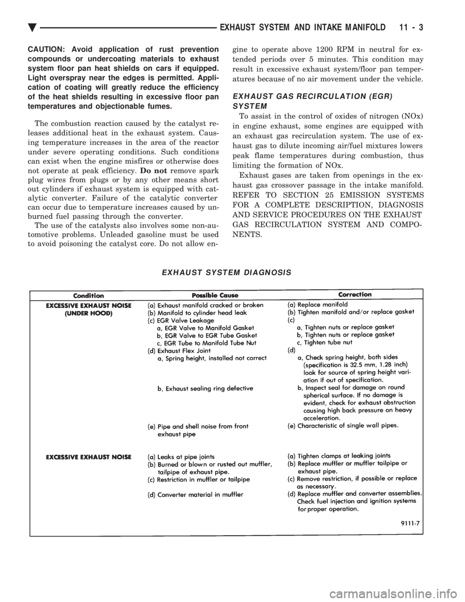
EXHAUST SYSTEM DIAGNOSIS
Ä EXHAUST SYSTEM AND INTAKE MANIFOLD 11 - 3
Page 1782 of 2438

once the system has entered closed loop. Refer to
Modes of Operation in this section for an explanation
of closed loop operation.
NON-MONITORED CIRCUITS
The PCM does not monitor the following circuits,
systems and conditions that could have malfunctions
that result in driveability problems. Diagnostic trou-
ble codes may not be displayed for these conditions.
However, problems with these systems may cause di-
agnostic trouble codes to be displayed for other sys-
tems. For example, a fuel pressure problem will not
register a fault directly, but could cause a rich or
lean condition. This could cause an oxygen sensor
fault to be stored in the PCM. Fuel Pressure - Fuel pressure is controlled by the
fuel pressure regulator. The PCM cannot detect a
clogged fuel pump inlet filter, clogged in-line fuel fil-
ter, or a pinched fuel supply or return line. However,
these could result in a rich or lean condition causing
an oxygen sensor fault. Secondary Ignition Circuit - The PCM cannot
detect an inoperative ignition coil, fouled or worn
spark plugs, ignition cross firing, or open spark plug
cables. Engine Timing - The PCM cannot detect an incor-
rectly indexed timing chain, camshaft sprocket and
crankshaft sprocket. The PCM also cannot detect an
incorrectly indexed distributor. However, these could
result in a rich or lean condition causing an oxygen
sensor fault to be stored in the PCM. Cylinder Compression - The PCM cannot detect
uneven, low, or high engine cylinder compression. Exhaust System
- The PCM cannot detect a
plugged, restricted or leaking exhaust system. Fuel Injector Malfunctions - The PCM cannot
determine if the fuel injector is clogged, the pintle is
sticking or the wrong injector is installed. However,
these could result in a rich or lean condition causing
an oxygen sensor fault to be stored in the PCM. Excessive Oil Consumption - Although the PCM
monitors the exhaust stream oxygen content through
the oxygen sensor when the system is in closed loop,
it cannot determine excessive oil consumption. Throttle Body Air Flow - The PCM cannot detect
a clogged or restricted air cleaner inlet or filter ele-
ment. Evaporative System - The PCM will not detect a
restricted, plugged or loaded evaporative purge can-
ister. Vacuum Assist - Leaks or restrictions in the vac-
uum circuits of vacuum assisted engine control sys-
tem devices are not monitored by the PCM. However,
these could result in a MAP sensor fault being stored
in the PCM. PCM System Ground - The PCM cannot deter-
mine a poor system ground. However, a diagnostic
trouble code may be generated as a result of this con-
dition. PCM Connector Engagement - The PCM cannot
determine spread or damaged connector pins. How-
ever, a diagnostic trouble code may be generated as a
result of this condition.
HIGH AND LOW LIMITS
The powertrain control module (PCM) compares in-
put signal voltages from each input device with es-
tablished high and low limits that are programmed
into it for that device. If the input voltage is not
within specifications and other diagnostic trouble
code criteria are met, a diagnostic trouble code will
be stored in memory. Other diagnostic trouble code
criteria might include engine RPM limits or input
voltages from other sensors or switches that must be
present before a fault condition can be verified.
DIAGNOSTIC TROUBLE CODE DESCRIPTION
When a diagnostic trouble code appears, it indi-
cates the powertrain control module (PCM) has rec-
ognized an abnormal condition in the system.
Diagnostic trouble codes can be obtained from the
malfunction indicator lamp (instrument panel Check
Engine lamp) on the Instrument Panel or from the
DRBII scan tool. Diagnostic trouble codes indicate
the results of a failure but do not identify the failed
component directly.
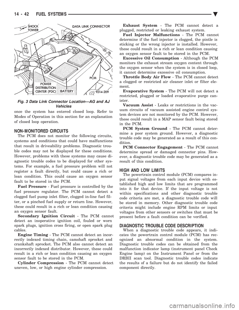
Fig. 3 Data Link Connector LocationÐAG and AJ Vehicles
14 - 42 FUEL SYSTEMS Ä