1993 CHEVROLET PLYMOUTH ACCLAIM tire pressure
[x] Cancel search: tire pressurePage 35 of 2438
COMPONENT AND SYSTEM INDEX
Name Group-page Name Group-page
BRAKES ..................................5-1
BENDIX ANTILOCK 4 BRAKE SYSTEM ...........5-12
ABS BRAKE SYSTEM DIAGNOSTIC FEATURES.......5-24
ABS SYSTEM SELF DIAGNOSIS................ 5-24
BENDIX ANTILOCK 4 BRAKE SYSTEM DIAGNOSTICS....5-25
CONTROLLER ANTILOCK BRAKE CAB............. 5-24
LATCHING VERSUS NON-LATCHING ABS FAULTS.......5-25
START-UP CYCLE........................ 5-24
ABS COMPUTER SYSTEM SERVICE PRECAUTIONS....5-23
ABS GENERAL SERVICE PRECAUTIONS........... 5-23
ABS BRAKE SYSTEM ON VEHICLE SERVICE.........5-23
TEST DRIVING ABS COMPLAINT VEHICLES.......... 5-23
WHEEL SPEED SENSOR CABLES............... 5-23
ANTILOCK BRAKE SYSTEM COMPONENTS..........5-16
BUILD/DECAY VALVES..................... 5-16
FLUID SUMPS.......................... 5-17
HYDRAULIC SPRING ACCUMULATOR.............5-17
MODULATOR ASSEMBLY.................... 5-16
PRESSURE DIFFERENTIAL SWITCH..............5-17
PROPORTIONING VALVES................... 5-17
PUMP/MOTOR ASSEMBLY...................5-17
SHUTTLE ORIFICE........................ 5-16
WHEEL SPEED SENSORS....................5-18
ANTILOCK BRAKE SYSTEM DEFINITIONS..........5-14
ANTILOCK BRAKES OPERATION AND PERFORMANCE. . . 5-15
ANTILOCK BRAKE SYSTEM OPERATION............ 5-15
PEDAL FEEL........................... 5-15
TIRE NOISE & MARKS.....................5-15
ANTILOCK SYSTEM RELAYS AND WARNING LAMPS. . . 5-19
ANTILOCK WARNING LAMP DIODE..............5-20
Antilock Warning Lamp Off................... 5-20
Antilock Warning Lamp On...................5-20
PUMP/MOTOR RELAY...................... 5-20
SYSTEM RELAY......................... 5-19
BENDIX ANTILOCK 4 BRAKE SYSTEM DIAGNOSTICS. . . 5-22
DEFINITIONS........................... 5-23
GENERAL INFORMATION....................5-22
BLEEDING BENDIX ANTILOCK 4 BRAKE SYSTEM......5-25
BENDIX ANTILOCK 4 MODULATOR ASSEMBLY BLEEDING
PROCEDURE
......................... 5-26
HYDRAULIC BRAKE TUBE ASSEMBLY (JUNCTION BLOCK
TO MODULATOR ASSEMBLY)
................ 5-34
INSTALL............................ 5-36
REMOVE............................5-34
MASTER CYLINDER AND POWER BOOSTER.........5-38
REMOVAL AND INSTALLATION................. 5-38
MODULATOR ASSEMBLY CIRCUIT BLEEDING PROCEDURE
AND SEQUENCE
....................... 5-26
1 MODULATOR PRIMARY CHECK VALVE CIRCUIT........5-26
2 MODULATOR SECONDARY CHECK VALVE CIRCUIT......5-26
3 MODULATOR ASSEMBLY PRIMARY SUMP CIRCUIT......5-27
4 MODULATOR ASSEMBLY PRIMARY ACCUMULATOR CIRCUIT. 5-27
5 MODULATOR ASSEMBLY SECONDARY SUMP CIRCUIT....5-28
6 MODULATOR ASSEMBLY SECONDARY ACCUMULATOR
CIRCUIT
........................... 5-29
MODULATOR ASSEMBLY (FIG. 1)...............5-30
INSTALL............................ 5-32
REMOVE............................5-30
PROPORTIONING VALVES (FIG. 1)...............5-38
INSTALL............................ 5-39
REMOVAL...........................5-38
PUMP/MOTOR SERVICE....................5-29
CONTROLLER ANTILOCK BRAKE CAB.............5-18
CONTROLLER ANTILOCK BRAKE (INPUTS)..........5-19
CONTROLLER ANTILOCK BRAKE (OUTPUTS).........5-19
DIAGNOSTIC CONNECTOR.................... 5-19
ELECTRONIC COMPONENTS..................5-41
CONTROLLER ANTILOCK BRAKE CAB.............5-41
INSTALL............................ 5-42
REMOVE............................5-41
FRONT WHEEL SPEED SENSOR (FIG. 9)...........5-43
INSTALLATION......................... 5-44
REMOVAL........................... 5-43
REAR WHEEL SPEED SENSOR (FIGS. 10 AND 11)......5-44
INSTALLATION......................... 5-44
REMOVAL........................... 5-44
REMOVAL/INSTALLATION OF SYSTEM RELAY.........5-42
INSTALL............................ 5-43
REMOVE............................5-43
REMOVE/INSTALL PUMP MOTOR RELAY...........5-43
WHEEL SPEED SENSORS.................... 5-43
INSPECTION.......................... 5-43
GENERAL INFORMATION....................5-12
HYDRAULIC CIRCUITS AND VALVE OPERATION......5-20
ABS BRAKING-BUILD PRESSURE............... 5-20
BUILD/DECAY VALVES..................... 5-20
ABS BRAKING-DECAY PRESSURE...............5-22
BUILD/DECAY VALVES..................... 5-22
NORMAL BRAKING....................... 5-20
BUILD/DECAY VALVES.....................5-20
MAJOR COMPONENTS...................... 5-14
CONTROLLER ANTILOCK BRAKE CAB.............5-14
MASTER CYLINDER AND VACUUM BOOSTER.........5-14
MODULATOR AND PUMP MOTOR/ASSEMBLY.........5-14
WHEEL SPEED SENSORS.................... 5-14
MECHANICAL DIAGNOSTICS AND SERVICE
PROCEDURES
.......................... 5-24
INTERMITTENT FAULTS.....................5-24
SPECIAL SERVICE TOOL....................5-24
DRB DIAGNOSTIC TESTER...................5-24
NORMAL BRAKE SYSTEM FUNCTION.............5-14
ON-CAR ABS BRAKE SYSTEM SERVICE...........5-25
CHECKING BRAKE FLUID LEVEL................ 5-25
GENERAL SERVICE PRECAUTIONS...............5-25
SPECIFICATIONS......................... 5-46
SYSTEM SELF-DIAGNOSTICS..................5-15
VEHICLE PERFORMANCE.................... 5-15
WARNING SYSTEMS OPERATION...............5-16
NORMAL OPERATION OF WARNING LAMP..........5-16
GENERAL INFORMATION .....................5-1
HYDRAULIC SYSTEM CONTROL VALVES .........5-10
GENERAL INFORMATION.................... 5-10
HYDRAULIC SYSTEM SERVICE PROCEDURES........5-11
BRAKE WARNING SYSTEM................... 5-11
CHECKING BRAKE WARNING SWITCH UNIT...........5-11
TESTING ANTILOCK PROPORTIONING VALVES........5-11
PRESSURE DIFFERENTIAL WARNING LIGHT SWITCH. . . 5-10
SERVICE ADJUSTMENTS .....................5-3
Page 63 of 2438

FRONT SUSPENSION SERVICE PROCEDURES INDEX
page page
Ball Joints .............................. 13
Hub and Bearing Assembly ................. 20
Knuckle (Front Suspension) ................. 16
Lower Control Arm ....................... 10
Lower Control Arm Pivot Bushings ........... 11 Shock Absorbers (Strut Damper)
............. 10
Strut Damper Assembly ..................... 7
Suspension Coil Springs .................... 9
Sway Bar .............................. 14
Wheel Alignment .......................... 5
WHEEL ALIGNMENT
Front wheel alignment is the proper adjustment of
all interrelated front suspension angles. These angles
are what affects the running and steering of the
front wheels of the vehicle. The method of checking front alignment will vary
depending on the type of equipment being used. The
instructions furnished by the manufacturer of the
equipment should always be followed. With the ex-
ception that the alignment specifications recom-
mended by Chrysler Corporation be used. There are six basic factors which are the founda-
tion to front wheel alignment. These are height,
caster, camber, toe-in, steering axis inclination and
toe-out on turns. Of the six basic factors only camber
and toe in are mechanically adjustable (Fig. 1)
CAUTION: Do not attempt to modify any suspen-
sion or steering components by heating or bending
of the component.
Wheel alignment adjustments and checks should be
made in the following sequence. (1) Camber
(2) Toe
Camber is the number of degrees the top of the
wheel is tilted inward or outward from true vertical.
Inward tilt is negative camber. Outward tilt is posi-
tive camber. Excessive camber is a tire wear factor: negative
camber causes wear on the inside of the tire, while
positive camber causes wear to the outside. Toe
is measured in degrees or inches and is the
distance the front edges of the tires are closer (or far-
ther apart) than the rear edges. See Front Wheel
Drive Specifications for Toesettings.
PRE-ALIGNMENT
Before any attempt is made to change or correct
the wheel alignment factors. The following inspection
and necessary corrections must be made on those
parts which influence the steering of the vehicle. (1) Check and inflate tires to recommended pres-
sure. All tires should be the same size and in good
condition and have approximately the same wear.
Note type of tread wear which will aid in diagnosing,
see Wheels and Tires, Group 22. (2) Check front wheel and tire assembly for radial
runout. (3) Inspect lower ball joints and all steering link-
age for looseness. (4) Check for broken or sagged front and rear
springs. Front suspension must only be checked after the
vehicle has had the following checked or adjusted.
Tires set to recommended pressures, full tank of fuel,
no passenger or luggage compartment load and is on
a level floor or alignment rack. Just prior to each alignment reading. The vehicle
should be bounced (rear first, then front) by grasping
bumper at center and jouncing each end an equal
number of times. Always release bumpers at bottom
of down cycle.
Ä SUSPENSION AND DRIVESHAFTS 2 - 5
Page 104 of 2438

(9) Hold the binding strip with the left hand and
push the Tool forward and slightly upward. Then fit
the hook of the Tool into the eye of the buckle (Fig.
7).
(10) Tighten the strip by closing the tool handles
(Fig. 8). Then rotate the tool (handles) downward
while slowly releasing the pressure on the tool han-
dles. Allow the tool (handles) to open progressively.
Then open the tool entirely and remove them side-
ways.
(11) If the strap is not tight enough, engage the
tool a second or even a third time, always about 13
mm (1/2 inch) from the buckle (Fig. 9). When tight-
ening always be careful to see that the strap slides in
a straight line and without resistance in the buckle,
that is without making a fold. An effective grip will
be obtained only by following the above instructions. (12) Fig. 10 shows WHAT NOT TO DO, NEVER
fold the strap back or bring the tool down while
tightening, this action will break the strap. (13) Fig. 11 shows how to pull the tool down while
releasing the pressure on the tool handle.
Fig. 7 Push Tool Forward & Fit into Buckle Eye
Fig. 8 Tighten Strap
Fig. 9 Tighten Strap (if Required)
Fig. 10 What Not to Do
Fig. 11 Correct Tightening Procedure
2 - 46 SUSPENSION AND DRIVESHAFTS Ä
Page 136 of 2438
(3) Check solenoid to volume canister joint.
² Front strut to solenoid valve connection.
² Rear spring to solenoid valve connection.
(4) Check air line for ruptures, cuts, splits or heat
damage. Use a soap and water solution or a liquid de-
veloped for leak detection.
SYSTEM OPERATION
ENGINE RUN OPERATION
The system will compensate for load
addition/removal when.
² The trunk and all doors are closed.
² The engine speed exceeds 600 R.P.M.
² Throttle angle is less than 65 degrees.
² The brake is not applied.
² You are not cornering above 10 mph.
² There is not a charging system problem with the
vehicle.
ENGINE OFF OPERATION
After passengers/load is removed from the vehicle
the system will correct the vehicle attitude after:
² The trunk and all doors are closed.
² The ignition switch is in the OFF position.
Opening the a door or trunk wakes up the body
computer and the air suspension module. The air
suspension system is now capable of leveling, if
required.
LONG TERM IGNITION OFF OPERATION
The system is capable of one an additional leveling
cycle. After 2 continuous hours of ignition key off and
no door open or trunk open activities. This feature is
implemented to eliminate possible ice freeze-up be-
tween the tire and the inner fender shield.
SYSTEM OPERATION INHIBITORS
The air suspension system is inhibited when:
² The trunk is open.
² A door(s) is/are open.
² The brake pedal is engaged.
² The throttle is at the wide open position.
² The charging system fails.
The maximum compressor pump or exhaust
time is 3 minutes.
SYSTEM FAILURES
Vehicles equipped with air suspension and overhead
console. Will alert the driver of an air suspension
system malfunction. A warning Check Air Suspension
will appear on the overhead console screen.
SAFETY CONCERNS
WARNING: REAR AIR SPRINGS MUST BE DEFLATED
BEFORE BEING REMOVED FROM THE VEHICLE.
WARNING: OPEN TRUNK, OR DOOR(S) OR REMOVE
GROUND STRAP FROM BATTERY BEFORE HOIST-
ING OR JACKING A VEHICLE DURING MECHANICAL
REPAIRS.
WARNING: IF THE VEHICLE NEEDS SERVICE OR
REPAIR OF THE REAR SHOCK ABSORBERS OR
REAR AXLE PIVOT BUSHINGS. THE REAR AIR
SPRINGS MUST HAVE THE AIR PRESSURE RE-
MOVED BEFORE THE VEHICLE CAN BE SERVICED
SAFELY.
SHIPPING MODE
(1) Removing shipping height signal for customer
use.
² Use DRB II tester and 1991 Chassis (Air Suspen-
sion) service cartridge.
² Follow DRB II requirements to cancel shipping
height message in the body computer.
² Connect the Ignition Off Draw (I.O.D.) circuit.
The connection of the IOD circuit will cancel
the Shipping height signal. (2) Return to shipping height.
² Set shipping command in the body computer using
the DRB II and the 1991 Chassis (Air suspension)
service cartridge.
² Disconnect the I.O.D. connector.
DIAGNOSIS
INITIAL DIAGNOSTIC CHECK
(1) Check for blown or missing fuses.
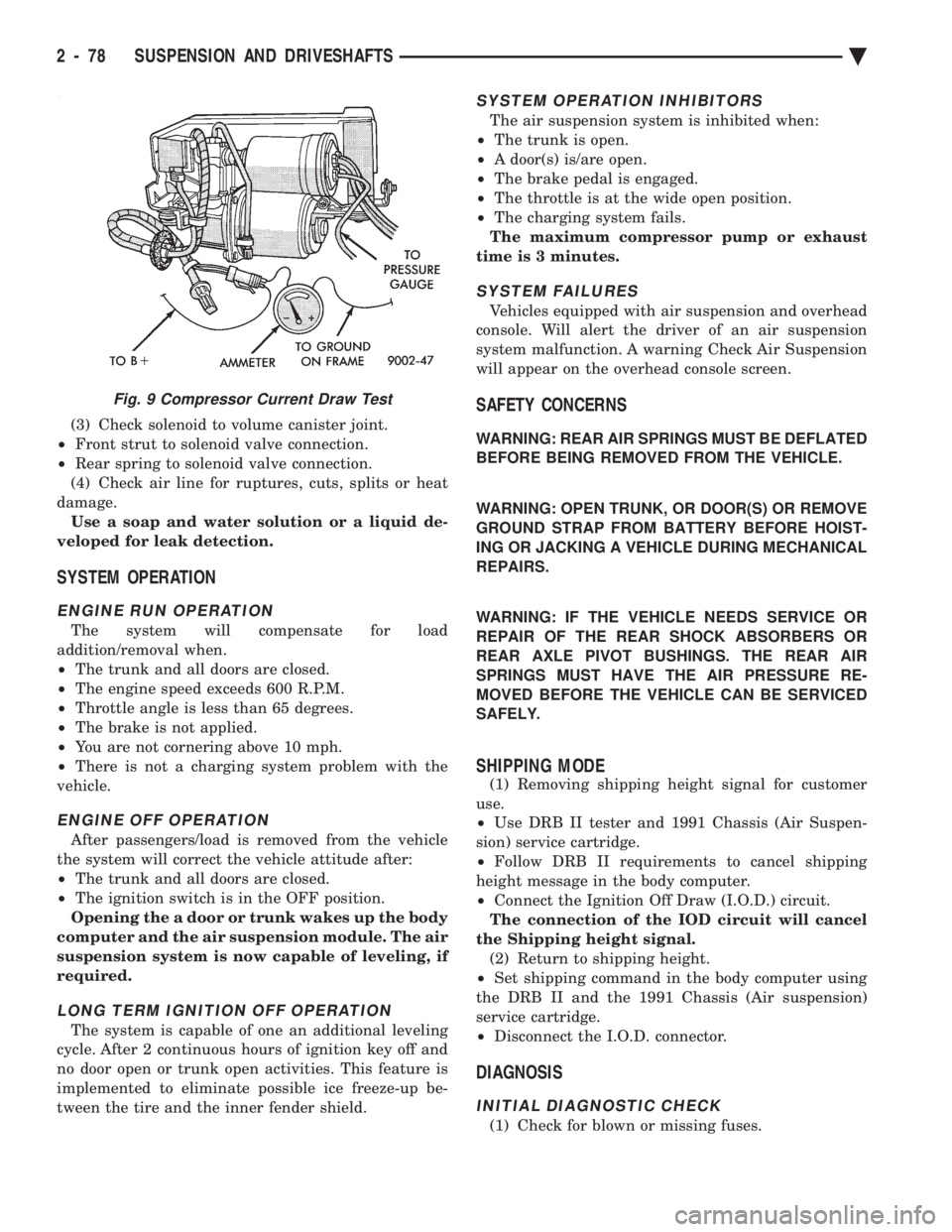
Fig. 9 Compressor Current Draw Test
2 - 78 SUSPENSION AND DRIVESHAFTS Ä
Page 144 of 2438
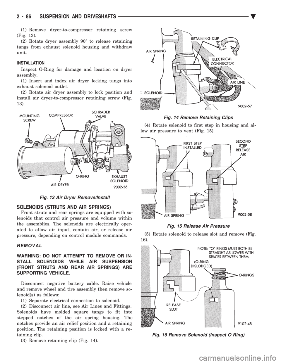
(1) Remove dryer-to-compressor retaining screw
(Fig. 13). (2) Rotate dryer assembly 90É to release retaining
tangs from exhaust solenoid housing and withdraw
unit.
INSTALLATION
Inspect O-Ring for damage and location on dryer
assembly. (1) Insert and index air dryer locking tangs into
exhaust solenoid outlet. (2) Rotate air dryer assembly to lock position and
install air dryer-to-compressor retaining screw (Fig.
13).
SOLENOIDS (STRUTS AND AIR SPRINGS)
Front struts and rear springs are equipped with so-
lenoids that control air pressure and volume within
the assemblies. The solenoids are electrically oper-
ated to allow air input, contain air, or release air
pressure, depending on control module commands.
REMOVAL
WARNING: DO NOT ATTEMPT TO REMOVE OR IN-
STALL SOLENOIDS WHILE AIR SUSPENSION
(FRONT STRUTS AND REAR AIR SPRINGS) ARE
SUPPORTING VEHICLE.
Disconnect negative battery cable. Raise vehicle
and remove wheel and tire assembly then remove so-
lenoid(s) as follows: (1) Separate electrical connection to solenoid.
(2) Disconnect air line, see Air Lines and Fittings.
Solenoids have molded square tangs to fit into
stepped notches of the air spring housing. The
notches provide an air relief position and a retaining
position. The retaining position is locked with a re-
taining clip. (3) Remove retaining clip (Fig. 14). (4) Rotate solenoid to first step in housing and al-
low air pressure to vent (Fig. 15).
(5) Rotate solenoid to release slot and remove (Fig.
16).
Fig. 13 Air Dryer Remove/Install
Fig. 14 Remove Retaining Clips
Fig. 15 Release Air Pressure
Fig. 16 Remove Solenoid (Inspect O Ring)
2 - 86 SUSPENSION AND DRIVESHAFTS Ä
Page 190 of 2438
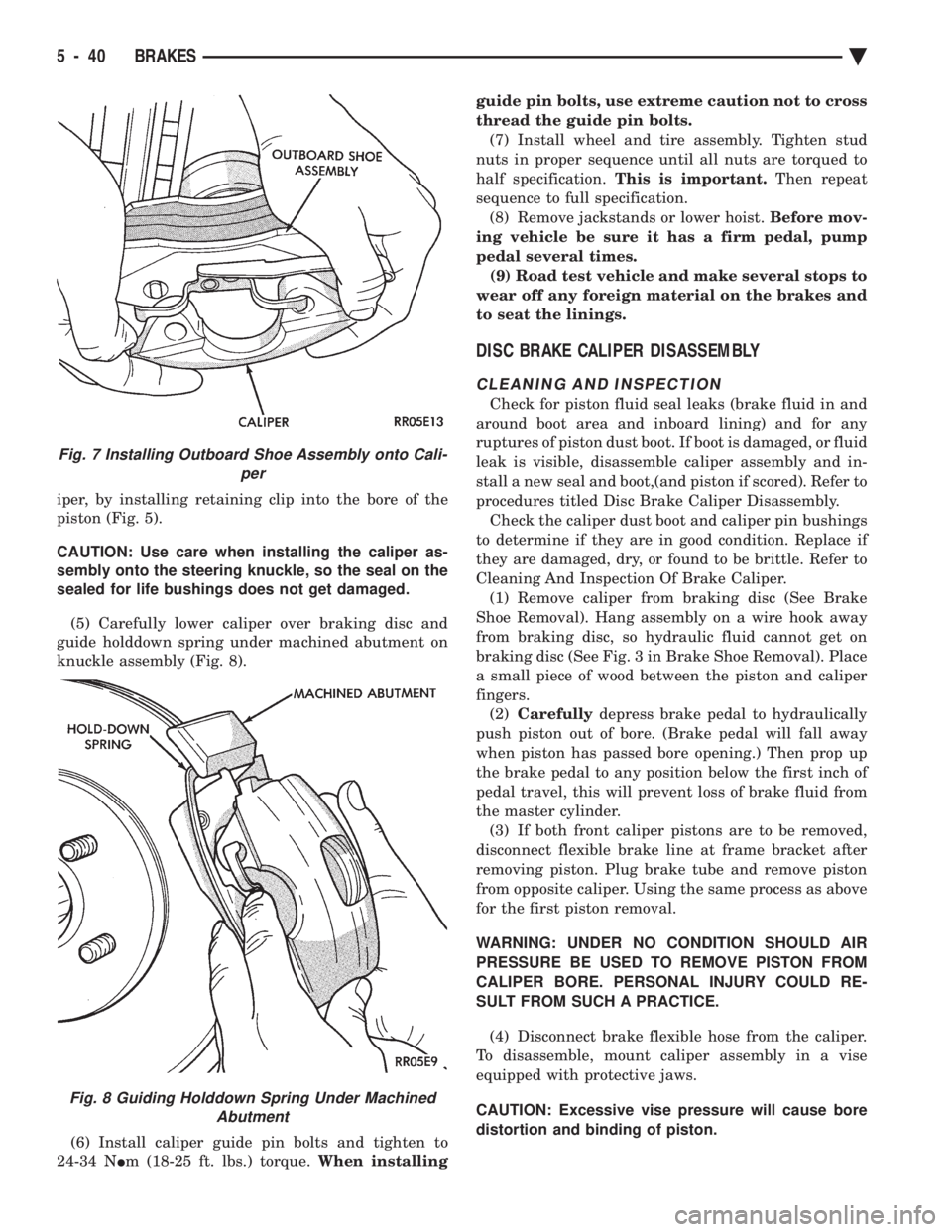
iper, by installing retaining clip into the bore of the
piston (Fig. 5).
CAUTION: Use care when installing the caliper as-
sembly onto the steering knuckle, so the seal on the
sealed for life bushings does not get damaged.
(5) Carefully lower caliper over braking disc and
guide holddown spring under machined abutment on
knuckle assembly (Fig. 8).
(6) Install caliper guide pin bolts and tighten to
24-34 N Im (18-25 ft. lbs.) torque. When installing guide pin bolts, use extreme caution not to cross
thread the guide pin bolts.
(7) Install wheel and tire assembly. Tighten stud
nuts in proper sequence until all nuts are torqued to
half specification. This is important. Then repeat
sequence to full specification. (8) Remove jackstands or lower hoist. Before mov-
ing vehicle be sure it has a firm pedal, pump
pedal several times. (9) Road test vehicle and make several stops to
wear off any foreign material on the brakes and
to seat the linings.
DISC BRAKE CALIPER DISASSEMBLY
CLEANING AND INSPECTION
Check for piston fluid seal leaks (brake fluid in and
around boot area and inboard lining) and for any
ruptures of piston dust boot. If boot is damaged, or fluid
leak is visible, disassemble caliper assembly and in-
stall a new seal and boot,(and piston if scored). Refer to
procedures titled Disc Brake Caliper Disassembly. Check the caliper dust boot and caliper pin bushings
to determine if they are in good condition. Replace if
they are damaged, dry, or found to be brittle. Refer to
Cleaning And Inspection Of Brake Caliper. (1) Remove caliper from braking disc (See Brake
Shoe Removal). Hang assembly on a wire hook away
from braking disc, so hydraulic fluid cannot get on
braking disc (See Fig. 3 in Brake Shoe Removal). Place
a small piece of wood between the piston and caliper
fingers. (2) Carefully depress brake pedal to hydraulically
push piston out of bore. (Brake pedal will fall away
when piston has passed bore opening.) Then prop up
the brake pedal to any position below the first inch of
pedal travel, this will prevent loss of brake fluid from
the master cylinder. (3) If both front caliper pistons are to be removed,
disconnect flexible brake line at frame bracket after
removing piston. Plug brake tube and remove piston
from opposite caliper. Using the same process as above
for the first piston removal.
WARNING: UNDER NO CONDITION SHOULD AIR
PRESSURE BE USED TO REMOVE PISTON FROM
CALIPER BORE. PERSONAL INJURY COULD RE-
SULT FROM SUCH A PRACTICE.
(4) Disconnect brake flexible hose from the caliper.
To disassemble, mount caliper assembly in a vise
equipped with protective jaws.
CAUTION: Excessive vise pressure will cause bore
distortion and binding of piston.
Fig. 7 Installing Outboard Shoe Assembly onto Cali- per
Fig. 8 Guiding Holddown Spring Under MachinedAbutment
5 - 40 BRAKES Ä
Page 221 of 2438

seal, a new seal should be used when reinstalling the
inner bearing. (See Fig. 1) (5) Thoroughly clean all old grease from the outer
and inner bearings, bearing cups and hub cavity (See
Fig. 1). To clean bearings, soak them in an ap-
propriate cleaning solvent. Strike the flat sur-
face of the bearing inner race against a
hardwood block several times. Immerse the
bearings in solvent between the blows to jar
grease loose and wash old particles of hardened
grease from bearings. Repeat this operation un-
til bearings are clean. Bearings can be dried
using compressed air but do not spin the bear-
ings. After cleaning, oil the bearings with engine
oil. Insert the bearing into its appropriate cup,
apply pressure to the bearing while rotating it to
test them for pitting and roughness. Replace all
worn or defective bearings. If bearing shows signs of pitting or roughness they should be
replaced. Bearings must be replaced as a set,
both the cup and the bearing need to be replaced
at the same time. If bearings are suitable for
further use, remove engine oil from bearings
using appropriate solvent and dry bearings. Re-
pack the bearings using a Multi-Purpose NLGI.
Grade 2 EP Grease such as Mopar or equivalent,
and place them in a clean covered container
until ready for installation. If a bearing packer is
not available, hand pack grease into all cavities
between bearing cage and rollers. (6) If bearings and cups are to be replaced, remove
cups from the drum or hub using a brass drift or
suitable remover. (7) Replace bearing cups with appropriate installing
tool. (8) Install inner bearing in grease coated hub and
bearing cup, and install new grease seals using the
appropriate seal installer. (9) Coat hub cavity and cup with grease.
(10) Before installing hub or drum assembly, inspect
stub axle and seal surface for burrs or roughness, and
smooth out all rough surfaces. (11) Coat the stub axle with Multi-Purpose NLGI,
Grade 2 EP grease such as Mopar or equivalent. (12) Carefully slide the hub of drum assembly onto
the stub axle. Do not drag seal or inner bearing
over the threaded area of the stub axle. (13) Install outer bearing, thrust washer and nut.
(14) Tighten the wheel bearing adjusting nut to 27 to
34 N Im (240 to 300 in. lbs.) while rotating hub or drum
assembly. This seats the bearings. (15) Back off adjusting nut 1/4 turn (90É) then
tighten adjusting nut only finger tight. (16) Position the nut lock over the bearing adjusting
nut with one pair of slots in line with the cotter pin hole
in the stub axle, and install cotter pin. (17) Install the grease caps and the wheel and tire
assemblies. Tighten wheel stud nuts to 115 N Im (85 ft.
lbs.) on all models. reinstall wheel covers if so
equipped.
Fig. 1 Rear Wheel Bearings
Ä BRAKES 5 - 71
Page 224 of 2438
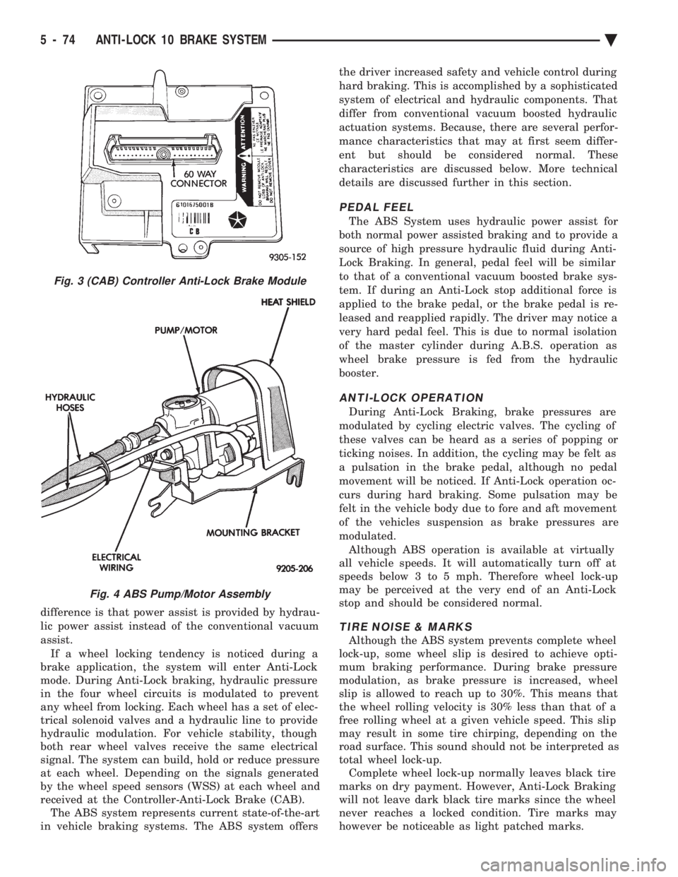
difference is that power assist is provided by hydrau-
lic power assist instead of the conventional vacuum
assist. If a wheel locking tendency is noticed during a
brake application, the system will enter Anti-Lock
mode. During Anti-Lock braking, hydraulic pressure
in the four wheel circuits is modulated to prevent
any wheel from locking. Each wheel has a set of elec-
trical solenoid valves and a hydraulic line to provide
hydraulic modulation. For vehicle stability, though
both rear wheel valves receive the same electrical
signal. The system can build, hold or reduce pressure
at each wheel. Depending on the signals generated
by the wheel speed sensors (WSS) at each wheel and
received at the Controller-Anti-Lock Brake (CAB). The ABS system represents current state-of-the-art
in vehicle braking systems. The ABS system offers the driver increased safety and vehicle control during
hard braking. This is accomplished by a sophisticated
system of electrical and hydraulic components. That
differ from conventional vacuum boosted hydraulic
actuation systems. Because, there are several perfor-
mance characteristics that may at first seem differ-
ent but should be considered normal. These
characteristics are discussed below. More technical
details are discussed further in this section.
PEDAL FEEL
The ABS System uses hydraulic power assist for
both normal power assisted braking and to provide a
source of high pressure hydraulic fluid during Anti-
Lock Braking. In general, pedal feel will be similar
to that of a conventional vacuum boosted brake sys-
tem. If during an Anti-Lock stop additional force is
applied to the brake pedal, or the brake pedal is re-
leased and reapplied rapidly. The driver may notice a
very hard pedal feel. This is due to normal isolation
of the master cylinder during A.B.S. operation as
wheel brake pressure is fed from the hydraulic
booster.
ANTI-LOCK OPERATION
During Anti-Lock Braking, brake pressures are
modulated by cycling electric valves. The cycling of
these valves can be heard as a series of popping or
ticking noises. In addition, the cycling may be felt as
a pulsation in the brake pedal, although no pedal
movement will be noticed. If Anti-Lock operation oc-
curs during hard braking. Some pulsation may be
felt in the vehicle body due to fore and aft movement
of the vehicles suspension as brake pressures are
modulated. Although ABS operation is available at virtually
all vehicle speeds. It will automatically turn off at
speeds below 3 to 5 mph. Therefore wheel lock-up
may be perceived at the very end of an Anti-Lock
stop and should be considered normal.
TIRE NOISE & MARKS
Although the ABS system prevents complete wheel
lock-up, some wheel slip is desired to achieve opti-
mum braking performance. During brake pressure
modulation, as brake pressure is increased, wheel
slip is allowed to reach up to 30%. This means that
the wheel rolling velocity is 30% less than that of a
free rolling wheel at a given vehicle speed. This slip
may result in some tire chirping, depending on the
road surface. This sound should not be interpreted as
total wheel lock-up. Complete wheel lock-up normally leaves black tire
marks on dry payment. However, Anti-Lock Braking
will not leave dark black tire marks since the wheel
never reaches a locked condition. Tire marks may
however be noticeable as light patched marks.
Fig. 3 (CAB) Controller Anti-Lock Brake Module
Fig. 4 ABS Pump/Motor Assembly
5 - 74 ANTI-LOCK 10 BRAKE SYSTEM Ä