1993 CHEVROLET PLYMOUTH ACCLAIM tire pressure
[x] Cancel search: tire pressurePage 1812 of 2438
tween the flashes representing the first and second
digits of the code. Longer pauses separate individual
trouble codes.(3) Refer to the Diagnostic Trouble Code Charts at
the end of this group.
STATE DISPLAY TEST MODE
The switch inputs to the powertrain control module
(PCM) have two recognized states; HIGH and LOW.
For this reason, the PCM cannot recognize the differ-
ence between a selected switch position versus an
open circuit, a short circuit, or a defective switch. If
the State Display screen shows the change from
HIGH to LOW or LOW to HIGH, assume the entire
switch circuit to the PCM functions properly. From
the state display screen, access either State Display
Inputs and Outputs or State Display Sensors.
STATE DISPLAY INPUTS AND OUTPUTS
Connect the DRBII scan tool to the vehicle and ac-
cess the State Display screen. Then access Inputs and
Outputs. The following is a list of the engine control
system functions accessible through the Inputs and
Outputs screen.
² Park/Neutral Switch (automatic transaxle only)
² Speed Control Resume
² Speed Control On/Off
² Speed Control Set
² Brake Switch
² A/C Switch Sense
² S/C Vent Solenoid
² S/C Vacuum Solenoid
² A/C Clutch Relay
² Auto Shutdown Relay
² Radiator Fan Relay
² (Duty Cycle) EVAP Purge Solenoid
² Malfunction Indicator (Check Engine) Lamp
STATE DISPLAY SENSORS
Connect the DRBII scan tool to the vehicle and ac-
cess the State Display screen. Then access Sensor
Display. The following is a list of the engine control
system functions accessible through the Sensor Dis-
play screen.
² Oxygen Sensor Signal
² Engine Coolant Temperature
² Engine Coolant Temp Sensor
² Throttle Position
² Minimum Throttle
² Battery Voltage
² MAP Sensor Reading
² Idle Air Control Motor Position
² Adaptive Fuel Factor
² Barometric Pressure
² Min Airflow Idle Spd (Speed)
² Engine Speed
² Fault #1 Key-On Info
² Module Spark Advance ²
Speed Control Target
² Fault #2 Key-on Info
² Fault #3 Key-on Info
² Speed Control Status
² Charging System Goal
² Theft Alarm Status
² Battery Temperature
² Flex Fuel (Methanol Concentration) Sensor Volt-
age
² Methanol Content (percentage)
² Map Sensor Voltage
² Vehicle Speed
² Oxygen Sensor State
² MAP Gauge Reading
² Throttle Opening (percentage)
² Total Spark Advance
CIRCUIT ACTUATION TEST MODE
The Circuit Actuation Test Mode checks for proper
operation of output circuits or devices the powertrain
control module (PCM) cannot internally recognize.
The PCM attempts to activate these outputs and al-
low an observer to verify proper operation. Most of
the tests provide an audible or visual indication of
device operation (click of relay contacts, fuel spray,
etc.). Except for intermittent conditions, if a device
functions properly during testing, assume the device,
its associated wiring, and driver circuit work cor-
rectly.
OBTAINING CIRCUIT ACTUATION TEST
Connect the DRBII scan tool to the vehicle and ac-
cess the Actuators screen. The following is a list of
the engine control system functions accessible
through Actuators screens. Subordinate screens for
each actuator test are also listed. Stop All Tests
Ignition Coil No. 1
Fuel Injector No. 1
Fuel Injector No. 2
Fuel Injector No. 3
Fuel Injector No. 4
Idle Air Control Motor Open/Close
Fuel System
Radiator Fan Relay
A/C Clutch Relay
Auto Shutdown Relay
EVAP Purge Solenoid
Speed Control Servo Solenoids
Generator Field
Tachometer Output
Torque Converter Clutch Solenoid
All Solenoids/Relays
Speed Control Vent Solenoid
Speed Control Vacuum Solenoid
ASD Fuel System Test
14 - 72 FUEL SYSTEMS Ä
Page 1844 of 2438
SYSTEM TESTS
Apply parking brake and/or block wheels be-
fore performing idle check or adjustment, or any
engine running tests.
OBTAINING DIAGNOSTIC TROUBLE CODES
(1) Connect DRBII scan tool to the data link connec-
tor (Fig. 1). (2) Start the engine if possible, cycle the trans mis-
sion selector and the A/Cswitch if applicable. Shut off
the engine. (3) Turn the ignition switch on, access Read Fault
Screen. Record all the fault messages shown on the
DRBII scan tool. Observe the malfunction indicator
lamp (check engine lamp on the instrument panel). The
lamp should light for 2 seconds then go out (bulb
check). Diagnostic trouble code erasure: access erase
diagnostic trouble code data.
STATE DISPLAY TEST MODE
The switch inputs used by the powertrain control
module (PCM) have only two recognized states, HIGH
and LOW. For this reason, the PCM cannot recognize
the difference between a selected switch position ver-
sus an open circuit, a short circuit, or a defective
switch. If the display changes, assume the entire
switch circuit to the PCM is functional. From the state
display screen access either State Display Inputs and
Outputs or State Display Sensors.
STATE DISPLAY INPUTS AND OUTPUTS
Connect the DRBII scan tool to the vehicle and access
the State Display screen. Then access Inputs and
Outputs. The following is a list of the engine control
system functions accessible through the Inputs and
Outputs screen. Speed Control Resume
Brake Switch
Speed Control On/Off
Speed Control Set
A/C Switch Sense
S/C Vent Solenoid S/C Vacuum Solenoid
A/C Clutch Relay
Baro Read Solenoid
Wastegate Solenoid
Auto Shutdown Relay
Radiator Fan Relay
Purge Solenoid
Malfunction Indicator Lamp (Check Engine Lamp)
STATE DISPLAY SENSORS
Connect the DRBII scan tool to the vehicle and ac-
cess the State Display screen. Then access Sensor
Display. The following is a list of the engine control
system functions accessible through the Sensor Dis-
play screen. Oxygen Sensor Signal
Coolant Temperature
Coolant Temp Sensor
Throttle Position
Minimum Throttle
Knock Sensor Signal
Battery Voltage
MAP Sensor Reading
Idle Air Control Motor Position
Adaptive Fuel Factor
Barometric Pressure
Min Airflow Idle Spd (speed)
Engine Speed
DIS Sensor Status
Fault #1 Key-On Info
Module Spark Advance
Cyl 1 Knock Retard
Cyl 2 Knock Retard
Cyl 3 Knock Retard
Cyl 4 Knock Retard
Boost Pressure Goal
Charge Temperature
Charge Temp Sensor
Speed Control Target
Fault #2 Key-on Info
Fault #3 Key-on Info
Speed Control Status
Charging System Goal
Theft Alarm Status
DIAGNOSTIC TROUBLE CODE DESCRIPTION (CON'T)
14 - 104 FUEL SYSTEMS Ä
Page 1874 of 2438
SYSTEM TESTS
WARNING: APPLY PARKING BRAKE AND/OR BLOCK
WHEELS BEFORE PERFORMING ANY TEST ON AN
OPERATING ENGINE.
OBTAINING DIAGNOSTIC TROUBLE CODES
(1) Connect DRBII scan tool to the data link connec-
tor located in the engine compartment near the pow-
ertrain control module (PCM). (2) Start the engine if possible, cycle the transaxle
selector and the A/Cswitch if applicable. Shut off the
engine. (3) Turn the ignition switch on, access Read Fault
Screen. Record all the fault messages shown on the
DRBII scan tool. Observe the malfunction indicator
lamp (Check Engine lamp on the instrument panel).
The lamp should light for 3 seconds then go out (bulb
check). Diagnostic trouble code erasure; access erase
diagnostic trouble code data
STATE DISPLAY TEST MODE
The switch inputs used by the powertrain control
module (PCM) have only two recognized states, HIGH
and LOW. For this reason, the PCM cannot recognize
the difference between a selected switch position ver-
sus an open circuit, a short circuit, or a defective
switch. If the change is displayed, it can be assumed
that the entire switch circuit to the PCM is functional.
From the state display screen access either State
Display Inputs and Outputs or State Display Sensors.
STATE DISPLAY INPUTS AND OUTPUTS
Connect the DRBII scan tool to the vehicle. Access
the State Display screen. Then access Inputs and
Outputs. The following is a list of the engine control
system functions accessible through the Inputs and
Outputs screen. Park/Neutral Switch
Speed Control Resume
Brake Switch
Speed Control On/Off
Speed Control Set
A/C Switch Sense
S/C Vent Solenoid
S/C Vacuum Solenoid
A/C Clutch Relay
EGR Solenoid
Auto Shutdown Relay
Radiator Fan Relay
Purge Solenoid
Torque Converter Clutch Solenoid
Malfunction Indicator Lamp (Check Engine Lamp)
STATE DISPLAY SENSORS
Connect the DRBII scan tool to the vehicle and ac-
cess the State Display screen. Then access Sensor
Display. The following is a list of the engine control
system functions accessible through the Sensor Dis-
play screen. Battery Temperature
Oxygen Sensor Signal
Engine Coolant Temperature
Engine Coolant Temp Sensor
Throttle Position
Minimum Throttle
Battery Voltage
MAP Sensor Reading
Idle Air Control Motor Position
Adaptive Fuel Factor
Barometric Pressure
Min Airflow Idle Speed
Engine Speed
Fault #1 Key-On Info
Module Spark Advance
Speed Control Target
Fault #2 Key-on Info
Fault #3 Key-on Info
Speed Control Status
Speed Control Switch Voltage
Charging System Goal
Theft Alarm Status
Map Sensor Voltage
Vehicle Speed
Oxygen Sensor State
MAP Gauge Reading
Throttle Opening (percentage)
Total Spark Advance
CIRCUIT ACTUATION TEST MODE
The circuit actuation test mode checks for proper
operation of output circuits or devices which the pow-
ertrain control module (PCM) cannot internally rec-
ognize. The PCM can attempt to activate these
outputs and allow an observer to verify proper oper-
ation. Most of the tests provide an audible or visual
indication of device operation (click of relay contacts,
spray fuel, etc.). Except for intermittent conditions, if
a device functions properly during testing, assume
the device, its associated wiring, and driver circuit
working correctly.
OBTAINING CIRCUIT ACTUATION TEST
Connect the DRBII scan tool to the vehicle and ac-
cess the Actuators screen. The following is a list of
the engine control system functions accessible
through Actuators screens. Stop All Tests
Ignition Coil #1
Fuel Injector #1
Fuel Injector #2
Fuel Injector #3
14 - 134 FUEL SYSTEMS Ä
Page 1928 of 2438
CAUTION: The following test procedure involves test-
ing power steering pump maximum pressure output
and flow control valve operation. Do not leave valve
closed for more than 5 seconds as the pump could be
damaged.
(8) Close valve fully three times and record highest
pressure indicated each time. All three readings
must be above specifications and within 345 kPa
(50 psi) of each other. Power steering pump maximum relief pressure
is 8275 to 8975 kPa (1200 to 1300 psi.).
² Power steering pump pressures above specifications
but not within 345 kPa (50 psi) of each other, replace
pump.
² Pressures within 345 kPa (50 psi) of each other but
below specifications, replace pump.
CAUTION: Do not force the pump to operate against
the stops for more than 5 seconds at a time because,
pump damage will result.
(9) Open test valve. Turn steering wheel to the
extreme left and right positions until against the stops,
recording the highest indicated pressure at each posi-
tion. Compare pressure gauge readings to power steer-
ing pump specifications. If highest output pressures
are not the same against either stop, the steering gear
is leaking internally and must be replaced.
POWER STEERING PRESSURE SWITCH
New for 1993 M.Y., is the use of an idle quality power
steering pressure switch on some front wheel drive
passenger car applications. The purpose of this switch is to signal the power
train control module, that the power steering system is
putting additional load on the engine. This type of
condition exists when turning the front tires of the
vehicle, when the vehicle is stationary and the engine
is at idle speed. When this condition is sensed by the
power train control module, through a signal from the power steering pressure switch, engine idle
speed is increased. This increase in engine idle speed
compensates for the additional load, thus maintain-
ing the require engine idle speed and idle quality.
The power steering pressure switch is mounted to
the power steering pressure hose on the applications
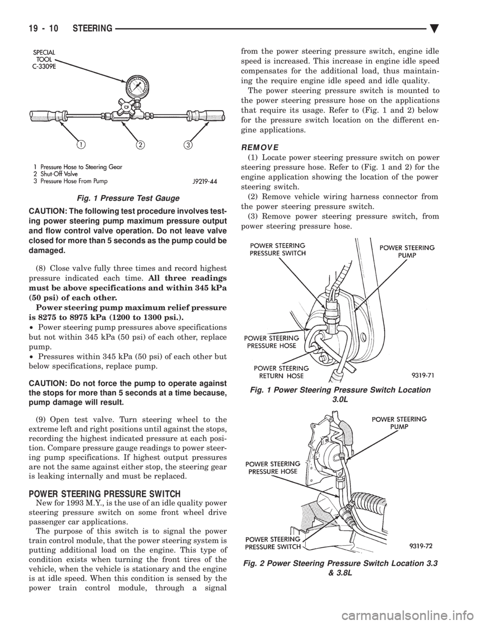
that require its usage. Refer to (Fig. 1 and 2) below
for the pressure switch location on the different en-
gine applications.
REMOVE
(1) Locate power steering pressure switch on power
steering pressure hose. Refer to (Fig. 1 and 2) for the
engine application showing the location of the power
steering switch. (2) Remove vehicle wiring harness connector from
the power steering pressure switch. (3) Remove power steering pressure switch, from
power steering pressure hose.
Fig. 1 Power Steering Pressure Switch Location 3.0L
Fig. 2 Power Steering Pressure Switch Location 3.3 & 3.8L
Fig. 1 Pressure Test Gauge
19 - 10 STEERING Ä
Page 1934 of 2438
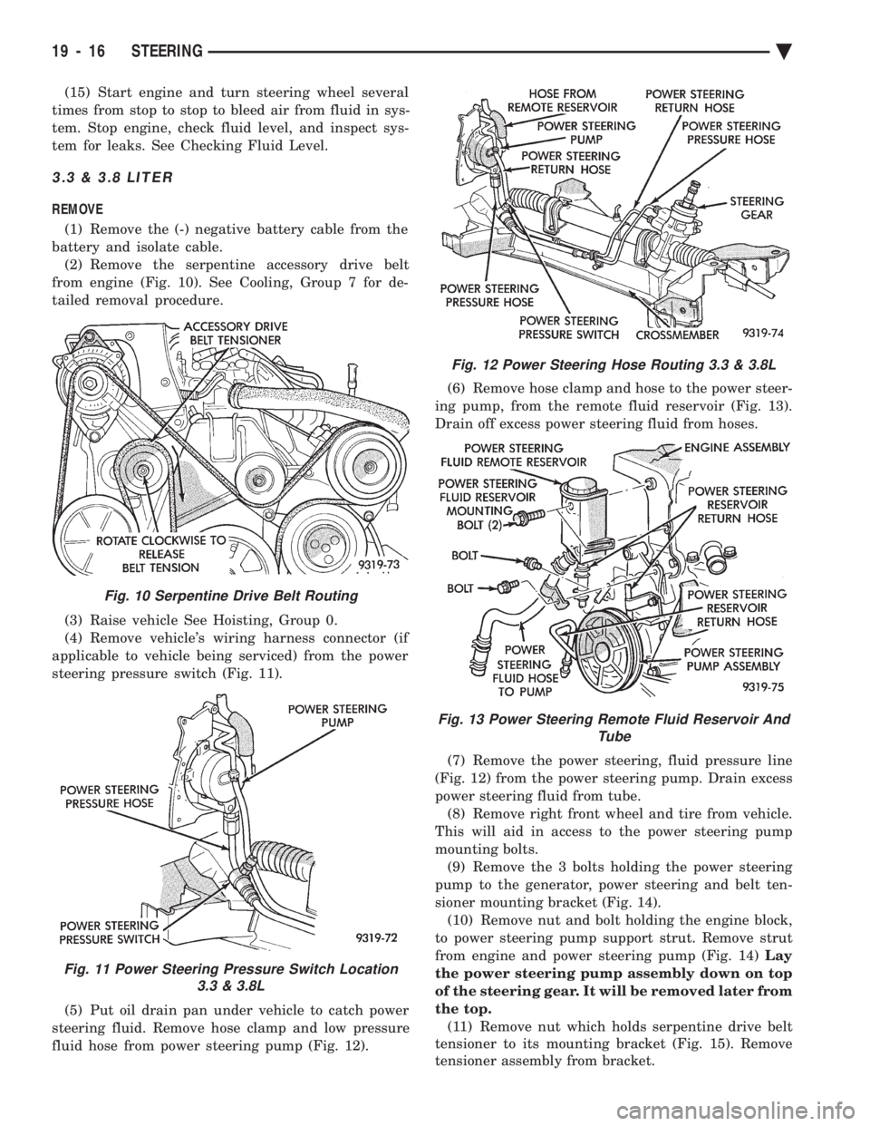
(15) Start engine and turn steering wheel several
times from stop to stop to bleed air from fluid in sys-
tem. Stop engine, check fluid level, and inspect sys-
tem for leaks. See Checking Fluid Level.
3.3 & 3.8 LITER
REMOVE
(1) Remove the (-) negative battery cable from the
battery and isolate cable. (2) Remove the serpentine accessory drive belt
from engine (Fig. 10). See Cooling, Group 7 for de-
tailed removal procedure.
(3) Raise vehicle See Hoisting, Group 0.
(4) Remove vehicle's wiring harness connector (if
applicable to vehicle being serviced) from the power
steering pressure switch (Fig. 11).
(5) Put oil drain pan under vehicle to catch power
steering fluid. Remove hose clamp and low pressure
fluid hose from power steering pump (Fig. 12). (6) Remove hose clamp and hose to the power steer-
ing pump, from the remote fluid reservoir (Fig. 13).
Drain off excess power steering fluid from hoses.
(7) Remove the power steering, fluid pressure line
(Fig. 12) from the power steering pump. Drain excess
power steering fluid from tube. (8) Remove right front wheel and tire from vehicle.
This will aid in access to the power steering pump
mounting bolts. (9) Remove the 3 bolts holding the power steering
pump to the generator, power steering and belt ten-
sioner mounting bracket (Fig. 14). (10) Remove nut and bolt holding the engine block,
to power steering pump support strut. Remove strut
from engine and power steering pump (Fig. 14) Lay
the power steering pump assembly down on top
of the steering gear. It will be removed later from
the top. (11) Remove nut which holds serpentine drive belt
tensioner to its mounting bracket (Fig. 15). Remove
tensioner assembly from bracket.
Fig. 10 Serpentine Drive Belt Routing
Fig. 11 Power Steering Pressure Switch Location 3.3 & 3.8L
Fig. 12 Power Steering Hose Routing 3.3 & 3.8L
Fig. 13 Power Steering Remote Fluid Reservoir And Tube
19 - 16 STEERING Ä
Page 1936 of 2438
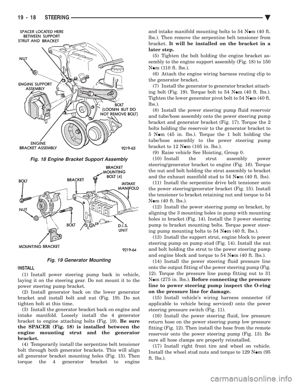
INSTALL (1) Install power steering pump back in vehicle,
laying it on the steering gear. Do not mount it to the
power steering pump bracket. (2) Install generator back on the lower generator
bracket and install bolt and nut (Fig. 19). Do not
tighten bolt at this time. (3) Install the generator bracket back on engine and
intake manifold. Loosely install the 4 generator
bracket to engine attaching bolts (Fig. 19). Be sure
the SPACER (Fig. 18) is installed between the
engine mounting strut and the generator
bracket. (4) Temporarily install the serpentine belt tensioner
bolt through both generator brackets. This will align
all generator bracket mounting holes (Fig. 15). Then
torque the 4 generator bracket to engine and intake manifold mounting bolts to 54 N
Im (40 ft.
lbs.). Then remove the serpentine belt tensioner from
bracket. It will be installed on the bracket in a
later step. (5) Tighten the bolt holding the engine bracket as-
sembly to the engine support assembly (Fig. 18) to 150
N Im (110 ft. lbs.).
(6) Attach the engine wiring harness routing clip to
the generator bracket. (7) Install the generator to generator bracket attach-
ing bolt (Fig. 19). Torque bolt to 54 N Im (40 ft. lbs.).
Tighten the lower generator pivot bolt to 54 N Im (40 ft.
lbs.). (8) Install the power steering pump fluid reservoir
and tube/hose assembly onto the power steering pump
bracket and generator bracket (Fig. 17). Torque the 2
bolts holding the reservoir to the generator bracket to
5N Im (45 in. lbs.). Torque the 1 bolt holding the
tube/hose assembly to the power steering pump
bracket to 12 N Im (105 in. lbs.).
(9) Raise vehicle See Hoisting, Group 0.
(10) Install the strut assembly power
steering/generator bracket to engine (Fig. 16). Torque
the nut and bolt holding the strut assembly to bracket
and the exhaust manifold stud to 54 N Im (40 ft. lbs).
(11) Install the serpentine drive belt tensioner onto
the power steering/generator bracket (Fig. 15). Install
the tensioner to bracket retaining nut and torque to 54
N Im (40 ft. lbs.).
(12) Install the power steering pump on bracket, by
aligning the 3 mounting holes in pump with mounting
holes in bracket (Fig. 14). Install the 3 power steering
pump to bracket mounting bolts. Torque power steer-
ing pump mounting bolts to 54 N Im (40 ft. lbs.).
(13) Install the support strut, engine block to power
steering pump on pump stud (Fig. 14). Install the nut
and bolt holding the strut to the power steering pump
and engine block and torque to 54 N Im (40 ft. lbs.).
(14) Install the power steering fluid pressure line
onto the output fitting of the power steering pump (Fig.
12). Torque the pressure line pump fitting nut to 31
N Im (275 in. lbs.). Before connecting the pressure
line to power steering pump inspect the O-ring
on the pressure line for damage. (15) Install vehicle's wiring harness connector (if
applicable to vehicle being serviced) onto the power
steering pressure switch (Fig. 11). (16) Install the power steering fluid, low pressure
return hose on the power steering pump low pressure
fitting (Fig. 12). Then install the hose from the remote
reservoir onto the power steering pump (Fig. 13). Be
sure all hose clamps are properly reinstalled. (17) Install right front tire and wheel on vehicle.
Install the wheel stud nuts and torque to 129 N Im (95
ft. lbs.).
Fig. 18 Engine Bracket Support Assembly
Fig. 19 Generator Mounting
19 - 18 STEERING Ä
Page 1945 of 2438
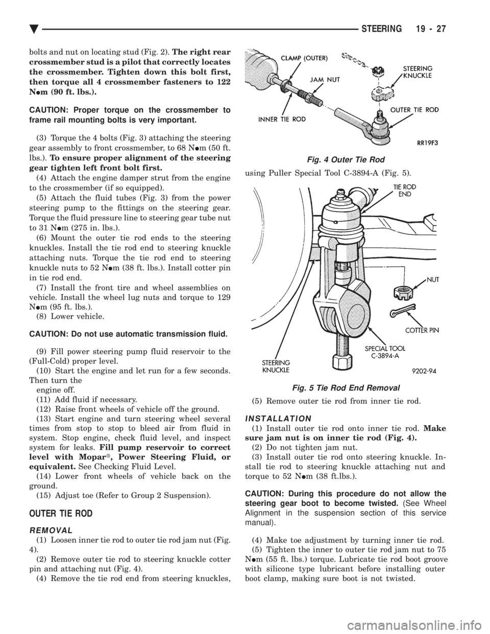
bolts and nut on locating stud (Fig. 2). The right rear
crossmember stud is a pilot that correctly locates
the crossmember. Tighten down this bolt first,
then torque all 4 crossmember fasteners to 122
N Im (90 ft. lbs.).
CAUTION: Proper torque on the crossmember to
frame rail mounting bolts is very important.
(3) Torque the 4 bolts (Fig. 3) attaching the steering
gear assembly to front crossmember, to 68 N Im (50 ft.
lbs.). To ensure proper alignment of the steering
gear tighten left front bolt first. (4) Attach the engine damper strut from the engine
to the crossmember (if so equipped). (5) Attach the fluid tubes (Fig. 3) from the power
steering pump to the fittings on the steering gear.
Torque the fluid pressure line to steering gear tube nut
to 31 N Im (275 in. lbs.).
(6) Mount the outer tie rod ends to the steering
knuckles. Install the tie rod end to steering knuckle
attaching nuts. Torque the tie rod end to steering
knuckle nuts to 52 N Im (38 ft. lbs.). Install cotter pin
in tie rod end. (7) Install the front tire and wheel assemblies on
vehicle. Install the wheel lug nuts and torque to 129
N Im (95 ft. lbs.).
(8) Lower vehicle.
CAUTION: Do not use automatic transmission fluid. (9) Fill power steering pump fluid reservoir to the
(Full-Cold) proper level. (10) Start the engine and let run for a few seconds.
Then turn the engine off.
(11) Add fluid if necessary.
(12) Raise front wheels of vehicle off the ground.
(13) Start engine and turn steering wheel several
times from stop to stop to bleed air from fluid in
system. Stop engine, check fluid level, and inspect
system for leaks. Fill pump reservoir to correct
level with Mopar t, Power Steering Fluid, or
equivalent. See Checking Fluid Level.
(14) Lower front wheels of vehicle back on the
ground. (15) Adjust toe (Refer to Group 2 Suspension).
OUTER TIE ROD
REMOVAL
(1) Loosen inner tie rod to outer tie rod jam nut (Fig.
4). (2) Remove outer tie rod to steering knuckle cotter
pin and attaching nut (Fig. 4). (4) Remove the tie rod end from steering knuckles, using Puller Special Tool C-3894-A (Fig. 5).
(5) Remove outer tie rod from inner tie rod.
INSTALLATION
(1) Install outer tie rod onto inner tie rod. Make
sure jam nut is on inner tie rod (Fig. 4). (2) Do not tighten jam nut.
(3) Install outer tie rod onto steering knuckle. In-
stall tie rod to steering knuckle attaching nut and
torque to 52 N Im (38 ft.lbs.).
CAUTION: During this procedure do not allow the
steering gear boot to become twisted. (See Wheel
Alignment in the suspension section of this service
manual).
(4) Make toe adjustment by turning inner tie rod.
(5) Tighten the inner to outer tie rod jam nut to 75
N Im (55 ft. lbs.) torque. Lubricate tie rod boot groove
with silicone type lubricant before installing outer
boot clamp, making sure boot is not twisted.
Fig. 4 Outer Tie Rod
Fig. 5 Tie Rod End Removal
Ä STEERING 19 - 27
Page 2149 of 2438
WHEELSÐTIRES
CONTENTS
page page
SPECIFICATIONS ........................ 8
TIRE SERVICE PROCEDURES .............. 1 WHEELS SERVICE PROCEDURES
........... 6
TIRE SERVICE PROCEDURES INDEX
page page
Cleaning of Tires .......................... 1
General Information ........................ 1
Pressure Gauges ......................... 2
Radial-Ply Tires ........................... 1
Repairing Leaks .......................... 3
Rotation ................................ 3 Spare TireÐCompact
...................... 1
Tire Inflation Pressures ..................... 2
Tire Noise or Vibration ..................... 3
Tire Wear Patterns ........................ 3
Tread Wear Indicators ...................... 3
GENERAL INFORMATION
Throughout this group, references may be made to a
particular vehicle by letter or number designation. A
chart showing the breakdown of these designations is
included in the Introduction Section. Tires are designed for the vehicle and provide the
best overall performance for normal operation. The
ride and handling characteristics match the vehicle's
requirements. With proper care they will give excellent
reliability traction, skid resistance and tread life. They
have load carrying capacity, when properly inflated, to
operate at loads up to the specified Maximum Vehicle
Capacity. Driving habits have more effect on tire life than any
other factor. Careful drivers will obtain, in most cases,
much greater mileage than severe or careless drivers. A
few of the driving habits which will shorten the life of
any tire are:
² Rapid acceleration and deceleration
² Severe application of brakes
² High-speed driving
² Taking turns at excessive speeds
² Striking curbs and other obstacles
Radial ply tires can be more susceptible to irregular
tread wear. It is very important to follow the tire
rotation interval shown in the section on Tire
Rotation to achieve a greater tread life potential.
RADIAL-PLY TIRES
Radial-ply tires improve handling, tread life, and
ride quality and decrease rolling resistance. Radial-ply tires must always be used in sets of four
and under no circumstances should they be used on
the front only. However, they may be mixed with temporary spare tires when necessary,
but reduced speeds are recommended. Radial-ply tires have the same load carrying capac-
ity as other types of tires of the same size. They also
use the same recommended inflation pressures.
SPARE TIREÐCOMPACT
The compact spare tire is designed for emergency
use only. The original tire should be repaired and re-
installed at the first opportunity. Refer to Owner's
Manual for complete details.
TIRE CHAINS
Tire snow chains may be used on certainmodels.
Refer to Owner's Manual for more information.
CLEANING OF TIRES
Remove protective coating on tires before delivery
of vehicle, otherwise it could cause deterioration of
tires. Remove protective coating by applying warm wa-
ter, letting it soak one minute, and then scrubbing
the coating away with a soft bristle brush. Steam cleaning may also be used for cleaning.
DO NOT use gasoline or wire brush for cleaning.
DO NOT use mineral oil or an oil-based solvent.
Ä WHEELSÐTIRES 22 - 1