1993 CHEVROLET PLYMOUTH ACCLAIM wheel bolt torque
[x] Cancel search: wheel bolt torquePage 65 of 2438
WHEEL ALIGNMENT SERVICE PROCEDURE
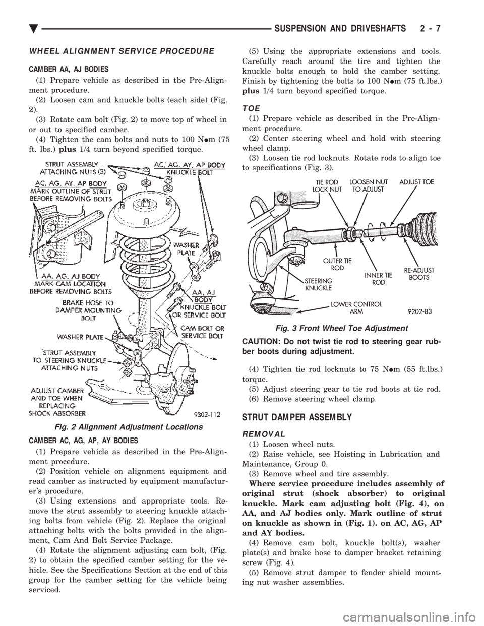
CAMBER AA, AJ BODIES (1) Prepare vehicle as described in the Pre-Align-
ment procedure. (2) Loosen cam and knuckle bolts (each side) (Fig.
2). (3) Rotate cam bolt (Fig. 2) to move top of wheel in
or out to specified camber. (4) Tighten the cam bolts and nuts to 100 N Im (75
ft. lbs.) plus1/4 turn beyond specified torque.
CAMBER AC, AG, AP, AY BODIES (1) Prepare vehicle as described in the Pre-Align-
ment procedure. (2) Position vehicle on alignment equipment and
read camber as instructed by equipment manufactur-
er's procedure. (3) Using extensions and appropriate tools. Re-
move the strut assembly to steering knuckle attach-
ing bolts from vehicle (Fig. 2). Replace the original
attaching bolts with the bolts provided in the align-
ment, Cam And Bolt Service Package. (4) Rotate the alignment adjusting cam bolt, (Fig.
2) to obtain the specified camber setting for the ve-
hicle. See the Specifications Section at the end of this
group for the camber setting for the vehicle being
serviced. (5) Using the appropriate extensions and tools.
Carefully reach around the tire and tighten the
knuckle bolts enough to hold the camber setting.
Finish by tightening the bolts to 100 N Im (75 ft.lbs.)
plus 1/4 turn beyond specified torque.
TOE
(1) Prepare vehicle as described in the Pre-Align-
ment procedure. (2) Center steering wheel and hold with steering
wheel clamp. (3) Loosen tie rod locknuts. Rotate rods to align toe
to specifications (Fig. 3).
CAUTION: Do not twist tie rod to steering gear rub-
ber boots during adjustment. (4) Tighten tie rod locknuts to 75 N Im (55 ft.lbs.)
torque. (5) Adjust steering gear to tie rod boots at tie rod.
(6) Remove steering wheel clamp.
STRUT DAMPER ASSEMBLY
REMOVAL
(1) Loosen wheel nuts.
(2) Raise vehicle, see Hoisting in Lubrication and
Maintenance, Group 0. (3) Remove wheel and tire assembly.
Where service procedure includes assembly of
original strut (shock absorber) to original
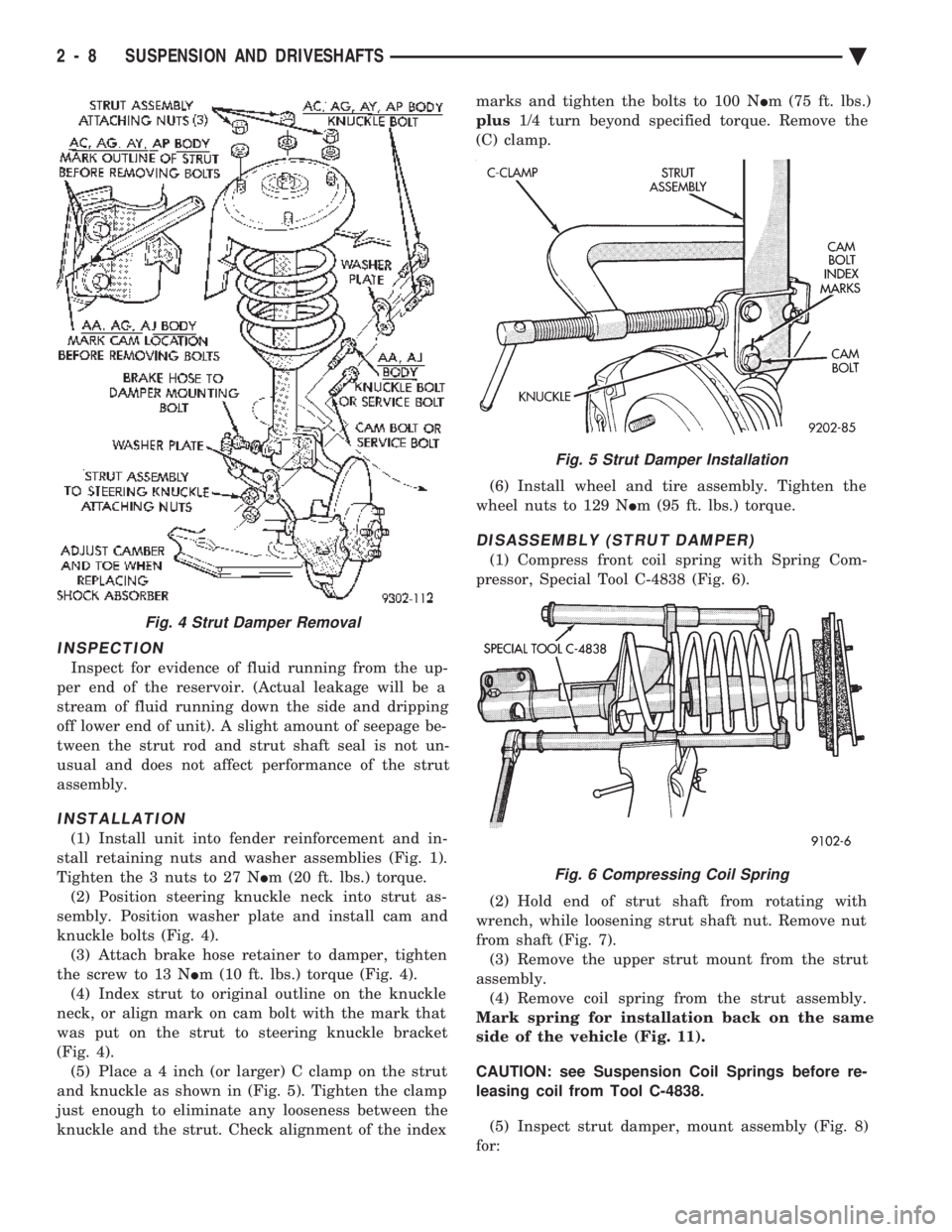
knuckle. Mark cam adjusting bolt (Fig. 4), on
AA, and AJ bodies only. Mark outline of strut
on knuckle as shown in (Fig. 1). on AC, AG, AP
and AY bodies. (4) Remove cam bolt, knuckle bolt(s), washer
plate(s) and brake hose to damper bracket retaining
screw (Fig. 4). (5) Remove strut damper to fender shield mount-
ing nut washer assemblies.
Fig. 2 Alignment Adjustment Locations
Fig. 3 Front Wheel Toe Adjustment
Ä SUSPENSION AND DRIVESHAFTS 2 - 7
Page 66 of 2438
INSPECTION
Inspect for evidence of fluid running from the up-
per end of the reservoir. (Actual leakage will be a
stream of fluid running down the side and dripping
off lower end of unit). A slight amount of seepage be-
tween the strut rod and strut shaft seal is not un-
usual and does not affect performance of the strut
assembly.
INSTALLATION
(1) Install unit into fender reinforcement and in-
stall retaining nuts and washer assemblies (Fig. 1).
Tighten the 3 nuts to 27 N Im (20 ft. lbs.) torque.
(2) Position steering knuckle neck into strut as-
sembly. Position washer plate and install cam and
knuckle bolts (Fig. 4). (3) Attach brake hose retainer to damper, tighten
the screw to 13 N Im (10 ft. lbs.) torque (Fig. 4).
(4) Index strut to original outline on the knuckle
neck, or align mark on cam bolt with the mark that
was put on the strut to steering knuckle bracket
(Fig. 4). (5) Plac e a 4 inch (or larger) C clamp on the strut
and knuckle as shown in (Fig. 5). Tighten the clamp
just enough to eliminate any looseness between the
knuckle and the strut. Check alignment of the index marks and tighten the bolts to 100 N
Im (75 ft. lbs.)
plus 1/4 turn beyond specified torque. Remove the
(C) clamp.
(6) Install wheel and tire assembly. Tighten the
wheel nuts to 129 N Im (95 ft. lbs.) torque.
DISASSEMBLY (STRUT DAMPER)
(1) Compress front coil spring with Spring Com-
pressor, Special Tool C-4838 (Fig. 6).
(2) Hold end of strut shaft from rotating with
wrench, while loosening strut shaft nut. Remove nut
from shaft (Fig. 7). (3) Remove the upper strut mount from the strut
assembly. (4) Remove coil spring from the strut assembly.
Mark spring for installation back on the same
side of the vehicle (Fig. 11).
CAUTION: see Suspension Coil Springs before re-
leasing coil from Tool C-4838.
(5) Inspect strut damper, mount assembly (Fig. 8)
for:
Fig. 4 Strut Damper Removal
Fig. 5 Strut Damper Installation
Fig. 6 Compressing Coil Spring
2 - 8 SUSPENSION AND DRIVESHAFTS Ä
Page 74 of 2438

the lower clamps and bolts. The center offset in the
sway bar should be oriented toward the front of the
vehicle (Fig. 16)(3) Position bushing retainers on lower control arms
and install bolts (Fig. 16). (4) With lower control arms raised to design height,
tighten all retainer attaching bolts to 70 N Im (50 ft.
lbs.) torque. (5) Lower vehicle.
KNUCKLE (FRONT SUSPENSION)
The front suspension knuckle (Fig. 1) provides for
steering control of the vehicle. Supports the brake
caliper and absorbs the loads exerted during vehicle
braking. It also supports the front (driving) hub and
bearing and stub axle assembly. The front suspension knuckle also provides the abil-
ity to align the front wheels of the vehicle. This is done
by allowing for front wheel camber adjustment and the
ability for front tire Toe adjustments The front suspension knuckle is not a serviceable
component. Do not attempt to straighten or repair the
front suspension knuckle in any way. Service repair or replacement of the front (drive) hub
and bearing, can be done with the front suspension
knuckle remaining on the vehicle.
REMOVAL
(1) Remove the cotter pin, hub nut lock and spring
washer from the front axle (Fig. 2). (2) Loosen hub nut while the vehicle is on the floor
with the brakes applied (Fig. 3). The hub and drive-
shaft are splined together through the knuckle
(bearing) and retained by the hub nut. (3) Raise and support the vehicle. See Hoisting in
Lubrication and Maintenance, Group 0. (4) Remove the wheel lug nuts, front tire and
wheel assembly and hub nut and washer. (5) Remove the brake caliper adapter to steering
knuckle attaching bolts and washers (Fig. 1). Re-
move the brake caliper and adapter from the steering
knuckle and braking disc. Support brake caliper/
adapter assembly using a wire hook and not by hy-
draulic hose (Fig. 4). (6) Remove the braking disc from the front hub/
bearing assembly (Fig. 5). (7) Remove the cotter pin and nut from the tie rod
end. Remove the tie rod end from the steering
knuckle arm using Puller, Special Tool C-3894-A
(Fig. 6). (8) Remove the clamp nut and bolt (Fig. 7) secur-
ing the ball joint stud into the steering knuckle. (9) Separate ball joint stud from knuckle assembly
by prying down on lower control arm. Pull knuckle
assembly out and away from driveshaft (Fig. 8).
Fig. 2 Remove Cotter Pin, Hub Nut Lock, & Spring Washer
Fig. 3 Loosen Hub Nut
Fig. 1 Front Knuckle Assembly (Typical)
2 - 16 SUSPENSION AND DRIVESHAFTS Ä
Page 77 of 2438

(7) Install the tie rod end into the arm of the steer-
ing knuckle. Install the tie rod end to steering
knuckle attaching nut, and torque to 47 N
Im (35 ft. lbs.). Install a new cotter pin into
the tie rod end (Fig. 15).
(8) Install the braking disk back on the hub and
bearing assembly (Fig. 5). (9) Install the front brake caliper and adapter back
over the braking disc and align with the adapter
mounting holes on steering knuckle (Fig. 1). Install
the caliper adapter to steering knuckle attaching
bolts and torque to 217 N Im (160 ft. lbs.).
(10) Clean all foreign matter from the threads of
the stub axle (Fig. 16). Install the washer and hub
nut onto the threads of the stub axle and tighten
nut. (11) With the vehicles brakes applied to keep front
braking disc and hub from turning. Tighten the hub
nut to a torque of 244 N Im (180 ft. lbs.) (Fig. 17).
(12) Install the spring washer, hub nut lock, and
new cotter pin. Wrap the cotter pin prongs tightly
around the hub nut lock (Fig. 18). (13) Install the front wheel and tire assembly. In-
stall the front wheel lug nuts and torque to 129 N Im
(95 ft.lbs.).
Fig. 13 Installing Knuckle Assembly
Fig. 12 Seal and Wear Sleeve Lubrication
Fig. 14 Tighten Steering Knuckle Clamp Bolt
Fig. 15 Install Tie Rod End
Ä SUSPENSION AND DRIVESHAFTS 2 - 19
Page 82 of 2438
torque. When installing guide pins, use extreme
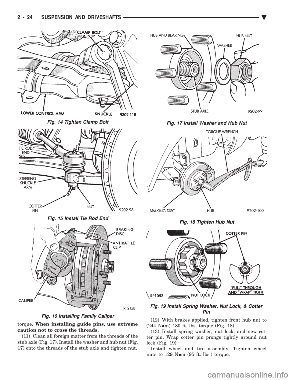
caution not to cross the threads. (11) Clean all foreign matter from the threads of the
stub axle (Fig. 17). Install the washer and hub nut (Fig.
17) onto the threads of the stub axle and tighten nut. (12) With brakes applied, tighten front hub nut to
(244 N Im) 180 ft. lbs. torque (Fig. 18).
(13) Install spring washer, nut lock, and new cot-
ter pin. Wrap cotter pin prongs tightly around nut
lock (Fig. 19). Install wheel and tire assembly. Tighten wheel
nuts to 129 N Im (95 ft. lbs.) torque.
Fig. 15 Install Tie Rod End
Fig. 16 Installing Family Caliper
Fig. 17 Install Washer and Hub Nut
Fig. 18 Tighten Hub Nut
Fig. 19 Install Spring Washer, Nut Lock, & Cotter
Pin
Fig. 14 Tighten Clamp Bolt
2 - 24 SUSPENSION AND DRIVESHAFTS Ä
Page 88 of 2438
not to allow dirt to enter or grease to leave the boot
cavity. The clamp must be removed and discarded be-
fore the rod can be inserted. After venting, install a
new Service Clamp. (See Boots Install section at the
end of this group for details).
HUB NUT INSTALL
The front wheel hub nuts use a lock and cotter pin
to maintain proper wheel bearing preload and pre-
vent the nut from backing off. Install the assembly
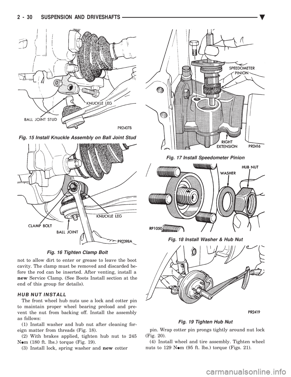
as follows: (1) Install washer and hub nut after cleaning for-
eign matter from threads (Fig. 18). (2) With brakes applied, tighten hub nut to 245
N Im (180 ft. lbs.) torque (Fig. 19).
(3) Install lock, spring washer and newcotter pin. Wrap cotter pin prongs tightly around nut lock
(Fig. 20). (4) Install wheel and tire assembly. Tighten wheel
nuts to 129 N Im (95 ft. lbs.) torque (Figs. 21).
Fig. 15 Install Knuckle Assembly on Ball Joint Stud
Fig. 16 Tighten Clamp Bolt
Fig. 17 Install Speedometer Pinion
Fig. 18 Install Washer & Hub Nut
Fig. 19 Tighten Hub Nut
2 - 30 SUSPENSION AND DRIVESHAFTS Ä
Page 109 of 2438
to the road surface. While being able to twist as one
wheel moves vertically with respect to the other.Roll resistance is provided partly by the axle's re-
sistance to twist. But primarily by a torque tube or
rod (depending on the suspension option called for)
running through the channel and attached rigidly to
its end plates by welding. Because the torque tube/
rod is an integral part of the axle assembly, it cannot
be individually replaced. The spindles are bolted to the axle end (spindle
mounting) plates and can be individually replaced if
required. Rear wheel alignment changes require the
use of shims between the spindle and axle end plates.
SHOCK ABSORBERS
REMOVAL
(1) Raise vehicle, see Hoisting, Group 0.
(2) Support axle and remove wheel and tire assem-
bly. (3) If equipped with air shocks, disconnect air
lines. (4) Remove upper and lower shock absorber fasten-
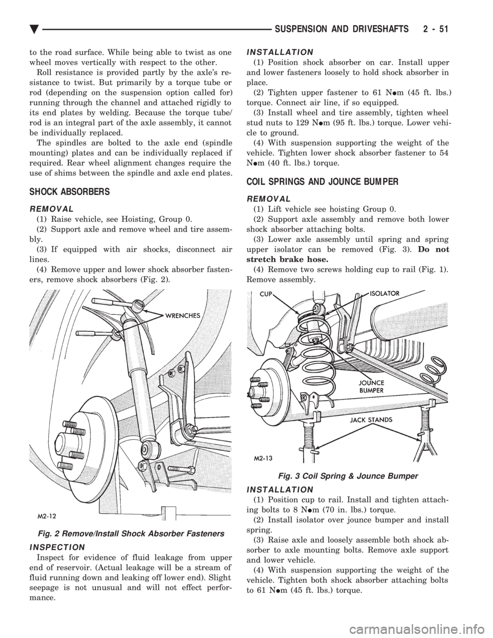
ers, remove shock absorbers (Fig. 2).
INSPECTION
Inspect for evidence of fluid leakage from upper
end of reservoir. (Actual leakage will be a stream of
fluid running down and leaking off lower end). Slight
seepage is not unusual and will not effect perfor-
mance.
INSTALLATION
(1) Position shock absorber on car. Install upper
and lower fasteners loosely to hold shock absorber in
place. (2) Tighten upper fastener to 61 N Im (45 ft. lbs.)
torque. Connect air line, if so equipped. (3) Install wheel and tire assembly, tighten wheel
stud nuts to 129 N Im (95 ft. lbs.) torque. Lower vehi-
cle to ground. (4) With suspension supporting the weight of the
vehicle. Tighten lower shock absorber fastener to 54
N Im (40 ft. lbs.) torque.
COIL SPRINGS AND JOUNCE BUMPER
REMOVAL
(1) Lift vehicle see hoisting Group 0.
(2) Support axle assembly and remove both lower
shock absorber attaching bolts. (3) Lower axle assembly until spring and spring
upper isolator can be removed (Fig. 3). Do not
stretch brake hose. (4) Remove two screws holding cup to rail (Fig. 1).
Remove assembly.
INSTALLATION
(1) Position cup to rail. Install and tighten attach-
ing bolts to 8 N Im (70 in. lbs.) torque.
(2) Install isolator over jounce bumper and install
spring. (3) Raise axle and loosely assemble both shock ab-
sorber to axle mounting bolts. Remove axle support
and lower vehicle. (4) With suspension supporting the weight of the
vehicle. Tighten both shock absorber attaching bolts
to 61 N Im (45 ft. lbs.) torque.
Fig. 2 Remove/Install Shock Absorber Fasteners
Fig. 3 Coil Spring & Jounce Bumper
Ä SUSPENSION AND DRIVESHAFTS 2 - 51
Page 115 of 2438
REAR AXLE ASSEMBLY
REMOVE
(1) Raise vehicle (see Hoisting, Group 0). Support
axle with jack stands and remove wheel and tire as-
sembly. (2) Separate park brake cable at connector. Detach
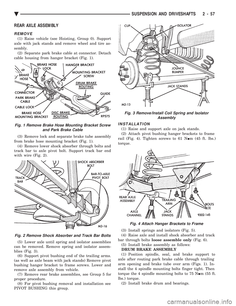
cable housing from hanger bracket (Fig. 1).
(3) Remove lock and separate brake tube assembly
from brake hose mounting bracket (Fig. 1). (4) Remove lower shock absorber through bolts and
track bar to axle pivot bolt. Support track bar end
with wire (Fig. 2).
(5) Lower axle until spring and isolator assemblies
can be removed. Remove spring and isolator assem-
blies (Fig. 3). (6) Support pivot bushing end of the trailing arms.
(as well as axle beam with jack stands) Remove pivot
bushing hanger bracket to frame screws. Lower and
remove axle assembly from vehicle. (7) Remove rear brake assemblies, see Group 5 for
proper procedure. (8) For pivot bushing removal and installation see
PIVOT BUSHING this group.
INSTALLATION
(1) Raise and support axle on jack stands.
(2) Attach pivot bushing hanger brackets to frame
rail (Fig. 4). Tighten screws to 61 N Im (45 ft. lbs.)
torque.
(3) Install springs and isolators (Fig. 5).
(4) Raise axle and install shock absorber and track
bar through bolts loose assemble only (Fig. 6).
(5) Install brake assembly as follows:
DRUM BRAKE ASSEMBLY
(1) Position spindle, seal, and brake support to
axle after routing park brake cable through trailing
arm opening and brake tube over arm (Figs. 1). In-
stall the 4 spindle mounting bolts finger tight. Then
torque the 4 spindle mounting bolts to 75 N Im (55 ft.
lbs.) torque. (2) Install brake drum and bearings.Fig. 1 Remove Brake Hose Mounting Bracket Screw and Park Brake Cable
Fig. 2 Remove Shock Absorber and Track Bar Bolts
Fig. 3 Remove/Install Coil Spring and Isolator Assembly
Fig. 4 Attach Hanger Brackets to Frame
Ä SUSPENSION AND DRIVESHAFTS 2 - 57