1993 CHEVROLET PLYMOUTH ACCLAIM wheel bolt torque
[x] Cancel search: wheel bolt torquePage 1678 of 2438
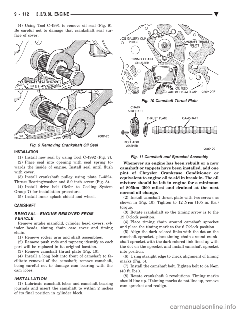
(4) Using Tool C-4991 to remove oil seal (Fig. 9).
Be careful not to damage that crankshaft seal sur-
face of cover.
INSTALLATION (1) Install new seal by using Tool C-4992 (Fig. 7).
(2) Place seal into opening with seal spring to-
wards the inside of engine. Install seal until flush
with cover. (3) Install crankshaft pulley using plate L-4524.
Thrust Bearing/washer and 5.9 inch screw (Fig. 8). (4) Install drive belt (Refer to Cooling System
Group 7) for installation procedure. (5) Install inner splash shield and wheel.
CAMSHAFT
REMOVALÐENGINE REMOVED FROM VEHICLE
Remove intake manifold, cylinder head covers, cyl-
inder heads, timing chain case cover and timing
chain. (1) Remove rocker arm and shaft assemblies.
(2) Remove push rods and tappets; identify so each
part will be replaced in its original location. (3) Remove camshaft thrust plate (Fig. 10).
(4) Install a long bolt into front of camshaft to fa-
cilitate removal of the camshaft; remove camshaft,
being careful not to damage cam bearing with the
cam lobes.
INSTALLATION
(1) Lubricate camshaft lobes and camshaft bearing
journals and insert the camshaft to within 2 inches
of its final position in cylinder block. Whenever an engine has been rebuilt or a new
camshaft or tappets have been installed, add one
pint of Chrysler Crankcase Conditioner or
equivalent to engine oil to aid in break in. The oil
mixture should be left in engine for a minimum
of 805km (500 miles) and drained at the next
normal oil change. (2) Install camshaft thrust plate with two screws as
shown in (Fig. 10). Tighten to 12 N Im (105 in. lbs.)
torque. (3) Rotate crankshaft so the timing arrow is to the
12 O'clock position. (4) Place timing chain around camshaft sprocket
and place the timing mark to the 6 O'clock position. (5) Align the dark colored links with the dot on the
camshaft sprocket, place timing chain around crank-
shaft sprocket with the dark colored link lined up with
the dot on the sprocket and install camshaft sprocket
into position. (6) Using straight edge to check alignment of timing
marks (Fig. 5). (7) Install the camshaft bolt. Tighten bolt to 54 N Im
(40 ft. lbs.). (8) Rotate crankshaft 2 revolutions. Timing marks
should line up. If timing marks do not line up, remove
cam sprocket and realign.
Fig. 9 Removing Crankshaft Oil Seal
Fig. 10 Camshaft Thrust Plate
Fig. 11 Camshaft and Sprocket Assembly
9 - 112 3.3/3.8L ENGINE Ä
Page 1709 of 2438
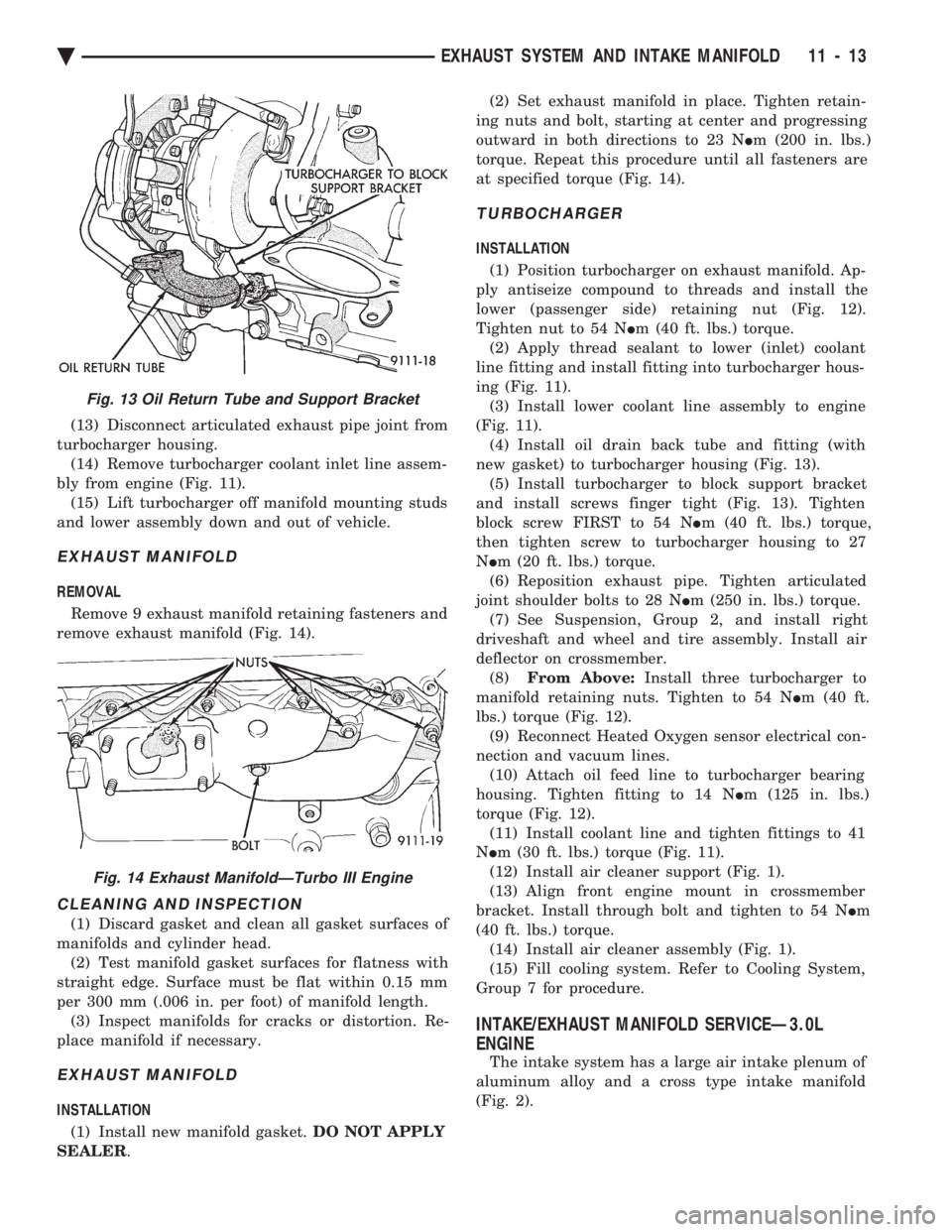
(13) Disconnect articulated exhaust pipe joint from
turbocharger housing. (14) Remove turbocharger coolant inlet line assem-
bly from engine (Fig. 11). (15) Lift turbocharger off manifold mounting studs
and lower assembly down and out of vehicle.
EXHAUST MANIFOLD
REMOVAL
Remove 9 exhaust manifold retaining fasteners and
remove exhaust manifold (Fig. 14).
CLEANING AND INSPECTION
(1) Discard gasket and clean all gasket surfaces of
manifolds and cylinder head. (2) Test manifold gasket surfaces for flatness with
straight edge. Surface must be flat within 0.15 mm
per 300 mm (.006 in. per foot) of manifold length. (3) Inspect manifolds for cracks or distortion. Re-
place manifold if necessary.
EXHAUST MANIFOLD
INSTALLATION
(1) Install new manifold gasket. DO NOT APPLY
SEALER . (2) Set exhaust manifold in place. Tighten retain-
ing nuts and bolt, starting at center and progressing
outward in both directions to 23 N Im (200 in. lbs.)
torque. Repeat this procedure until all fasteners are
at specified torque (Fig. 14).
TURBOCHARGER
INSTALLATION
(1) Position turbocharger on exhaust manifold. Ap-
ply antiseize compound to threads and install the
lower (passenger side) retaining nut (Fig. 12).
Tighten nut to 54 N Im (40 ft. lbs.) torque.
(2) Apply thread sealant to lower (inlet) coolant
line fitting and install fitting into turbocharger hous-
ing (Fig. 11). (3) Install lower coolant line assembly to engine
(Fig. 11). (4) Install oil drain back tube and fitting (with
new gasket) to turbocharger housing (Fig. 13). (5) Install turbocharger to block support bracket
and install screws finger tight (Fig. 13). Tighten
block screw FIRST to 54 N Im (40 ft. lbs.) torque,
then tighten screw to turbocharger housing to 27
N Im (20 ft. lbs.) torque.
(6) Reposition exhaust pipe. Tighten articulated
joint shoulder bolts to 28 N Im (250 in. lbs.) torque.
(7) See Suspension, Group 2, and install right
driveshaft and wheel and tire assembly. Install air
deflector on crossmember. (8) From Above: Install three turbocharger to
manifold retaining nuts. Tighten to 54 N Im (40 ft.
lbs.) torque (Fig. 12). (9) Reconnect Heated Oxygen sensor electrical con-
nection and vacuum lines. (10) Attach oil feed line to turbocharger bearing
housing. Tighten fitting to 14 N Im (125 in. lbs.)
torque (Fig. 12). (11) Install coolant line and tighten fittings to 41
N Im (30 ft. lbs.) torque (Fig. 11).
(12) Install air cleaner support (Fig. 1).
(13) Align front engine mount in crossmember
bracket. Install through bolt and tighten to 54 N Im
(40 ft. lbs.) torque. (14) Install air cleaner assembly (Fig. 1).
(15) Fill cooling system. Refer to Cooling System,
Group 7 for procedure.
INTAKE/EXHAUST MANIFOLD SERVICEÐ3.0L
ENGINE
The intake system has a large air intake plenum of
aluminum alloy and a cross type intake manifold
(Fig. 2).
Fig. 13 Oil Return Tube and Support Bracket
Fig. 14 Exhaust ManifoldÐTurbo III Engine
Ä EXHAUST SYSTEM AND INTAKE MANIFOLD 11 - 13
Page 1929 of 2438
INSTALL
(1) Install power steering pressure switch into fit-
ting on power steering pressure hose by hand until
fully seated. Then torque power steering pressure
switch to 12 N Im (106 in. lbs.).
(2) Install vehicle wiring harness connector onto
power steering pressure switch. Be sure latch on wir-
ing harness connector is fully engaged with locking
tab on power steering pressure switch.
CAUTION: Do not use automatic transmission fluid
in power steering system. Only use Mopar T, Power
Steering Fluid, or equivalent.
(3) Fill power steering pump reservoir to correct
fluid level. (4) Connect negative cable back on negative post of
battery. (5) Start engine and turn steering wheel several
times from stop to stop to bleed air from fluid in sys-
tem. Stop engine, check fluid level, and inspect sys-
tem for leaks. See Checking Fluid Level.
POWER STEERING HOSES
Service all power steering hoses with the vehicle
raised on a hoist. Cap all open ends of hoses, power
steering pump fittings and steering gear ports to pre-
vent entry of foreign material into the components.
WARNING: POWER STEERING OIL, ENGINE PARTS
AND EXHAUST SYSTEM MAY BE EXTREMELY HOT
IF ENGINE HAS BEEN RUNNING. DO NOT START
ENGINE WITH ANY LOOSE OR DISCONNECTED
HOSES. DO NOT ALLOW HOSES TO TOUCH HOT
EXHAUST MANIFOLD OR CATALYST.
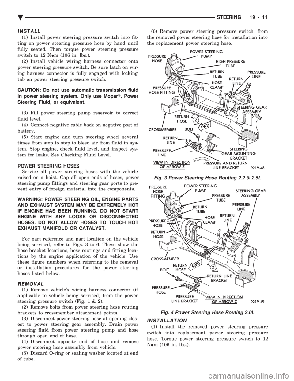
For part reference and part location on the vehicle
being serviced, refer to Figs. 3 to 6. These show the
hose bracket locations, hose routings and fitting loca-
tions by the engine application of the vehicle. Use
these figure numbers when referring to the removal
or installation procedures for the power steering
hoses listed below.
REMOVAL
(1) Remove vehicle's wiring harness connector (if
applicable to vehicle being serviced) from the power
steering pressure switch (Fig .1&2).
(2) Remove bolts from power steering hose routing
brackets to crossmember attachment points. (3) Disconnect power steering hose at opening clos-
est to power steering gear assembly. Drain power
steering fluid from power steering pump and hose
through open end of hose. (4) Disconnect opposite end of hose and remove
power steering hose assembly from vehicle. (5) Discard O-ring or sealing washer located at end
of tube. (6) Remove power steering pressure switch, from
the removed power steering hose for installation into
the replacement power steering hose.
INSTALLATION
(1) Install the removed power steering pressure
switch into replacement power steering pressure
hose. Torque power steering pressure switch to 12
N Im (106 in. lbs.).
Fig. 3 Power Steering Hose Routing 2.2 & 2.5L
Fig. 4 Power Steering Hose Routing 3.0L
Ä STEERING 19 - 11
Page 1936 of 2438
INSTALL (1) Install power steering pump back in vehicle,
laying it on the steering gear. Do not mount it to the
power steering pump bracket. (2) Install generator back on the lower generator
bracket and install bolt and nut (Fig. 19). Do not
tighten bolt at this time. (3) Install the generator bracket back on engine and
intake manifold. Loosely install the 4 generator
bracket to engine attaching bolts (Fig. 19). Be sure
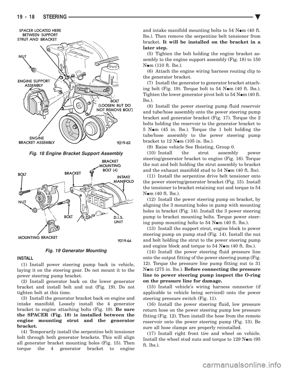
the SPACER (Fig. 18) is installed between the
engine mounting strut and the generator
bracket. (4) Temporarily install the serpentine belt tensioner
bolt through both generator brackets. This will align
all generator bracket mounting holes (Fig. 15). Then
torque the 4 generator bracket to engine and intake manifold mounting bolts to 54 N
Im (40 ft.
lbs.). Then remove the serpentine belt tensioner from
bracket. It will be installed on the bracket in a
later step. (5) Tighten the bolt holding the engine bracket as-
sembly to the engine support assembly (Fig. 18) to 150
N Im (110 ft. lbs.).
(6) Attach the engine wiring harness routing clip to
the generator bracket. (7) Install the generator to generator bracket attach-
ing bolt (Fig. 19). Torque bolt to 54 N Im (40 ft. lbs.).
Tighten the lower generator pivot bolt to 54 N Im (40 ft.
lbs.). (8) Install the power steering pump fluid reservoir
and tube/hose assembly onto the power steering pump
bracket and generator bracket (Fig. 17). Torque the 2
bolts holding the reservoir to the generator bracket to
5N Im (45 in. lbs.). Torque the 1 bolt holding the
tube/hose assembly to the power steering pump
bracket to 12 N Im (105 in. lbs.).
(9) Raise vehicle See Hoisting, Group 0.
(10) Install the strut assembly power
steering/generator bracket to engine (Fig. 16). Torque
the nut and bolt holding the strut assembly to bracket
and the exhaust manifold stud to 54 N Im (40 ft. lbs).
(11) Install the serpentine drive belt tensioner onto
the power steering/generator bracket (Fig. 15). Install
the tensioner to bracket retaining nut and torque to 54
N Im (40 ft. lbs.).
(12) Install the power steering pump on bracket, by
aligning the 3 mounting holes in pump with mounting
holes in bracket (Fig. 14). Install the 3 power steering
pump to bracket mounting bolts. Torque power steer-
ing pump mounting bolts to 54 N Im (40 ft. lbs.).
(13) Install the support strut, engine block to power
steering pump on pump stud (Fig. 14). Install the nut
and bolt holding the strut to the power steering pump
and engine block and torque to 54 N Im (40 ft. lbs.).
(14) Install the power steering fluid pressure line
onto the output fitting of the power steering pump (Fig.
12). Torque the pressure line pump fitting nut to 31
N Im (275 in. lbs.). Before connecting the pressure
line to power steering pump inspect the O-ring
on the pressure line for damage. (15) Install vehicle's wiring harness connector (if
applicable to vehicle being serviced) onto the power
steering pressure switch (Fig. 11). (16) Install the power steering fluid, low pressure
return hose on the power steering pump low pressure
fitting (Fig. 12). Then install the hose from the remote
reservoir onto the power steering pump (Fig. 13). Be
sure all hose clamps are properly reinstalled. (17) Install right front tire and wheel on vehicle.
Install the wheel stud nuts and torque to 129 N Im (95
ft. lbs.).
Fig. 18 Engine Bracket Support Assembly
Fig. 19 Generator Mounting
19 - 18 STEERING Ä
Page 1938 of 2438
INSTALL (1) Install the power steering pump back into the
vehicle in the reverse order of removal, between cyl-
inder head and dash panel (Fig. 20). (2) Install the wiring harness connector back on
the H-valve located on the air conditioning fluid
lines (Fig. 20). (3) Raise vehicle See Hoisting, Group 0.
(4) Install the power steering pump on its mount-
ing bracket, and the hose locator bracket. Install the
bolt/stud and 2 bolts attaching the power steering
pump to its mounting bracket, and the bolts attach-
ing the hose locator bracket (Fig. 19). Torque all fas-
teners to 31 N Im (280 in. lbs.).
(5) Install the power steering fluid pressure hose,
banjo bolt and seal washer onto power steering pump
(Fig. 4). Pressure hose is to be installed so it is
routed to the left of the hose locator bracket (Fig.
19). Torque the banjo bolt to 31 N Im (275 in. lbs.).
Inspect the O-rings on the banjo bolt to ensure
they are not damaged and located correctly. (6) Install the low pressure fluid return hose from
the power steering pump back on the steel tube on
the steering gear (Fig. 4). Install hose clamp, be sure
the hose clamp is installed past the retaining bead
the steel tube. Install the hose routing clip on the
power steering pump bolt/stud, install clip retaining
nut and tighten. (7) Install the serpentine accessory drive belt (Fig.
18). Be sure the belt is correctly installed and
aligned on all pulleys before starting engine. (8) Install the right front underhood splash shield.
CAUTION: Do not use automatic transmission fluid
in power steering system. Only use Mopar T, Power
Steering Fluid, or equivalent.
(9) Fill power steering pump reservoir to correct
fluid level. (10) Connect the negative battery cable on the
negative battery post. (11) Start engine and turn steering wheel several
times from stop to stop to bleed air from fluid in sys-
tem. Stop engine, check fluid level, and inspect sys-
tem for leaks. See Checking Fluid Level.
POWER STEERING PUMP PULLEY SERVICE
SAGINAW VANE SUBMERGED PUMP
REMOVE
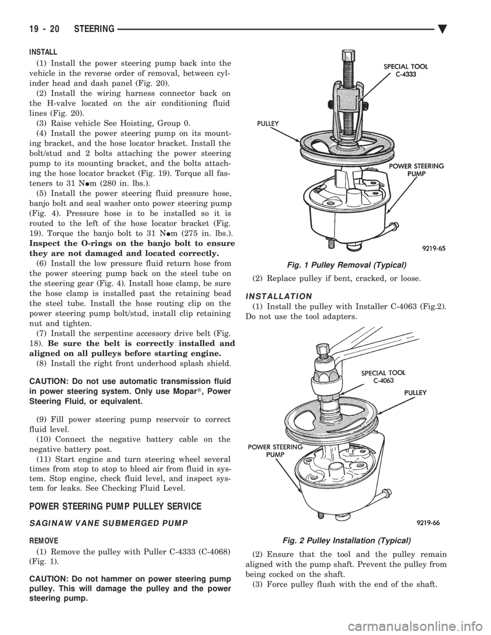
(1) Remove the pulley with Puller C-4333 (C-4068)
(Fig. 1).
CAUTION: Do not hammer on power steering pump
pulley. This will damage the pulley and the power
steering pump. (2) Replace pulley if bent, cracked, or loose.
INSTALLATION
(1) Install the pulley with Installer C-4063 (Fig.2).
Do not use the tool adapters.
(2) Ensure that the tool and the pulley remain
aligned with the pump shaft. Prevent the pulley from
being cocked on the shaft. (3) Force pulley flush with the end of the shaft.
Fig. 1 Pulley Removal (Typical)
Fig. 2 Pulley Installation (Typical)
19 - 20 STEERING Ä
Page 1945 of 2438
bolts and nut on locating stud (Fig. 2). The right rear
crossmember stud is a pilot that correctly locates
the crossmember. Tighten down this bolt first,
then torque all 4 crossmember fasteners to 122
N Im (90 ft. lbs.).
CAUTION: Proper torque on the crossmember to
frame rail mounting bolts is very important.
(3) Torque the 4 bolts (Fig. 3) attaching the steering
gear assembly to front crossmember, to 68 N Im (50 ft.
lbs.). To ensure proper alignment of the steering
gear tighten left front bolt first. (4) Attach the engine damper strut from the engine
to the crossmember (if so equipped). (5) Attach the fluid tubes (Fig. 3) from the power
steering pump to the fittings on the steering gear.
Torque the fluid pressure line to steering gear tube nut
to 31 N Im (275 in. lbs.).
(6) Mount the outer tie rod ends to the steering
knuckles. Install the tie rod end to steering knuckle
attaching nuts. Torque the tie rod end to steering
knuckle nuts to 52 N Im (38 ft. lbs.). Install cotter pin
in tie rod end. (7) Install the front tire and wheel assemblies on
vehicle. Install the wheel lug nuts and torque to 129
N Im (95 ft. lbs.).
(8) Lower vehicle.
CAUTION: Do not use automatic transmission fluid. (9) Fill power steering pump fluid reservoir to the
(Full-Cold) proper level. (10) Start the engine and let run for a few seconds.
Then turn the engine off.
(11) Add fluid if necessary.
(12) Raise front wheels of vehicle off the ground.
(13) Start engine and turn steering wheel several
times from stop to stop to bleed air from fluid in
system. Stop engine, check fluid level, and inspect
system for leaks. Fill pump reservoir to correct
level with Mopar t, Power Steering Fluid, or
equivalent. See Checking Fluid Level.
(14) Lower front wheels of vehicle back on the
ground. (15) Adjust toe (Refer to Group 2 Suspension).
OUTER TIE ROD
REMOVAL
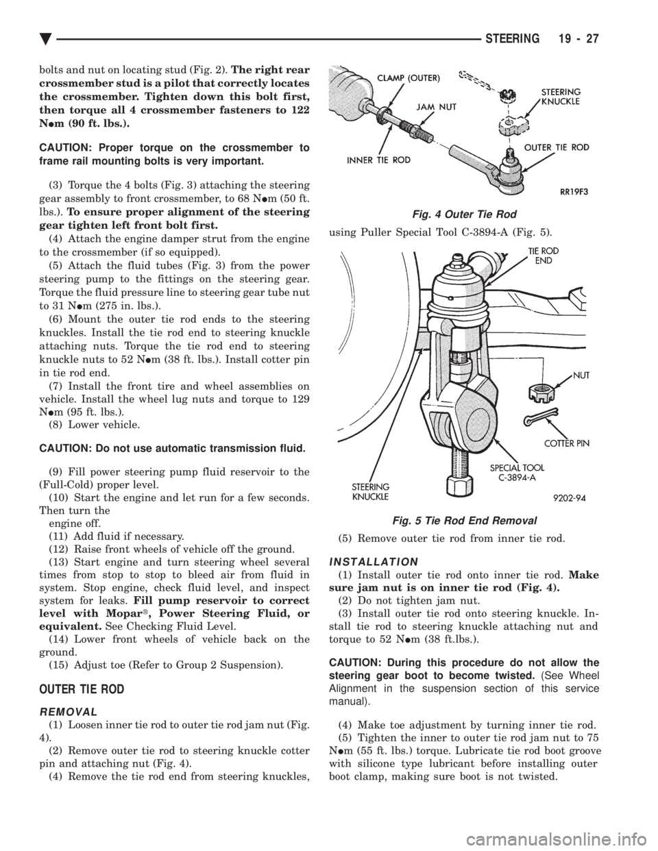
(1) Loosen inner tie rod to outer tie rod jam nut (Fig.
4). (2) Remove outer tie rod to steering knuckle cotter
pin and attaching nut (Fig. 4). (4) Remove the tie rod end from steering knuckles, using Puller Special Tool C-3894-A (Fig. 5).
(5) Remove outer tie rod from inner tie rod.
INSTALLATION
(1) Install outer tie rod onto inner tie rod. Make
sure jam nut is on inner tie rod (Fig. 4). (2) Do not tighten jam nut.
(3) Install outer tie rod onto steering knuckle. In-
stall tie rod to steering knuckle attaching nut and
torque to 52 N Im (38 ft.lbs.).
CAUTION: During this procedure do not allow the
steering gear boot to become twisted. (See Wheel
Alignment in the suspension section of this service
manual).
(4) Make toe adjustment by turning inner tie rod.
(5) Tighten the inner to outer tie rod jam nut to 75
N Im (55 ft. lbs.) torque. Lubricate tie rod boot groove
with silicone type lubricant before installing outer
boot clamp, making sure boot is not twisted.
Fig. 4 Outer Tie Rod
Fig. 5 Tie Rod End Removal
Ä STEERING 19 - 27
Page 1951 of 2438
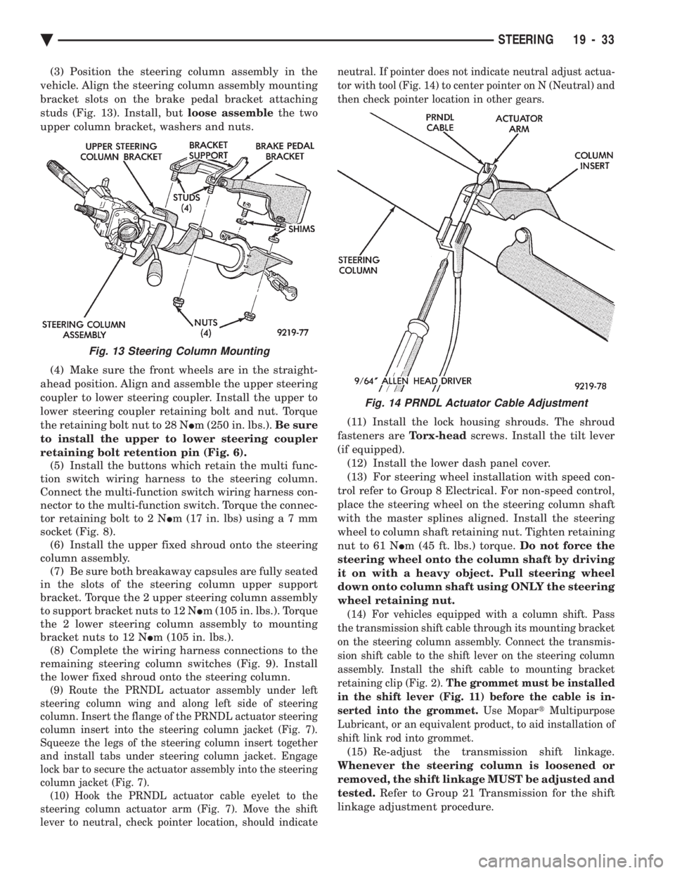
(3) Position the steering column assembly in the
vehicle. Align the steering column assembly mounting
bracket slots on the brake pedal bracket attaching
studs (Fig. 13). Install, but loose assemblethe two
upper column bracket, washers and nuts.
(4) Make sure the front wheels are in the straight-
ahead position. Align and assemble the upper steering
coupler to lower steering coupler. Install the upper to
lower steering coupler retaining bolt and nut. Torque
the retaining bolt nut to 28 N Im (250 in. lbs.). Be sure
to install the upper to lower steering coupler
retaining bolt retention pin (Fig. 6). (5) Install the buttons which retain the multi func-
tion switch wiring harness to the steering column.
Connect the multi-function switch wiring harness con-
nector to the multi-function switch. Torque the connec-
tor retaining bolt to 2 N Im (17 in. lbs) usin ga7mm
socket (Fig. 8). (6) Install the upper fixed shroud onto the steering
column assembly. (7) Be sure both breakaway capsules are fully seated
in the slots of the steering column upper support
bracket. Torque the 2 upper steering column assembly
to support bracket nuts to 12 N Im (105 in. lbs.). Torque
the 2 lower steering column assembly to mounting
bracket nuts to 12 N Im (105 in. lbs.).
(8) Complete the wiring harness connections to the
remaining steering column switches (Fig. 9). Install
the lower fixed shroud onto the steering column.
(9) Route the PRNDL actuator assembly under left
steering column wing and along left side of steering
column. Insert the flange of the PRNDL actuator steering
column insert into the steering column jacket (Fig. 7).
Squeeze the legs of the steering column insert together
and install tabs under steering column jacket. Engage
lock bar to secure the actuator assembly into the steering
column jacket (Fig. 7). (10) Hook the PRNDL actuator cable eyelet to the
steering column actuator arm (Fig. 7). Move the shift
lever to neutral, check pointer location, should indicate neutral. If pointer does not indicate neutral adjust actua-
tor with tool (Fig. 14) to center pointer on N (Neutral) and
then check pointer location in other gears.
(11) Install the lock housing shrouds. The shroud
fasteners are Torx-headscrews. Install the tilt lever
(if equipped). (12) Install the lower dash panel cover.
(13) For steering wheel installation with speed con-
trol refer to Group 8 Electrical. For non-speed control,
place the steering wheel on the steering column shaft
with the master splines aligned. Install the steering
wheel to column shaft retaining nut. Tighten retaining
nut to 61 N Im (45 ft. lbs.) torque. Do not force the
steering wheel onto the column shaft by driving
it on with a heavy object. Pull steering wheel
down onto column shaft using ONLY the steering
wheel retaining nut.
(14) For vehicles equipped with a column shift. Pass
the transmission shift cable through its mounting bracket
on the steering column assembly. Connect the transmis-
sion shift cable to the shift lever on the steering column
assembly. Install the shift cable to mounting bracket
retaining clip (Fig. 2). The grommet must be installed
in the shift lever (Fig. 11) before the cable is in-
serted into the grommet. Use MopartMultipurpose
Lubricant, or an equivalent product, to aid installation of
shift link rod into grommet.
(15) Re-adjust the transmission shift linkage.
Whenever the steering column is loosened or
removed, the shift linkage MUST be adjusted and
tested. Refer to Group 21 Transmission for the shift
linkage adjustment procedure.
Fig. 13 Steering Column Mounting
Fig. 14 PRNDL Actuator Cable Adjustment
Ä STEERING 19 - 33
Page 1964 of 2438
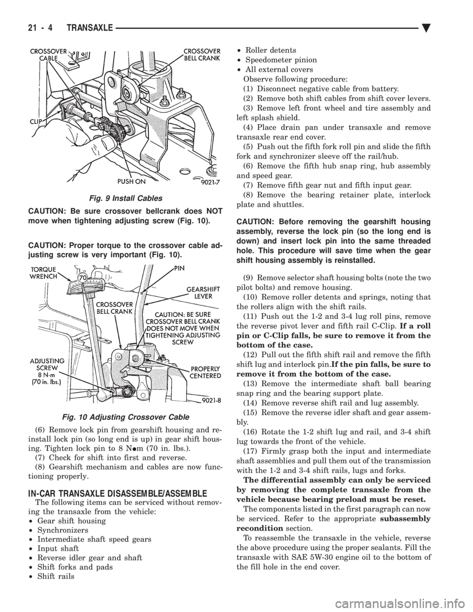
CAUTION: Be sure crossover bellcrank does NOT
move when tightening adjusting screw (Fig. 10).
CAUTION: Proper torque to the crossover cable ad-
justing screw is very important (Fig. 10).
(6) Remove lock pin from gearshift housing and re-
install lock pin (so long end is up) in gear shift hous-
ing. Tighten lock pin to 8 N Im (70 in. lbs.).
(7) Check for shift into first and reverse.
(8) Gearshift mechanism and cables are now func-
tioning properly.
IN-CAR TRANSAXLE DISASSEMBLE/ASSEMBLE
The following items can be serviced without remov-
ing the transaxle from the vehicle:
² Gear shift housing
² Synchronizers
² Intermediate shaft speed gears
² Input shaft
² Reverse idler gear and shaft
² Shift forks and pads
² Shift rails ²
Roller detents
² Speedometer pinion
² All external covers
Observe following procedure:
(1) Disconnect negative cable from battery.
(2) Remove both shift cables from shift cover levers.
(3) Remove left front wheel and tire assembly and
left splash shield. (4) Place drain pan under transaxle and remove
transaxle rear end cover. (5) Push out the fifth fork roll pin and slide the fifth
fork and synchronizer sleeve off the rail/hub. (6) Remove the fifth hub snap ring, hub assembly
and speed gear. (7) Remove fifth gear nut and fifth input gear.
(8) Remove the bearing retainer plate, interlock
plate and shuttles.
CAUTION: Before removing the gearshift housing
assembly, reverse the lock pin (so the long end is
down) and insert lock pin into the same threaded
hole. This procedure will save time when the gear
shift housing assembly is reinstalled. (9) Remove selector shaft housing bolts (note the two
pilot bolts) and remove housing. (10) Remove roller detents and springs, noting that
the rollers align with the shift rails. (11) Push out the 1-2 and 3-4 lug roll pins, remove
the reverse pivot lever and fifth rail C-Clip. If a roll
pin or C-Clip falls, be sure to remove it from the
bottom of the case. (12) Pull out the fifth shift rail and remove the fifth
shift lug and interlock pin. If the pin falls, be sure to
remove it from the bottom of the case. (13) Remove the intermediate shaft ball bearing
snap ring and the bearing support plate. (14) Remove reverse shift rail and lug assembly.
(15) Remove the reverse idler shaft and gear assem-
bly. (16) Rotate the 1-2 shift lug and rail, and 3-4 shift
lug towards the front of the vehicle. (17) Firmly grasp both the input and intermediate
shaft assemblies and pull them out of the transmission
with the 1-2 and 3-4 shift rails, lugs and forks. The differential assembly can only be serviced
by removing the complete transaxle from the
vehicle because bearing preload must be reset. The components listed in the first paragraph can now
be serviced. Refer to the appropriate subassembly
recondition section.
To reassemble the transaxle in the vehicle, reverse
the above procedure using the proper sealants. Fill the
transaxle with SAE 5W-30 engine oil to the bottom of
the fill hole in the end cover.
Fig. 9 Install Cables
Fig. 10 Adjusting Crossover Cable
21 - 4 TRANSAXLE Ä