1993 CHEVROLET PLYMOUTH ACCLAIM wheel bolt torque
[x] Cancel search: wheel bolt torquePage 338 of 2438

(3) Clean the flywheel face with medium sandpa-
per (80-160 grade), then wipe the surface with min-
eral spirits. If the surface is severely scored, heat
checked, or warped, replace the flywheel.
CAUTION: Do not flat-machine the flywheel face.
The surface profile is tapered.
(4) The heavy side of the flywheel is indicated by a
daub of white paint near the outside diameter. To
minimize the effects of flywheel unbalance, perform
the following installation procedure: (a) Loose assemble the flywheel to the crank-
shaft. Use new flywheel attaching bolts which have
sealant on the threads. If new bolts are not avail-
able, apply Loctite sealant to the threads of the
original bolts. This sealant is required to prevent
engine oil leakage. (b) Rotate the flywheel and crankshaft until the
daub of white paint (heavy side) is at the 12 o'clock
position. (c) Torque flywheel attaching bolts to 95 N Im(70
ft. lbs.). Use a crisscross pattern when tightening
bolts.
(5) The disc assembly should be handled without
touching the facings. Replace disc if the facings show
evidence of grease or oil soakage, or wear to within
less than .38 mm (.015 inch) of the rivet heads. The
splines on the disc hub and transaxle input shaft
should be a snug fit without signs of excessive wear.
Metallic portions of disc assembly should be dry and
clean, and not been discolored from excessive heat.
Each of the arched springs between the facings
should not be broken and all rivets should be tight. (6) Wipe the friction surface of the pressure plate
with mineral spirits. (7) Using a straight edge, check clutch cover (pres-
sure plate) for flatness. The clutch cover (pressure
plate) friction area should be slightly concave, with
the inner diameter 0.02 mm to 0.1 mm (.0008 in. to
.0039 in.) below the outer diameter. It should also be
free from discoloration, burned areas, cracks,
grooves, or ridges. (8) Using a surface plate, test cover for flatness.
All sections around attaching bolt holes should be in
contact with surface plate within .015 inch. (9) The cover should be a snug fit on flywheel dow-
els. If the clutch assembly does not meet these re-
quirements, it should be replaced.
INSTALLATION
(1) Mount clutch assembly on flywheel,being care-
ful to properly align dowels and the alignment marks
made before removal. The flywheel side of the clutch
disc is marked for proper installation. If new clutch
or flywheel is installed, align cover balance spot as
close as possible to flywheel balance orange spot. Ap-
ply pressure to the alignment tool. Center the tip of the tool into the crankshaft and the sliding cone into
the clutch fingers. Tighten the clutch attaching bolts
sufficiently to hold the disc in position. (2) To avoid distortion of the clutch cover, bolts
should be tightened a few turns at a time, in a criss-
cross pattern, until they are all seated. Tighten bolts
to 28 N Im (250 in. lbs.) following a crisscross pattern
sequence. Remove clutch disc alignment tool. (3) Install transaxle. See group 21, Manual Tran-
saxle, for procedures.
RELEASE BEARING AND FORK
Remove the transaxle from the vehicle. See group
21 for removal and installation procedures.
REMOVAL AND INSTALLATION
(1) Remove clutch release shaft E-clip.
(2) Remove the clutch release shaft and then slide
the fork and bearing assembly off the bearing pilot. (3) Remove the fork from the bearing thrust plate.
(4) Examine the condition of the bearing. It is pre-
lubricated and sealed and should not be im-
mersed in oil or solvent. (5) The bearing should turn smoothly when held in
the hand under a light thrust load. A light drag
caused by the lubricant fill is normal. If the bearing
is noisy, rough, or dry, replace the complete bearing
assembly with a new bearing. (6) The bearing has a plastic sleeve pre-lubricated
at assembly. Wipe out the old grease. Refill the
sleeve cavities and coat the inner surface with mul-
tipurpose grease. If the liner is cracked or worn, re-
place the bearing assembly. (7) Check the condition of the spring clips. If the
clips are broken or distorted, replace the bearing as-
sembly. (8) Before assembling the fork, lubricate the
rounded thrust pads and the spring clip cavities with
multipurpose grease. (9) Assemble the fork to the bearing by sliding the
thrust pads under the spring clips. Be careful to
avoid distorting the spring clips. These clips prevent
the bearing thrust plate from rotating with the bear-
ing. (10) Slide the bearing and fork assembly onto the
input shaft bearing retainer. (11) Position the release shaft bushings in the
housing and install the release shaft. A small
amount of bearing grease between the release shaft
bushing and the shaft is beneficial but not required.
Install the retainer clip in the shaft groove near the
large bushing. (12) Install the release lever and retaining clip on
the outer end of the release shaft.
CLEANING PRECAUTIONS
Condensation from steam vapors tend to accumu-
late on the internal clutch mechanism when the ve-
6 - 6 MANUAL TRANSAXLE CLUTCH Ä
Page 623 of 2438
(3) Secure arm to pivot with attaching nut and
tighten 17 to 22 N Im (155 to 195 in. lbs.) torque.
(4) Close head cover and remove pin from arm pin
hole.
WIPER ARM ADJUSTMENT
FRONT ARM ADJUSTMENT
(1) Cycle the wiper motor into the PARK position.
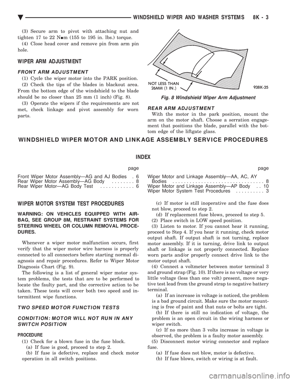
(2) Check the tips of the blades in blackout area.
From the bottom edge of the windshield to the blade
should be no closer than 25 mm (1 inch) (Fig. 8). (3) Operate the wipers if the requirements are not
met, check linkage and pivot assembly for worn
parts.
REAR ARM ADJUSTMENT
With the motor in the park position, mount the
arm on the motor shaft. Choose a serration engage-
ment that positions the blade, parallel with the bot-
tom edge of the liftgate glass.
WINDSHIELD WIPER MOTOR AND LINKAGE ASSEMBLY SERVICE PROCEDURES
INDEX
page page
Front Wiper Motor AssemblyÐAG and AJ Bodies . 6
Rear Wiper Motor AssemblyÐAG Body ........ 8
Rear Wiper MotorÐAG Body Test ............ 6 Wiper Motor and Linkage AssemblyÐAA, AC, AY
Bodies ................................ 8
Wiper Motor and Linkage AssemblyÐAP Body . . 10
Wiper Motor System Test Procedures .......... 3
WIPER MOTOR SYSTEM TEST PROCEDURES
WARNING: ON VEHICLES EQUIPPED WITH AIR-
BAG, SEE GROUP 8M, RESTRAINT SYSTEMS FOR
STEERING WHEEL OR COLUMN REMOVAL PROCE-
DURES.
Whenever a wiper motor malfunction occurs, first
verify that the wiper motor wire harness is properly
connected to all connectors before starting normal di-
agnosis and repair procedures. Refer to Wiper Motor
Diagnosis Chart (Fig. 9). The following is a list of general wiper motor sys-
tem problems, the tests that are to be performed to
locate the faulty part, and the corrective action to be
taken. These tests will cover both two speed and in-
termittent wipe functions.
TWO SPEED MOTOR FUNCTION TESTS
CONDITION: MOTOR WILL NOT RUN IN ANY SWITCH POSITION
PROCEDURE
(1) Check for a blown fuse in the fuse block. (a) If fuse is good, proceed to step 2.
(b) If fuse is defective, replace and check motor
operation in all switch positions. (c) If motor is still inoperative and the fuse does
not blow, proceed to step 2. (d) If replacement fuse blows, proceed to step 5.
(2) Place switch in LOW speed position.
(3) Listen to motor. If you cannot hear it running,
proceed to Step 4. If you hear it running, check motor
output shaft. If output shaft is not turning, replace
motor assembly. If it is turning, drive link to output
shaft or linkage is not properly connected. Replace
worn parts and/or properly connect drive link to the
motor output shaft. (4) Connect a voltmeter between motor terminal 3
and ground strap (Fig. 10). If there is no voltage or very
little voltage (less than one volt) present, move nega-
tive test lead from the ground strap to negative battery
terminal. (a) If an increase in voltage is noticed, the problem
is a bad ground circuit. Make sure the motor mount-
ing is free of paint and that nuts or bolts are tight. (b) If there is still no indication of voltage, the
problem is an open circuit in the wiring harness or
wiper switch. (c) If no more than 3 volts increase in voltage is
observed, the problem is a faulty motor assembly.
(5) Disconnect motor wiring connector and replace
fuse. (a) If fuse does not blow, motor is defective.
(b) If fuse blows, switch or wiring is at fault.
Fig. 8 Windshield Wiper Arm Adjustment
Ä WINDSHIELD WIPER AND WASHER SYSTEMS 8K - 3
Page 1580 of 2438
CAUTION: Make sure clutch cable has been discon-
nected. (20) Remove front engine mount screw and nut.
(21) Remove manual transmission damper.
(22) Remove left insulator through bolt from inside
wheelhouse or insulator bracket to transmission
screws. (23) Remove engine from vehicle.
INSTALLATION
(1) Install hoist to the engine and lower engine
into the engine compartment. SEE: ENGINE MOUNT RUBBER INSULATORS,
THIS GROUP. (2) Align engine mounts and install but do not
tighten until all mounting bolts have been installed.
(3) Install transmission case to cylinder block
mounting screws. Tighten to 95 N Im (70 ft. lbs.)
torque. (4) Remove engine hoist and transmission holding
fixture. (5) Install ground strap.
(6) Install right inner splash shield.
(7) Connect starter. See Electrical Group 8 for in-
stallation. (8) Connect exhaust system. See Exhaust Systems
Group 11 for installation. (9) Manual Transmission: Install transmission
case lower cover. Automatic Transmission: Remove C clamp from
torque converter housing. Align flexplate to torque
converter and install mounting screws. Tighten to 75
N Im (55 ft. lbs.) torque.
(10) Manual Transmission: Connect clutch cable.
See Clutch Group 6. (11) Install power steering pump. Refer to Cooling
System Group 7, Accessory Drive Section for belt
tension adjustment. (12) Connect fuel line, heater hose, and accelerator
cable. (13) Connect all electrical connections and har-
nesses at throttle body and engine. (14) Install oil filter. Fill engine crankcase with
proper oil to correct level. (15) Install air conditioning compressor (if
equipped). See Heater and Air Conditioning, Group
24 for installation. (16) Install air cleaner and hoses.
(17) Install radiator and shroud assembly . Install
radiator hoses. Fill cooling system. See Cooling Sys-
tem Group 7 for filling procedure. (18) Install hood.
(19) Connect battery.
(20) Start engine and run until operating temper-
ature is reached. (21) Adjust transmission linkage, if necessary.
SOLID MOUNT COMPRESSOR BRACKET SERVICE
When service procedures require solid mount
bracket removal and installation for example: cylin-
der head removal, etc., it is important that bracket
fasteners numbered 1 through 7 (Fig. 4) be removed
and installed in sequence, as instructed in Remove
and Install.
ACCESSORIES REMOVAL
(1) Remove (and install/adjust) belts,see Accessory
Drive Belts in Cooling System,Group 7. (2) Remove air conditioning compressor (in vehicle
with lines and set aside) (Fig. 6). (3) Remove generator pivot bolt and remove gener-
ator (in vehicle: turn wiring side up and disconnect,
then rotate generator, pulley end towards engine and
remove). (4) Remove air conditioner compressor belt idler.
SOLID MOUNT BRACKETÐREMOVAL (FIG. 4)
(1) Remove right engine mount yoke screw (see
Engine Remove Fig. 3) securing engine mount sup-
port strut to engine mount bracket. (2) Remove five side mounting bolts #1, #4 , #5,
#6, and #7 (Fig. 4). (3) Remove front mounting nut, #2, and remove
front bolt #3*. (4) Remove front mounting bolt and strut, rotate
solid mount bracket away from engine and slide
bracket on stud until #2 nut mounting stud until
free. Remove spacer from stud.
SOLID MOUNT BRACKETÐINSTALLATION
(1) Put spacer onto stud, then install bracket on
front (#2 nut) mounting stud and slide bracket over
timing belt cover into position. (2) Loosen assembly bracket to engine fasteners
(numbered #1 through #7 in Fig. 6). (3)
CAUTION: Fasteners MUST BE TIGHTENED IN SE-
QUENCE and to specified torque as follows :
² First Bolt #1 to 3.3 N Im (30 in. lbs.)
² Second Nut #2 and Bolt #3 to 54 N Im (40 ft. lbs.).
² Third Bolts #1 (second tightening) #4 and #5 to
54 N Im (40 ft. lbs.).
² Fourth Bolts #6 and #7 to 54 N Im (40 ft. lbs.).
(4) Install generator and compressor. Tighten com-
pressor mounting bracket bolts to 54 N Im (40 ft.
lbs.).
SOLID MOUNT COMPRESSOR BRACKET SERVICEÐTURBO III ENGINE
REMOVAL
(1) Disconnect negative battery cable
9 - 14 2.2/2.5L ENGINE Ä
Page 1598 of 2438
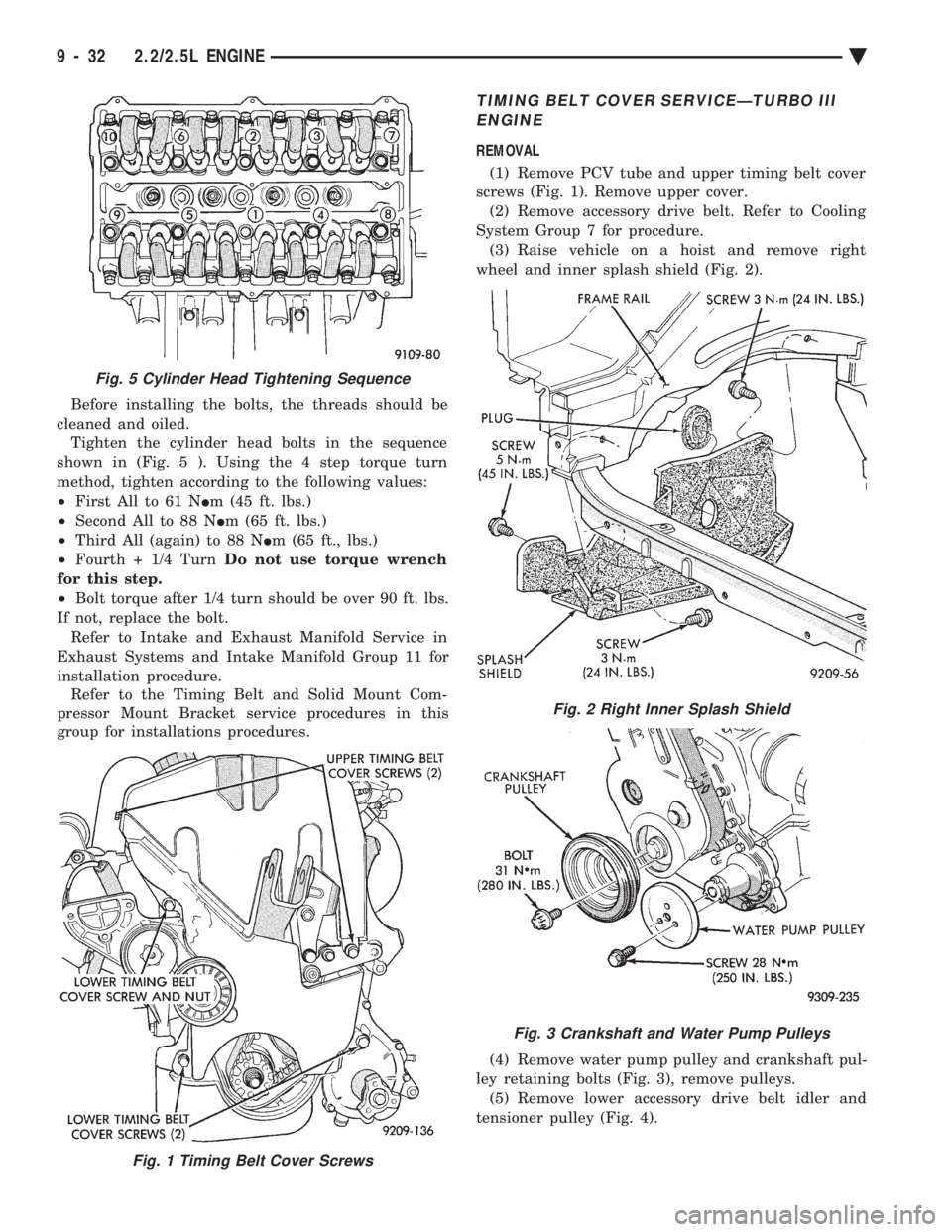
Before installing the bolts, the threads should be
cleaned and oiled. Tighten the cylinder head bolts in the sequence
shown in (Fig. 5 ). Using the 4 step torque turn
method, tighten according to the following values:
² First All to 61 N Im (45 ft. lbs.)
² Second All to 88 N Im (65 ft. lbs.)
² Third All (again) to 88 N Im (65 ft., lbs.)
² Fourth + 1/4 Turn Do not use torque wrench
for this step.
² Bolt torque after 1/4 turn should be over 90 ft. lbs.
If not, replace the bolt. Refer to Intake and Exhaust Manifold Service in
Exhaust Systems and Intake Manifold Group 11 for
installation procedure. Refer to the Timing Belt and Solid Mount Com-
pressor Mount Bracket service procedures in this
group for installations procedures.
TIMING BELT COVER SERVICEÐTURBO III
ENGINE
REMOVAL
(1) Remove PCV tube and upper timing belt cover
screws (Fig. 1). Remove upper cover. (2) Remove accessory drive belt. Refer to Cooling
System Group 7 for procedure. (3) Raise vehicle on a hoist and remove right
wheel and inner splash shield (Fig. 2).
(4) Remove water pump pulley and crankshaft pul-
ley retaining bolts (Fig. 3), remove pulleys. (5) Remove lower accessory drive belt idler and
tensioner pulley (Fig. 4).
Fig. 1 Timing Belt Cover Screws
Fig. 5 Cylinder Head Tightening Sequence
Fig. 2 Right Inner Splash Shield
Fig. 3 Crankshaft and Water Pump Pulleys
9 - 32 2.2/2.5L ENGINE Ä
Page 1599 of 2438
CAUTION: Do not use a impact wrench to remove
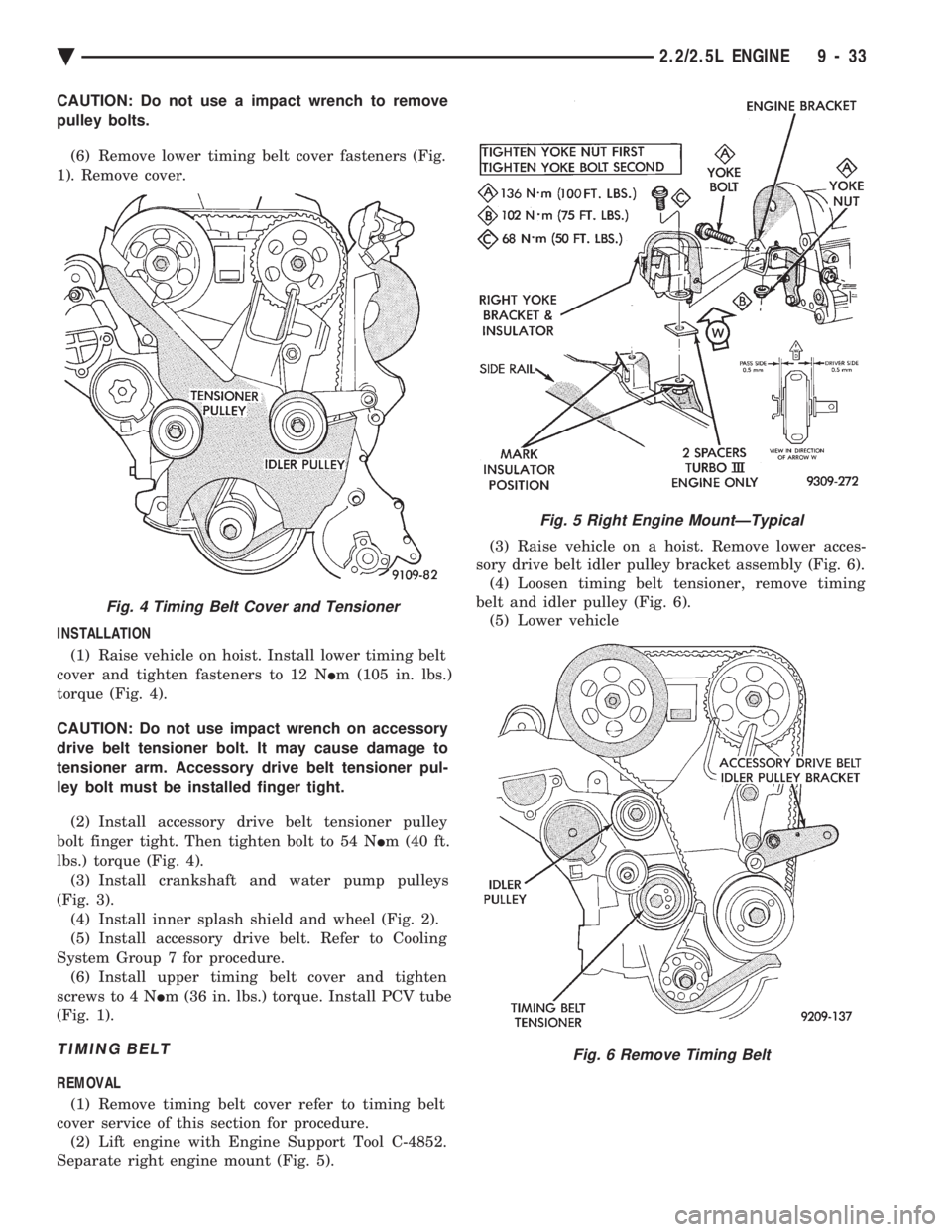
pulley bolts. (6) Remove lower timing belt cover fasteners (Fig.
1). Remove cover.
INSTALLATION (1) Raise vehicle on hoist. Install lower timing belt
cover and tighten fasteners to 12 N Im (105 in. lbs.)
torque (Fig. 4).
CAUTION: Do not use impact wrench on accessory
drive belt tensioner bolt. It may cause damage to
tensioner arm. Accessory drive belt tensioner pul-
ley bolt must be installed finger tight. (2) Install accessory drive belt tensioner pulley
bolt finger tight. Then tighten bolt to 54 N Im (40 ft.
lbs.) torque (Fig. 4). (3) Install crankshaft and water pump pulleys
(Fig. 3). (4) Install inner splash shield and wheel (Fig. 2).
(5) Install accessory drive belt. Refer to Cooling
System Group 7 for procedure. (6) Install upper timing belt cover and tighten
screws to 4 N Im (36 in. lbs.) torque. Install PCV tube
(Fig. 1).
TIMING BELT
REMOVAL
(1) Remove timing belt cover refer to timing belt
cover service of this section for procedure. (2) Lift engine with Engine Support Tool C-4852.
Separate right engine mount (Fig. 5). (3) Raise vehicle on a hoist. Remove lower acces-
sory drive belt idler pulley bracket assembly (Fig. 6). (4) Loosen timing belt tensioner, remove timing
belt and idler pulley (Fig. 6). (5) Lower vehicle
Fig. 4 Timing Belt Cover and Tensioner
Fig. 5 Right Engine MountÐTypical
Fig. 6 Remove Timing Belt
Ä 2.2/2.5L ENGINE 9 - 33
Page 1635 of 2438
LEFT SIDE MOUNT
(1) Raise vehicle on hoist and remove left front
wheel. (2) Remove inter splash shield.
(3) Support the transmission with a transmission
jack. (4) Remove the insulator thru bolt from the mount.
(5) Remove the transmission mount fasteners and
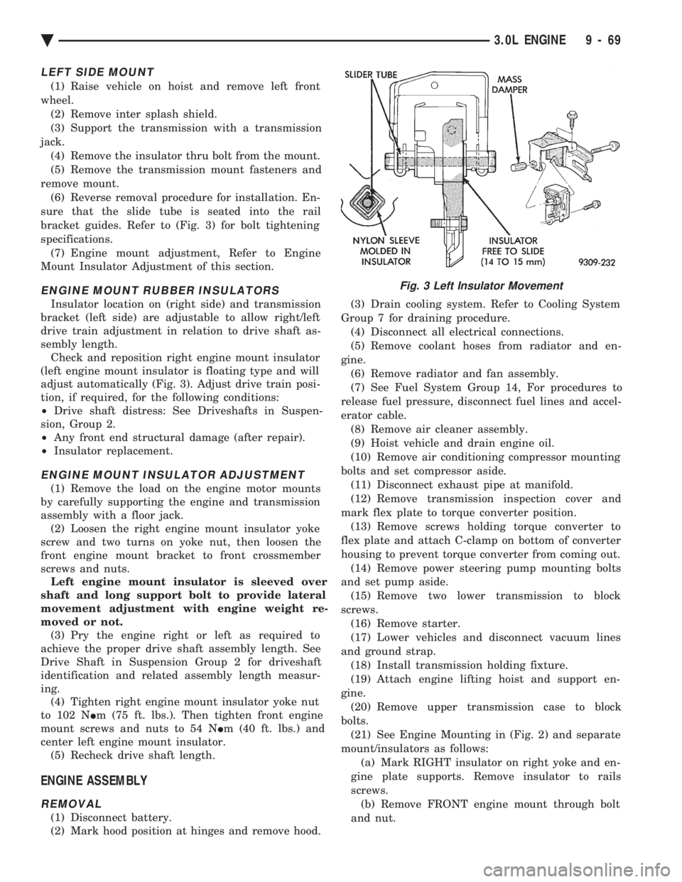
remove mount. (6) Reverse removal procedure for installation. En-
sure that the slide tube is seated into the rail
bracket guides. Refer to (Fig. 3) for bolt tightening
specifications. (7) Engine mount adjustment, Refer to Engine
Mount Insulator Adjustment of this section.
ENGINE MOUNT RUBBER INSULATORS
Insulator location on (right side) and transmission
bracket (left side) are adjustable to allow right/left
drive train adjustment in relation to drive shaft as-
sembly length. Check and reposition right engine mount insulator
(left engine mount insulator is floating type and will
adjust automatically (Fig. 3). Adjust drive train posi-
tion, if required, for the following conditions:
² Drive shaft distress: See Driveshafts in Suspen-
sion, Group 2.
² Any front end structural damage (after repair).
² Insulator replacement.
ENGINE MOUNT INSULATOR ADJUSTMENT
(1) Remove the load on the engine motor mounts
by carefully supporting the engine and transmission
assembly with a floor jack. (2) Loosen the right engine mount insulator yoke
screw and two turns on yoke nut, then loosen the
front engine mount bracket to front crossmember
screws and nuts. Left engine mount insulator is sleeved over
shaft and long support bolt to provide lateral
movement adjustment with engine weight re-
moved or not. (3) Pry the engine right or left as required to
achieve the proper drive shaft assembly length. See
Drive Shaft in Suspension Group 2 for driveshaft
identification and related assembly length measur-
ing. (4) Tighten right engine mount insulator yoke nut
to 102 N Im (75 ft. lbs.). Then tighten front engine
mount screws and nuts to 54 N Im (40 ft. lbs.) and
center left engine mount insulator. (5) Recheck drive shaft length.
ENGINE ASSEMBLY
REMOVAL
(1) Disconnect battery.
(2) Mark hood position at hinges and remove hood. (3) Drain cooling system. Refer to Cooling System
Group 7 for draining procedure. (4) Disconnect all electrical connections.
(5) Remove coolant hoses from radiator and en-
gine. (6) Remove radiator and fan assembly.
(7) See Fuel System Group 14, For procedures to
release fuel pressure, disconnect fuel lines and accel-
erator cable. (8) Remove air cleaner assembly.
(9) Hoist vehicle and drain engine oil.
(10) Remove air conditioning compressor mounting
bolts and set compressor aside. (11) Disconnect exhaust pipe at manifold.
(12) Remove transmission inspection cover and
mark flex plate to torque converter position. (13) Remove screws holding torque converter to
flex plate and attach C-clamp on bottom of converter
housing to prevent torque converter from coming out. (14) Remove power steering pump mounting bolts
and set pump aside. (15) Remove two lower transmission to block
screws. (16) Remove starter.
(17) Lower vehicles and disconnect vacuum lines
and ground strap. (18) Install transmission holding fixture.
(19) Attach engine lifting hoist and support en-
gine. (20) Remove upper transmission case to block
bolts. (21) See Engine Mounting in (Fig. 2) and separate
mount/insulators as follows: (a) Mark RIGHT insulator on right yoke and en-
gine plate supports. Remove insulator to rails
screws. (b) Remove FRONT engine mount through bolt
and nut.
Fig. 3 Left Insulator Movement
Ä 3.0L ENGINE 9 - 69
Page 1636 of 2438
(c) Remove LEFT insulator through bolt from in-
side wheelhouse or insulator bracket to transmis-
sion screws.
(22) Remove engine.
INSTALLATION
(1) Attach hoist and lower engine into engine com-
partment. (2) Align engine mounts and install but do not
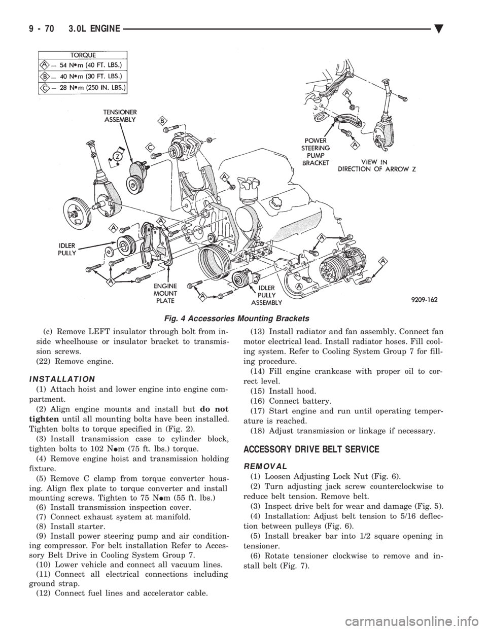
tighten until all mounting bolts have been installed.
Tighten bolts to torque specified in (Fig. 2). (3) Install transmission case to cylinder block,
tighten bolts to 102 N Im (75 ft. lbs.) torque.
(4) Remove engine hoist and transmission holding
fixture. (5) Remove C clamp from torque converter hous-
ing. Align flex plate to torque converter and install
mounting screws. Tighten to 75 N Im (55 ft. lbs.)
(6) Install transmission inspection cover.
(7) Connect exhaust system at manifold.
(8) Install starter.
(9) Install power steering pump and air condition-
ing compressor. For belt installation Refer to Acces-
sory Belt Drive in Cooling System Group 7. (10) Lower vehicle and connect all vacuum lines.
(11) Connect all electrical connections including
ground strap. (12) Connect fuel lines and accelerator cable. (13) Install radiator and fan assembly. Connect fan
motor electrical lead. Install radiator hoses. Fill cool-
ing system. Refer to Cooling System Group 7 for fill-
ing procedure. (14) Fill engine crankcase with proper oil to cor-
rect level. (15) Install hood.
(16) Connect battery.
(17) Start engine and run until operating temper-
ature is reached. (18) Adjust transmission or linkage if necessary.
ACCESSORY DRIVE BELT SERVICE
REMOVAL
(1) Loosen Adjusting Lock Nut (Fig. 6).
(2) Turn adjusting jack screw counterclockwise to
reduce belt tension. Remove belt. (3) Inspect drive belt for wear and damage (Fig. 5).
(4) Installation: Adjust belt tension to 5/16 deflec-
tion between pulleys (Fig. 6). (5) Install breaker bar into 1/2 square opening in
tensioner. (6) Rotate tensioner clockwise to remove and in-
stall belt (Fig. 7).
Fig. 4 Accessories Mounting Brackets
9 - 70 3.0L ENGINE Ä
Page 1667 of 2438
(2) Loosen the right engine mount insulator yoke
screw and 2 turns on yoke nut, then loosen the front
engine mount bracket to front crossmember screws and
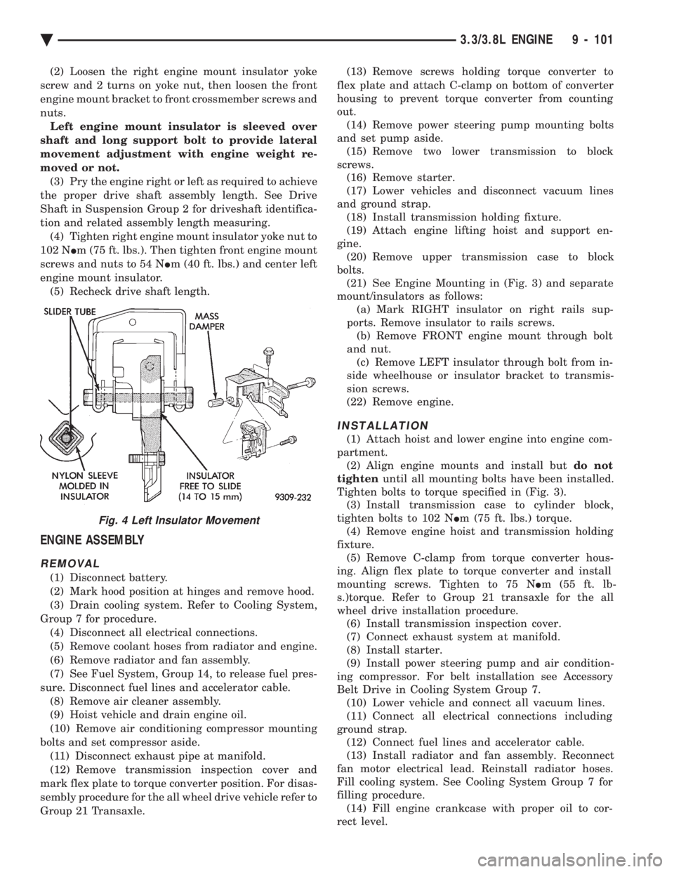
nuts. Left engine mount insulator is sleeved over
shaft and long support bolt to provide lateral
movement adjustment with engine weight re-
moved or not. (3) Pry the engine right or left as required to achieve
the proper drive shaft assembly length. See Drive
Shaft in Suspension Group 2 for driveshaft identifica-
tion and related assembly length measuring. (4) Tighten right engine mount insulator yoke nut to
102 N Im (75 ft. lbs.). Then tighten front engine mount
screws and nuts to 54 N Im (40 ft. lbs.) and center left
engine mount insulator. (5) Recheck drive shaft length.
ENGINE ASSEMBLY
REMOVAL
(1) Disconnect battery.
(2) Mark hood position at hinges and remove hood.
(3) Drain cooling system. Refer to Cooling System,
Group 7 for procedure. (4) Disconnect all electrical connections.
(5) Remove coolant hoses from radiator and engine.
(6) Remove radiator and fan assembly.
(7) See Fuel System, Group 14, to release fuel pres-
sure. Disconnect fuel lines and accelerator cable. (8) Remove air cleaner assembly.
(9) Hoist vehicle and drain engine oil.
(10) Remove air conditioning compressor mounting
bolts and set compressor aside. (11) Disconnect exhaust pipe at manifold.
(12) Remove transmission inspection cover and
mark flex plate to torque converter position. For disas-
sembly procedure for the all wheel drive vehicle refer to
Group 21 Transaxle. (13) Remove screws holding torque converter to
flex plate and attach C-clamp on bottom of converter
housing to prevent torque converter from counting
out. (14) Remove power steering pump mounting bolts
and set pump aside. (15) Remove two lower transmission to block
screws. (16) Remove starter.
(17) Lower vehicles and disconnect vacuum lines
and ground strap. (18) Install transmission holding fixture.
(19) Attach engine lifting hoist and support en-
gine. (20) Remove upper transmission case to block
bolts. (21) See Engine Mounting in (Fig. 3) and separate
mount/insulators as follows: (a) Mark RIGHT insulator on right rails sup-
ports. Remove insulator to rails screws. (b) Remove FRONT engine mount through bolt
and nut. (c) Remove LEFT insulator through bolt from in-
side wheelhouse or insulator bracket to transmis-
sion screws.
(22) Remove engine.
INSTALLATION
(1) Attach hoist and lower engine into engine com-
partment. (2) Align engine mounts and install but do not
tighten until all mounting bolts have been installed.
Tighten bolts to torque specified in (Fig. 3). (3) Install transmission case to cylinder block,
tighten bolts to 102 N Im (75 ft. lbs.) torque.
(4) Remove engine hoist and transmission holding
fixture. (5) Remove C-clamp from torque converter hous-
ing. Align flex plate to torque converter and install
mounting screws. Tighten to 75 N Im (55 ft. lb-
s.)torque. Refer to Group 21 transaxle for the all
wheel drive installation procedure. (6) Install transmission inspection cover.
(7) Connect exhaust system at manifold.
(8) Install starter.
(9) Install power steering pump and air condition-
ing compressor. For belt installation see Accessory
Belt Drive in Cooling System Group 7. (10) Lower vehicle and connect all vacuum lines.
(11) Connect all electrical connections including
ground strap. (12) Connect fuel lines and accelerator cable.
(13) Install radiator and fan assembly. Reconnect
fan motor electrical lead. Reinstall radiator hoses.
Fill cooling system. See Cooling System Group 7 for
filling procedure. (14) Fill engine crankcase with proper oil to cor-
rect level.
Fig. 4 Left Insulator Movement
Ä 3.3/3.8L ENGINE 9 - 101