1993 CHEVROLET PLYMOUTH ACCLAIM brake rotor
[x] Cancel search: brake rotorPage 31 of 2438
COMPONENT AND SYSTEM INDEX
Name Group-page Name Group-page
BODY ................................... 23-1
AA-VEHICLE BODY COMPONENT SERVICE .......23-11
AC-VEHICLE BODY COMPONENT SERVICE .......23-37
AG-VEHICLE BODY COMPONENT SERVICE .......23-52
AJ/27-VEHICLE CONVERTIBLE BODY COMPONENT SERVICE ............................ 23-86
AJ-VEHICLE BODY COMPONENT SERVICE .......23-71
AP-VEHICLE BODY COMPONENT SERVICE .......23-97
AY-VEHICLE BODY COMPONENT SERVICE .......23-133
BODY DIAGNOSTIC PROCEDURES .............23-2
GENERAL SERVICE INFORMATION .............23-1
PAINT ................................. 23-4
POWER SUNROOF ........................ 23-6
WINDSHIELD ............................ 23-9
BRAKES ..................................5-1
ANTI-LOCK BRAKE SYSTEMÐBENDIX ANTI-LOCK 10 AC/Y BODY ......................... 5-72
ANTI-LOCK BRAKE SYSTEMÐBENDIX ANTI-LOCK 6 AA,AG,AJ,AP BODY .................... 5-113
BRAKE DISC (ROTOR) ...................... 5-53
BRAKE SUPPORT ASSEMBLY .................5-25
FRONT DISC BRAKES ...................... 5-31
GENERAL INFORMATION .....................5-1
HYDRAULIC SYSTEM CONTROL VALVES .........5-26
KELSEY HAYES DOUBLE PIN FAMILY CALIPER .....5-35
KELSEY HAYES DOUBLE PIN NON-FAMILY CALIPER ............................. 5-38
MASTER CYLINDER ....................... 5-66
PARKING BRAKES ........................ 5-57
POWER BRAKES ......................... 5-68
REAR DISC BRAKES ....................... 5-45
REAR WHEEL DRUM BRAKES ................5-18
SERVICE ADJUSTMENTS .....................5-4
WHEEL BEARINGS ........................ 5-70
WHEEL CYLINDERS ....................... 5-23
COOLING SYSTEM ...........................7-1
ACCESSORY DRIVE BELTS ................... 7-24
ENGINE BLOCK HEATER .................... 7-28
GENERAL INFORMATION .....................7-1
SERVICE PROCEDURES ..................... 7-10
SPECIFICATIONS ......................... 7-29
ENGINE ..................................9-1
2.2/2.5L ENGINES .........................9-8
3.0L ENGINE ............................ 9-66
3.3/3.8L ENGINE ......................... 9-98
STANDARD SERVICE PROCEDURES .............9-1
EXHAUST SYSTEM AND INTAKE MANIFOLD .........11-1
GENERAL INFORMATION .................... 11-1
SERVICE PROCEDURES ..................... 11-4
TORQUE SPECIFICATION ................... 11-25
FRAME AND BUMPERS ....................... 13-1
BUMPER AND FASCIA ...................... 13-1
FRAME ................................ 13-9
HEATING AND AIR CONDITIONING ...............24-1
AUTOMATIC TEMPERATURE CONTROL (ATC) .....24-66 COMPONENT SERVICE PROCEDURES
..........24-47
FIXED DISPLACEMENT COMPRESSORÐMODEL 10PA17............................. 24-24
FIXED DISPLACEMENT COMPRESSORÐMODEL SD709P ............................. 24-38
FIXED DISPLACEMENT COMPRESSORÐMODEL TR105 .............................. 24-32
GENERAL INFORMATION .................... 24-1
HEATER AND A/C PERFORMANCE TESTS .........24-6
REFRIGERANT SERVICE PROCEDURES ..........24-8
VACUUM CONTROL SYSTEM DIAGNOSIS .........24-4
VARIABLE DISPLACEMENT COMPRESSORÐMODEL 6C17 ............................... 24-13
INTRODUCTION .......................... Intro.-1
LUBRICATION AND MAINTENANCE ................0-1
CHASSIS AND BODY ....................... 0-19
DRIVETRAIN ............................ 0-16
ENGINE ................................0-8
GENERAL INFORMATION .....................0-1
MANUAL TRANSAXLE CLUTCH ...................6-1
STEERING ................................ 19-1
ACUSTAR STANDARD AND TILT STEERING COLUMN ............................ 19-28
AUTOMATIC TRANSMISSION SHIFTER/IGNITION INTERLOCK .......................... 19-36
GENERAL INFORMATION .................... 19-1
POWER STEERING GEAR ................... 19-25
POWER STEERING PUMPS ..................19-1
SPECIFICATIONS AND TIGHTENING REFERENCE . . . 19-42
SUSPENSION AND DRIVESHAFTS .................2-1
AUTOMATIC AIR LOAD LEVELING SYSTEM ........2-59
AUTOMATIC AIR SUSPENSION ................2-73
DRIVESHAFTS ........................... 2-25
FRONT SUSPENSION .......................2-2
FRONT SUSPENSION SERVICE PROCEDURES .......2-5
GENERAL INFORMATION .....................2-1
REAR (STUB) AXLE ALIGNMENT ALL MODELS .....2-89
REAR SUSPENSION ....................... 2-50
SPECIFICATIONS ......................... 2-91
TRANSAXLE .............................. 21-85
41TE FOUR SPEED AUTOMATIC TRANSAXLE ......21-85
41TE FOUR SPEED TRANSAXLE HYDRAULIC SCHEMATICS ........................ 21-170
41TE ON-BOARD DIAGNOSTICS .............21-145
A-523, A-543, and A-568 MANUAL TRANSAXLE ....21-1
SPECIFICATIONS ........................ 21-183
THREE SPEED TORQUEFLITE AUTOMATIC TRANSAXLE .......................... 21-35
THREE SPEED TRANSAXLE HYDRAULIC SCHEMATICS ........................ 21-162
WHEELSÐTIRES ........................... 22-1
SPECIFICATIONS ......................... 22-8
TIRE SERVICE PROCEDURES .................22-1
WHEELS SERVICE PROCEDURES ..............22-6
Page 43 of 2438
TOWING RECOMMENDATIONS
RECOMMENDED TOWING EQUIPMENT
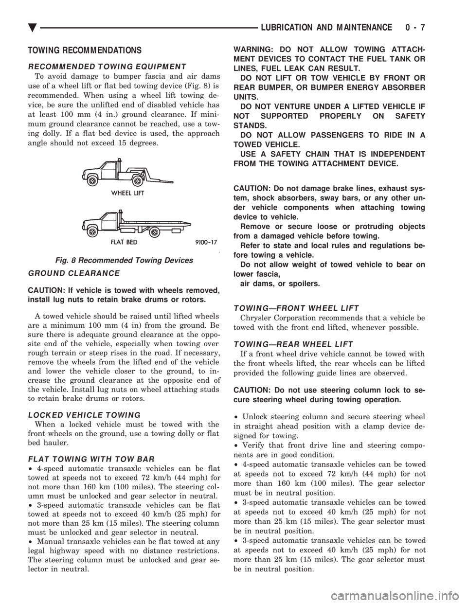
To avoid damage to bumper fascia and air dams
use of a wheel lift or flat bed towing device (Fig. 8) is
recommended. When using a wheel lift towing de-
vice, be sure the unlifted end of disabled vehicle has
at least 100 mm (4 in.) ground clearance. If mini-
mum ground clearance cannot be reached, use a tow-
ing dolly. If a flat bed device is used, the approach
angle should not exceed 15 degrees.
GROUND CLEARANCE
CAUTION: If vehicle is towed with wheels removed,
install lug nuts to retain brake drums or rotors.
A towed vehicle should be raised until lifted wheels
are a minimum 100 mm (4 in) from the ground. Be
sure there is adequate ground clearance at the oppo-
site end of the vehicle, especially when towing over
rough terrain or steep rises in the road. If necessary,
remove the wheels from the lifted end of the vehicle
and lower the vehicle closer to the ground, to in-
crease the ground clearance at the opposite end of
the vehicle. Install lug nuts on wheel attaching studs
to retain brake drums or rotors.
LOCKED VEHICLE TOWING
When a locked vehicle must be towed with the
front wheels on the ground, use a towing dolly or flat
bed hauler.
FLAT TOWING WITH TOW BAR
² 4-speed automatic transaxle vehicles can be flat
towed at speeds not to exceed 72 km/h (44 mph) for
not more than 160 km (100 miles). The steering col-
umn must be unlocked and gear selector in neutral.
² 3-speed automatic transaxle vehicles can be flat
towed at speeds not to exceed 40 km/h (25 mph) for
not more than 25 km (15 miles). The steering column
must be unlocked and gear selector in neutral.
² Manual transaxle vehicles can be flat towed at any
legal highway speed with no distance restrictions.
The steering column must be unlocked and gear se-
lector in neutral. WARNING: DO NOT ALLOW TOWING ATTACH-
MENT DEVICES TO CONTACT THE FUEL TANK OR
LINES, FUEL LEAK CAN RESULT. DO NOT LIFT OR TOW VEHICLE BY FRONT OR
REAR BUMPER, OR BUMPER ENERGY ABSORBER
UNITS. DO NOT VENTURE UNDER A LIFTED VEHICLE IF
NOT SUPPORTED PROPERLY ON SAFETY
STANDS. DO NOT ALLOW PASSENGERS TO RIDE IN A
TOWED VEHICLE. USE A SAFETY CHAIN THAT IS INDEPENDENT
FROM THE TOWING ATTACHMENT DEVICE.
CAUTION: Do not damage brake lines, exhaust sys-
tem, shock absorbers, sway bars, or any other un-
der vehicle components when attaching towing
device to vehicle. Remove or secure loose or protruding objects
from a damaged vehicle before towing. Refer to state and local rules and regulations be-
fore towing a vehicle. Do not allow weight of towed vehicle to bear on
lower fascia, air dams, or spoilers.
TOWINGÐFRONT WHEEL LIFT
Chrysler Corporation recommends that a vehicle be
towed with the front end lifted, whenever possible.
TOWINGÐREAR WHEEL LIFT
If a front wheel drive vehicle cannot be towed with
the front wheels lifted, the rear wheels can be lifted
provided the following guide lines are observed.
CAUTION: Do not use steering column lock to se-
cure steering wheel during towing operation.
² Unlock steering column and secure steering wheel
in straight ahead position with a clamp device de-
signed for towing.
² Verify that front drive line and steering compo-
nents are in good condition.
² 4-speed automatic transaxle vehicles can be towed
at speeds not to exceed 72 km/h (44 mph) for not
more than 160 km (100 miles). The gear selector
must be in neutral position.
² 3-speed automatic transaxle vehicles can be towed
at speeds not to exceed 40 km/h (25 mph) for not
more than 25 km (15 miles). The gear selector must
be in neutral position.
² 3-speed automatic transaxle vehicles can be towed
at speeds not to exceed 40 km/h (25 mph) for not
more than 25 km (15 miles). The gear selector must
be in neutral position.
Fig. 8 Recommended Towing Devices
Ä LUBRICATION AND MAINTENANCE 0 - 7
Page 151 of 2438

BRAKES
CONTENTS
page page
ANTI-LOCK BRAKE SYSTEMÐBENDIX ANTI-LOCK 10 AC/Y BODY ............. 72
ANTI-LOCK BRAKE SYSTEMÐBENDIX ANTI-LOCK 6 AA,AG,AJ,AP BODY ....... 113
BRAKE DISC (ROTOR) ................... 53
BRAKE SUPPORT ASSEMBLY ............. 25
FRONT DISC BRAKES ................... 31
GENERAL INFORMATION .................. 1
HYDRAULIC SYSTEM CONTROL VALVES . . . 26
KELSEY HAYES DOUBLE PIN FAMILY CALIPER ............................ 35 KELSEY HAYES DOUBLE PIN NON-FAMILY
CALIPER ............................ 38
MASTER CYLINDER ..................... 66
PARKING BRAKES ...................... 57
POWER BRAKES ....................... 68
REAR DISC BRAKES .................... 45
REAR WHEEL DRUM BRAKES ............ 18
SERVICE ADJUSTMENTS .................. 4
WHEEL BEARINGS ...................... 70
WHEEL CYLINDERS ..................... 23
GENERAL INFORMATION
Throughout this group, references may be made to
a particular vehicle by letter or number designation.
A chart showing the break down of these designa-
tions is included in the Introduction Section at the
front of this service manual. Standard brake equipment consists of:
² Double pin floating caliper disc front brakes.
² Rear automatic adjusting drum brakes.
² Differential valve with a brake warning switch.
² Master cylinder.
² Vacuum power booster.
² Double pin floating caliper rear disc brakes are
available on some models. The Bendix Anti-Lock 10 braking system, uses the
standard power brake system caliper assemblies,
braking discs, pedal assembly, brake lines and hoses.
The unique parts of the Bendix Anti-Lock 10 braking
system consists of the following components. Propor-
tioning valves, wheel speed sensors, tone wheels,
electronic control unit, modulator assembly and hy-
draulic assembly. These components replace the con-
ventional master cylinder and power booster. The
components will be described in detail in the Bendix
Anti-Lock 10 brake section in this group of the ser-
vice manual. The Bendix Anti-Lock 6 braking system, uses the
following standard brake system components. Master
cylinder, power booster, caliper assemblies, braking
discs, pedal assembly, brake lines and hoses. The
unique parts of the Bendix Anti-Lock 6 braking sys-
tem consists of the following components. Modulator
assembly, unique proportioning valves, wheel speed
sensors, tone wheels, and electronic control unit.
These components will be described in detail in the
Bendix Anti-Lock 6 brake section in this group of the
service manual. The front disc brake shoes have semi-metallic lin-
ings. The hydraulic brake system (Fig .123and4)is
diagonally split on both the Non-ABS and ABS brak-
ing system. With the left front and right rear brakes
on one hydraulic system and the right front and left
rear on the other. The Non-ABS and ABS brake system may use dif-
ferent types of brake line fittings and tubing flares.
The Non-ABS brake system uses double wall tubing
flares and fittings at all tubing joint locations. Some
ABS brake systems use both ISO style tubing flares
and double wall tubing flares and corresponding fit-
tings at different joint locations. See (Figs . 2 3 and 4)
for specific joint locations and type of tubing flare. The front disc brakes consist of two different types
of caliper assemblies. A double pin Kelsey-Hayes cal-
iper (family caliper) with a bolt-on adapter attached
to the steering knuckle. Or a double pin Kelsey-
Hayes caliper (non-family caliper) which mounts di-
rectly to rails on the steering knuckle. The non-
family caliper is only used on the AY Body
(Imperials).
CAUTION: Caliper pistons, boots and seals for the
different caliper assemblies used on the front and
rear disc brake assemblies are not interchangeable.
Misusage could result in a complete brake system
failure. Be sure that the parts are replaced with the
correct replacement parts, refer to the parts book
for the type and model year of the vehicle being
worked on.
The master cylinder is anodized, lightweight alu-
minum, with a bore size of 24.0mm, 21.0mm or 7/8
inch.
Ä BRAKES 5 - 1
Page 181 of 2438
FRONT DISC BRAKES INDEX
page page
General Information ....................... 31
Service Precautions ....................... 34 Shoe and Lining Wear
.................... 33
GENERAL INFORMATION
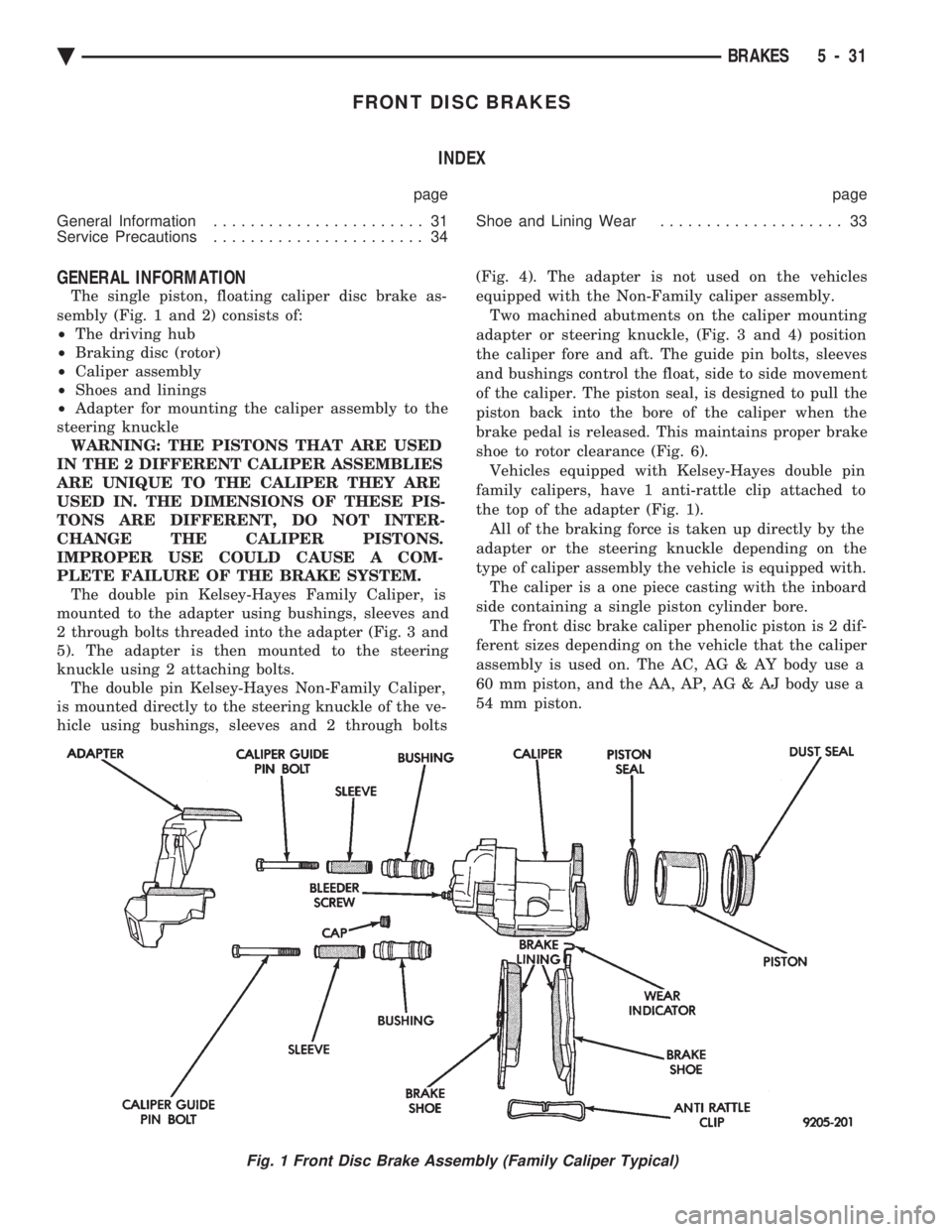
The single piston, floating caliper disc brake as-
sembly (Fig. 1 and 2) consists of:
² The driving hub
² Braking disc (rotor)
² Caliper assembly
² Shoes and linings
² Adapter for mounting the caliper assembly to the
steering knuckle WARNING: THE PISTONS THAT ARE USED
IN THE 2 DIFFERENT CALIPER ASSEMBLIES
ARE UNIQUE TO THE CALIPER THEY ARE
USED IN. THE DIMENSIONS OF THESE PIS-
TONS ARE DIFFERENT, DO NOT INTER-
CHANGE THE CALIPER PISTONS.
IMPROPER USE COULD CAUSE A COM-
PLETE FAILURE OF THE BRAKE SYSTEM. The double pin Kelsey-Hayes Family Caliper, is
mounted to the adapter using bushings, sleeves and
2 through bolts threaded into the adapter (Fig. 3 and
5). The adapter is then mounted to the steering
knuckle using 2 attaching bolts. The double pin Kelsey-Hayes Non-Family Caliper,
is mounted directly to the steering knuckle of the ve-
hicle using bushings, sleeves and 2 through bolts (Fig. 4). The adapter is not used on the vehicles
equipped with the Non-Family caliper assembly.
Two machined abutments on the caliper mounting
adapter or steering knuckle, (Fig. 3 and 4) position
the caliper fore and aft. The guide pin bolts, sleeves
and bushings control the float, side to side movement
of the caliper. The piston seal, is designed to pull the
piston back into the bore of the caliper when the
brake pedal is released. This maintains proper brake
shoe to rotor clearance (Fig. 6). Vehicles equipped with Kelsey-Hayes double pin
family calipers, have 1 anti-rattle clip attached to
the top of the adapter (Fig. 1). All of the braking force is taken up directly by the
adapter or the steering knuckle depending on the
type of caliper assembly the vehicle is equipped with. The caliper is a one piece casting with the inboard
side containing a single piston cylinder bore. The front disc brake caliper phenolic piston is 2 dif-
ferent sizes depending on the vehicle that the caliper
assembly is used on. The AC, AG & AY body use a
60 mm piston, and the AA, AP, AG & AJ body use a
54 mm piston.
Fig. 1 Front Disc Brake Assembly (Family Caliper Typical)
Ä BRAKES 5 - 31
Page 185 of 2438

KELSEY HAYES DOUBLE PIN FAMILY CALIPER
BRAKE SHOE SERVICE PROCEDURES
BRAKE SHOE REMOVAL
(1) Raise vehicle on jackstands or centered on a
hoist. See Hoisting Information in the Lubrication
and Maintenance section of this manual. (2) Remove front wheel and tire assemblies.
(3) Remove caliper guide pin bolts (Fig. 1).
(4) After removing caliper guide pin bolts. Lift cal-
iper away from braking disc using a pry bar or
screwdriver (Fig. 2). (5) Remove caliper assembly from braking disc and
adapter by sliding the assembly out and away from
the braking disc and adapter (Fig. 3). (6) Support caliper firmly to prevent weight of cal-
iper from damaging the flexible brake hose (Fig. 4). (7) Remove the outboard brake shoe assembly from
the caliper adapter (Fig. 5). (8) Remove the braking disk (rotor) from the hub
by pulling it straight off the wheel mounting studs
(Fig. 6).
Fig. 1 Removing or Installing Caliper Guide Pin Bolts
Fig. 2 Loosening Family Caliper Assembly FromAdapter And Rotor
Fig. 3 Removing or Installing Caliper Assembly
Ä BRAKES 5 - 35
Page 195 of 2438
REAR DISC BRAKES INDEX
page page
Assembling Rear Disc Brake Caliper .......... 49
Brake Shoe Removal ..................... 46
Cleaning and Inspection ................... 49
Disassembling Rear Caliper Assembly ......... 48 General Information
....................... 45
Lining Wear ............................. 45
Service Precautions ....................... 46
GENERAL INFORMATION
The rear disc brakes are similar to front disc
brakes, however, there are several distinctive fea-
tures that require different service procedures. This
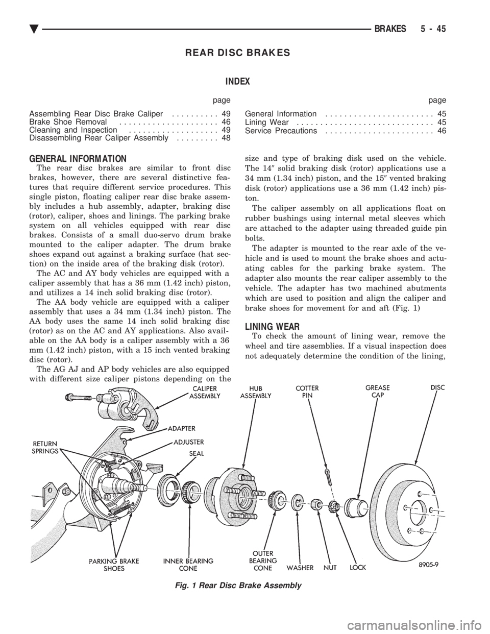
single piston, floating caliper rear disc brake assem-
bly includes a hub assembly, adapter, braking disc
(rotor), caliper, shoes and linings. The parking brake
system on all vehicles equipped with rear disc
brakes. Consists of a small duo-servo drum brake
mounted to the caliper adapter. The drum brake
shoes expand out against a braking surface (hat sec-
tion) on the inside area of the braking disk (rotor). The AC and AY body vehicles are equipped with a
caliper assembly that has a 36 mm (1.42 inch) piston,
and utilizes a 14 inch solid braking disc (rotor). The AA body vehicle are equipped with a caliper
assembly that uses a 34 mm (1.34 inch) piston. The
AA body uses the same 14 inch solid braking disc
(rotor) as on the AC and AY applications. Also avail-
able on the AA body is a caliper assembly with a 36
mm (1.42 inch) piston, with a 15 inch vented braking
disc (rotor). The AG AJ and AP body vehicles are also equipped
with different size caliper pistons depending on the size and type of braking disk used on the vehicle.
The 14 9solid braking disk (rotor) applications use a
34 mm (1.34 inch) piston, and the 15 9vented braking
disk (rotor) applications use a 36 mm (1.42 inch) pis-
ton. The caliper assembly on all applications float on
rubber bushings using internal metal sleeves which
are attached to the adapter using threaded guide pin
bolts. The adapter is mounted to the rear axle of the ve-
hicle and is used to mount the brake shoes and actu-
ating cables for the parking brake system. The
adapter also mounts the rear caliper assembly to the
vehicle. The adapter has two machined abutments
which are used to position and align the caliper and
brake shoes for movement for and aft (Fig. 1)
LINING WEAR
To check the amount of lining wear, remove the
wheel and tire assemblies. If a visual inspection does
not adequately determine the condition of the lining,
Fig. 1 Rear Disc Brake Assembly
Ä BRAKES 5 - 45
Page 197 of 2438
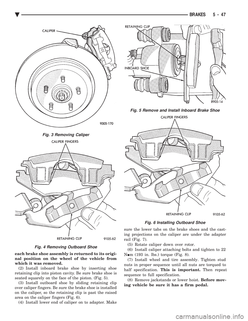
each brake shoe assembly is returned to its origi-
nal position on the wheel of the vehicle from
which it was removed. (2) Install inboard brake shoe by inserting shoe
retaining clip into piston cavity. Be sure brake shoe is
seated squarely on the face of the piston. (Fig. 5). (3) Install outboard shoe by sliding retaining clip
over caliper fingers. Be sure the brake shoe is installed
on the caliper, so the retaining clip is past the raised
area on the caliper fingers (Fig. 6). (4) Install lower end of caliper on to adapter. Make sure the lower tabs on the brake shoes and the cast-
ing projections on the caliper are under the adapter
rail (Fig. 7). (5) Rotate caliper down over rotor.
(6) Install caliper attaching bolts and tighten to 22
N Im (193 in. lbs.) torque (Fig. 8).
(7) Install wheel and tire assembly. Tighten stud
nuts in proper sequence until all nuts are torqued to
half specification. This is important. Then repeat
sequence to full specification. (8) Remove jackstands or lower hoist. Before mov-
ing vehicle be sure it has a firm pedal.
Fig. 5 Remove and Install Inboard Brake Shoe
Fig. 6 Installing Outboard Shoe
Fig. 3 Removing Caliper
Fig. 4 Removing Outboard Shoe
Ä BRAKES 5 - 47
Page 203 of 2438
BRAKE DISC (ROTOR) INDEX
page page
Braking Disc Removal ..................... 54
General Information ....................... 53
Inspection Diagnosis ...................... 53 Installing Braking Disc
..................... 54
Refinishing Braking Disc ................... 55
Service Procedures ....................... 53
GENERAL INFORMATION
Any servicing of the braking disc requires extreme
care to maintain the braking disc within service toler-
ances to ensure proper brake action.
CAUTION: If the braking disk (rotor) needs to be
replaced with a new part. The protective coating on
the braking surfaces of the rotor MUST BE REMOVED
with an appropriate solvent, to avoid contamination
of the brake shoe linings.
When replacing a rotor with a new part do NOT
reface the new rotor. Rotor already has the re-
quired micro finish when manufactured, only
remove the protective coating.
INSPECTION DIAGNOSIS
Before refinishing or refacing a braking disc, the disc
should be checked and inspected for the following
conditions: Braking surface scoring, rust, impregnation of lining
material and worn ridges. Excessive lateral rotor runout or wobble.
Thickness variation (Parallelism).
Dishing or distortion (Flatness).
If a vehicle has not been driven for a period of time.
The discs will rust in the area not covered by the brake
lining and cause noise and chatter when the brakes are
applied. Excessive wear and scoring of the disc can cause
temporary improper lining contact if ridges are not
removed before installation of new brake shoe assem-
blies. Some discoloration or wear of the disc surface is
normal and does not require resurfacing when linings
are replaced. Excessive runout or wobble in a disc can increase
pedal travel due to piston knock back. This will in-
crease guide pin bushing wear due to tendency of
caliper to follow disc wobble. Thickness variation in a disc can also result in pedal
pulsation, chatter and surge due to variation in brake
output. This can also be caused by excessive runout in
braking disc or hub. Dishing or distortion can be caused by extreme heat
and abuse of the brakes.
SERVICE PROCEDURES
CHECKING BRAKING DISC FOR RUNOUT AND THICKNESS
On vehicle, braking disc (rotor) runout is the com-
bination of the individual runout of the hub face and
the runout of the disc. (The hub and disc are separa-
ble). To measure runout on the vehicle, remove the
wheel and reinstall the lug nuts tightening the disc
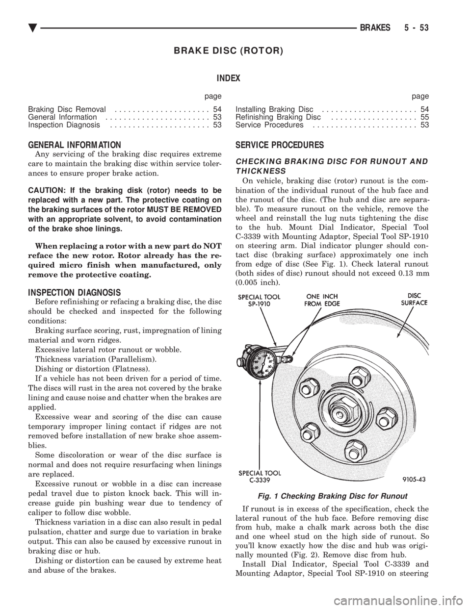
to the hub. Mount Dial Indicator, Special Tool
C-3339 with Mounting Adaptor, Special Tool SP-1910
on steering arm. Dial indicator plunger should con-
tact disc (braking surface) approximately one inch
from edge of disc (See Fig. 1). Check lateral runout
(both sides of disc) runout should not exceed 0.13 mm
(0.005 inch).
If runout is in excess of the specification, check the
lateral runout of the hub face. Before removing disc
from hub, make a chalk mark across both the disc
and one wheel stud on the high side of runout. So
you'll know exactly how the disc and hub was origi-
nally mounted (Fig. 2). Remove disc from hub. Install Dial Indicator, Special Tool C-3339 and
Mounting Adaptor, Special Tool SP-1910 on steering
Fig. 1 Checking Braking Disc for Runout
Ä BRAKES 5 - 53