1993 CHEVROLET PLYMOUTH ACCLAIM trip computer
[x] Cancel search: trip computerPage 423 of 2438

² To set DAY of WEEK, press TIME button. An ar-
row will appear on the display and point to the Day.
Press and hold the SET button to move the day for-
ward or INFO button to move it backward.
² To set DAY of MONTH, press TIME button. The
arrow will point to Date. Press and hold the SET
button to advance the date or INFO button to move
it backwards.
² To set MONTH of YEAR, press TIME button. The
arrow will point to the Month. Press and hold the
SET button to advance the Month forward or INFO
button to move backward. TEMP button, pressing the Temp button will dis-
play:
² The temperature outside the vehicle
² Vehicle direction define by an eight point compass
If Compass has lost calibration or not receiving
good information from the engine compartment node,
an asterisk (*) will flash on the display and the word
calibrate will appear. Refer to Compass Calibration. FUEL BUTTON, WILL DISPLAY:
² Pressing FUEL button the first time will show, the
estimated number of miles that can be driven with
the remaining fuel. The destination to empty indica-
tion will vary every few seconds as the amount of
fuel and fuel efficiency is calculated. This function
can not be reset.
² Pressing the FUEL button second time; will dis-
play the fuel consumed.
²
Pressing the FUEL button third time; will display
the average fuel economy in miles per gallon since last
reset. The display will be updated every 16 seconds.
² Pressing the FUEL button forth time, the current
fuel economy will be displayed. The current fuel
economy will be up updated every two seconds.
² To reset Fuel consumed, press SET button until
the fuel consumed message is displayed and then
within five seconds press SET button.
² To reset AVERAGE FUEL ECONOMY, press the
FUEL button until average fuel economy is displayed
and within five seconds press SET button. TRIP RESET, press FUEL button and wait four
seconds press the SET button twice. This clears all
trip information and the message Trip Reset will be
displayed. This will occur only if a reset function is
currently being displayed. The reset functions:
² Fuel consumed
² Average fuel economy message
INFO button, will active a MONITORED SYS-
TEMS OK message on display if all monitored sys-
tems are operating properly. If a problem is detected,
the appropriate message will be displayed. SET button, will clear the various functions after
they have been displayed. It is used to enter the
clock set or compass variance modes. This button is
also used to reset certain trip computer functions and
the maintenance reminder message.
The EVIC display may be turned off by pressing the
TIME and SET buttons at the same time. Pressing the
buttons a second time will restore the display.
EVIC INFORMATION SOURCES
The EVIC monitors information provided by the
body controller, engine compartment node and pow-
ertrain control module. Refer to Body Diagnostic Test
Procedure Manual for test procedures. The Body Controller is a micro-controller unit
which, informs the EVIC overhead console via the
CCD bus of:
² Time of day
² Day of week
² Day of month
² Month of year
² Fuel range
² Fuel consumed
² Fuel efficiency
² Warning messages as noted in Fig. 2
The Engine Compartment Node is a microcomputer
controlled unit which, informs the EVIC overhead
console via the CCD bus of:
² Outside temperature
² Compass direction
THE FOLLOWING ARE WARNING MESSAGES:
² Low brake fluid
² Low coolant level
² Low engine oil level
The powertrain control module is a microcomputer
controlled unit which, informs the EVIC overhead con-
sole via the CCD bus of the following warning messages:
² Engine temperature high
² Voltage improper
Fig. 2 EVIC Messages and Sensors
Ä OVERHEAD CONSOLE 8C - 7
Page 430 of 2438

dition exists. These messages are displayed on the
center of the instrument panel.For complete EVIC operating instructions, refer to
the Owners Manual provided with the vehicle.
EVIC BUTTON FUNCTIONS
TIME button will display:
² Time of day
² Day of week
² Day of month
² Month of year
² To set HOURS, press TIME button and within four
seconds press the SET button. An arrow will appear
on the display and point to the hours. Press and hold
the SET button to advance the hours or INFO button
to set back the hours.
² To set MINUTES, press TIME button. The arrow
will point to the minutes. Press and hold the SET
button to advance the minutes or INFO button to set
back the minutes.
² To set DAY of WEEK, press TIME button. An ar-
row will appear on the display and point to the Day.
Press and hold the SET button to move the day for-
ward or INFO button to move it backward.
² To set DAY of MONTH, press TIME button. The
arrow will point to Date. Press and hold the SET
button to advance the date or INFO button to move
it backwards.
² To set MONTH of YEAR, press TIME button. The
arrow will point to the Month. Press and hold the
SET button to advance the Month forward or INFO
button to move backward. TEMP button, pressing the Temp button will dis-
play:
² The temperature outside the vehicle
² Vehicle direction define by an eight point compass
If Compass has lost calibration or not receiving
good information from the engine compartment node,
an asterisk (*) will flash on the display and the word
calibrate will appear. Refer to Compass Calibration. FUEL BUTTON, WILL DISPLAY:
² Pressing FUEL button the first time will show, the
estimated number of miles that can be driven with
the remaining fuel. The destination to empty indica-
tion will vary every few seconds as the amount of
fuel and fuel efficiency is calculated. This function
can not be reset.
² Pressing the FUEL button second time; will dis-
play the fuel consumed.
² Pressing the FUEL button third time; will display
the average fuel economy in miles per gallon since
last reset. The display will be updated every 16 sec-
onds.
² Pressing the FUEL button forth time, the current
fuel economy will be displayed. The current fuel
economy will be up updated every two seconds. ²
To reset Fuel consumed, press SET button until
the fuel consumed message is displayed and then
within five seconds press SET button.
² To reset AVERAGE FUEL ECONOMY, press the
FUEL button until average fuel economy is displayed
and within five seconds press SET button. TRIP RESET, press FUEL button and wait four
seconds press the SET button twice. This clears all
trip information and the message Trip Reset will be
displayed. This will occur only if a reset function is
currently being displayed. The reset functions:
² Fuel consumed
² Average fuel economy message
INFO button, will active a MONITORED SYS-
TEMS OK message on display if all monitored sys-
tems are operating properly. If a problem is detected,
the appropriate message will be displayed. SET button, will clear the various functions after
they have been displayed. It is used to enter the
clock set or compass variance modes. This button is
also used to reset certain trip computer functions and
the maintenance reminder message. The EVIC display may be turned off by pressing
the TIME and SET buttons at the same time. Press-
ing the buttons a second time will restore the dis-
play.
EVIC INFORMATION SOURCES
The EVIC monitors information provided by the
body controller, engine compartment node and pow-
ertrain control module. Refer to Body Diagnostic Test
Procedure Manual for test procedures. The Body Controller is a micro-controller unit
which, informs the EVIC via the CCD bus of:
² Time of day
² Day of week
² Day of month
² Month of year
² Fuel range
² Fuel consumed
² Fuel efficiency
² Warning messages as noted in Fig. 3.
The Engine Compartment Node is a microcomputer
controlled unit which, informs the EVIC via the CCD
bus of:
² Outside temperature
² Compass direction
THE FOLLOWING ARE WARNING MESSAGES:
² Low brake fluid
² Low coolant level
² Low engine oil level
The powertrain control module is a microcomputer
controlled unit which, informs the EVIC via the CCD
bus of the following warning messages:
² Engine temperature high
² Voltage improper
8C - 14 OVERHEAD CONSOLE Ä
Page 494 of 2438
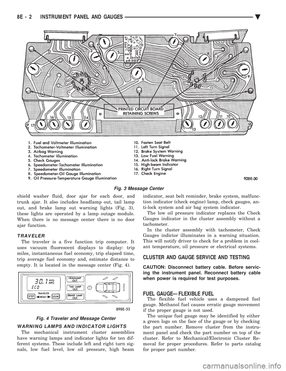
shield washer fluid, door ajar for each door, and
trunk ajar. It also includes headlamp out, tail lamp
out, and brake lamp out warning lights (Fig. 3),
these lights are operated by a lamp outage module.
When there is no message center there is no door
ajar function.
TRAVELER
The traveler is a five function trip computer. It
uses vacuum fluorescent displays to display: trip
miles, instantaneous fuel economy, trip elapsed time,
trip average fuel economy and, estimate distance to
empty. It is located in the message center (Fig. 4).
WARNING LAMPS AND INDICATOR LIGHTS
The mechanical instrument cluster assemblies
have warning lamps and indicator lights for ten dif-
ferent systems. These include left and right turn sig-
nals, low fuel level, low oil pressure, high beam indicator, seat belt reminder, brake system, malfunc-
tion indicator (check engine) lamp, check gauges, an-
ti-lock system and air bag system indicator. The low oil pressure indicator replaces the Check
Gauges indicator in the cluster assembly without a
tachometer. In the cluster assembly with tachometer, Check
Gauges indictor illuminates in a warning situation.
This will notify driver to check for a problem in cool-
ant temperature, oil pressure or electrical systems.
CLUSTER AND GAUGE SERVICE AND TESTING
CAUTION: Disconnect battery cable. Before servic-
ing the instrument panel. Reconnect battery cable
when power is required for test purposes.
FUEL GAUGEÐFLEXIBLE FUEL
The flexible fuel vehicle uses a dampened fuel
gauge. Methanol fuel causes erratic gauge movement
if the proper gauge is not used. The unique fuel gauge may be identified by either
a green logo on the face of the gauge or by checking
the part number. Remove cluster from the instru-
ment panel and check the part number on top of the
cluster. Refer to Mechanical/Electronic Cluster Re-
moval for proper procedures. Refer to parts catalog
for proper part number.
Fig. 3 Message Center
Fig. 4 Traveler and Message Center
8E - 2 INSTRUMENT PANEL AND GAUGES Ä
Page 933 of 2438
Wiring Diagram
Name Sheet Number
Illumination Lamp ...........................68
Resistor .................................68
Horn System ...............................65
Horn (Hi-Note) .............................65
Horn (Lo-Note) ............................65
Horn Relay ...............................65
Horn Switch ..............................65
Hydraulic Modulator (ABS) 41
Ignition Coil .......................... .14, 20, 29
Ignition Off-Draw Connector .....................5,7
Ignition Switch .............................4,11
Brake Warning Lamp Switch ....................11
Park Brake Switch ...........................11
Illuminated Entry .............................58
Illuminated Entry Module ......................58
Left Door Illuminated Entry Switch ................58
Right Door Illuminated Entry Switch ...............58
Illuminated Visor Vanity Mirror ....................73
Injector(s) ........................... .16, 17, 26
Instrument Panel Wiring to Left Body ...............123
Instrument Panel Wiring to Right Body ..............124
Instrument Panel to Multi-Function Switch ............116
Interface Grommet ............................47
Intermittent Wiper System .................... .63, 64
Intermittent Windshield Wiper Motor ...............64
Intermittent Wiper Control Module ................64
Multi-function Switch .........................63
Windshield Washer Low Fluid Level Sensor ...........63
Windshield Washer Pump Motor .................63
Key-In Switch ...............................46
Key-In Warning Chimes .........................45
Lamp Outage Module ........................ .115
Lamps A/C Lamps ...............................52
Ash Receiver Lamp ..........................52
Back-Up Lamps ............ .93, 94, 98, 102, 103, 105
Cargo Lamp ........................ .76, 96, 100
Center High Mounted Stop Lamp ........94, 98, 102, 105
Cigar Lighter Lamp ..........................52
Cluster Lamp ..............................77
Courtesy Lamps ............................76
Dome Lamp ..............................73
Fog Lamp-Left .............................56
Fog Lamp-Right ............................55
Front Reading Lamp .........................75
Glove Box Lamp ............................54
Halo Lamp ...............................54
Headlamp-Left .............................56
Headlamp Out Lamp .........................77
Headlamp-Right ............................55
Heater Lamp ..............................52
Illumination Lamp ..................... .68, 71, 72
Left Front Door Ajar Lamp .....................77
Left Rear Door Ajar Lamp ......................77
Left Side Marker Lamp ........................93
Left Tail/Stop and Turn Lamp ....................93
License Lamp ................... .93, 98, 102, 104Wiring Diagram
Name Sheet Number
Liftgate Ajar Lamp ..........................77
Low Washer Fluid Lamp .......................77
Park/Turn Lamp-Left .........................56
Park/Turn Lamp-Right ........................55
Radio Lamp ...............................52
Reading Lamps ............................75
Right Front Door Ajar Lamp ....................77
Right Rear Door Ajar Lamp .....................77
Seat Belt Warning Lamp .......................45
Side Marker Lamp-Left Front ....................56
Side Marker Lamp-Left Rear ...........93, 98, 102, 103
Side Marker Lamp-Right Front ...................55
Side Marker Lamp-Right Rear ..........94, 98, 102, 105
Stop Lamp Out Lamp ........................77
Tail Lamp Out Lamp .........................77
Tail/Stop Lamp-Left Rear ................... .93, 98
Tail/Stop Lamp-Right Rear .................. .94, 98
Tail/Stop and Turn Lamp-Left Rear .......93, 98, 102, 103
Tail/Stop and Turn Lamp-Right Rear ......94, 98, 102, 105
Transmission Range Indicator Lamp ...............76
Underhood Lamp ........................ .39, 40
Visor Vanity Mirror Lamp ......................73
Left Power Seat System ........................66
Center Switch .............................66
Front Switch ..............................66
Power Seat Motors ..........................66
Rear Switch ...............................66
License Lamp ..................... .93, 98, 102, 104
Lighter-Cigar ................................52
MAP Sensor .......................... .13, 19, 30
Message Center ..............................60
Traveler and Message Center ....................60
Mini Trip Computer ...........................60
Modules Airbag System Diagnostic Module .................47
Daytime Running Light Module ..................57
Illuminated Entry Module ......................58
Intermittent Wiper Control Module ................64
Lamp Outage Module ..................... .95, 99
Motors A/C-Heater Blower Motor ................... .71, 72
Fuel Pump Motor ...........................69
Heater Blower Motor .........................68
Idle Air Control Motor .................. .12, 18, 30
Intermittent Wiper Motor ......................64
Power Door Locks Motors .................. .85, 86
Power Seat Motors ..........................66
Power Window Motors .................... .81, 82
Radiator Fan Motor ...................... .32, 33
Starter Motor ............................9,10
Windshield Washer Pump Motor .................63
Name Brand Speaker Relay ......................89
Optical Horn Headlamp Dimmer Switch .............1,50
Overhead Console, Dome, Reading and Visor Vanity Lamps ..................... .73, 74, 75, 76
Ambient Temperature Sensor ....................75
Cargo Lamp ..............................76
Ä WIRING DIAGRAMS AA-BODY 8W - 183
Page 1290 of 2438
Wiring Diagram
Name Sheet Number
Optical Horn Switch .........................55
Park Brake Switch ...........................70
Park/Neutral Position Switch ...............13, 15, 38
Parking Switch .............................55
Power Door Lock Switch ..................115, 116
Power Mirror Switch ..................... .97, 99
Power Top Switch ...........................96
Power Window Switch ...................... .111
Reading Lamp Switch ................... .124, 126
Right Door Illuminated Entry Switch ..............109
Right Door Switch ......................... .110
Right Window Lift Switch .................... .111
Seat Belt Switch ....................... .101, 103
Transmission Range Switch ................15, 38, 59
Transmission Pressure Switch ...................36
Turn Signal Cancellation .......................56
Turn Signal Switch ..........................55
Vanity Lamp Switch ............118, 120, 122, 124, 126
Vehicle Speed Control Switch ...................59
Window Lift Switch ..................... .110, 111
Wing Switch ............................ .114
Wiper Switch ..............................66
Temperature Sending Unit .................... .40, 41
Transmission Control Module ...........15, 36, 37, 38, 39
Transmission Control Module Connector .............152
Transmission Pressure Switch .....................36
Transmission Range Switch ................... .15, 38
Trip Computer/EVIC ....................... .86, 171Wiring Diagram
Name Sheet Number
Trip Navigator ...............................87
Trunk Lamp ........................... .122, 124
Turbo III Fuel Injection Ignition System .........30, 31, 32,
33, 34, 35
Turn & Hazard Flasher System ...............56, 57, 58
Combo Flasher .............................56
Diode Package .............................56
Left Front Turn Signal Relay ....................57
Left Rear Turn Signal Relay .....................57
Right Front Turn Signal Relay ...................57
Right Rear Turn Signal Relay ....................57
Turn Signal Cancellation Switch ..................56
Underhood Lamp .............................16
Mercury Switch ............................16
Underhood Light ............................16
Vehicle Speed Control System .....................59
Clockspring ...............................59
Vehicle Speed Control Servo ....................59
Vehicle Speed Control Switch ...................59
Vehicle Speed Sensor .................... .21, 25, 35
Visual Message Center Connector ..................88
Windshield Wiper
termittent ...................66, 67
Low Fluid Level Sensor .......................67
Park Switch ...............................67
Washer Pump Motor .........................67
Wiper Motor ..............................66
Wiper Switch ..............................66
Washer Relay .............................66
8W - 540 WIRING DIAGRAMS AG-AJ BODY Ä
Page 2366 of 2438
AA BODY PROCEDURE
WARNING: IF EQUIPPED WITH A/C, THE REFRIG-
ERATION SYSTEM MUST BE COMPLETELY EMPTY
BEFORE PROCEEDING WITH THIS OPERATION. Refer to Group 8E and Group 23 for component re-
moval and installation when performing this opera-
tion. (1) Perform steps 1 through 7 of Blower Motor re-
moval and installation. (2) Remove relay panel above glove compartment
opening. (3) Disconnect the A/C vacuum line connector and
radio noise capacitor connectors. (4) Remove left windshield pillar trim cover.
(5) Remove left lower side cowl trim cover.
(6) Remove hood release handle mechanism attach-
ing screws. (7) Remove steering column trim covers.
(8) Disconnect parking brake release mechanism
connecting rod. Gain access through fuse panel open-
ing. (9) Remove lower left instrument panel silencer.
(10) Remove lower left instrument panel reinforce-
ment. (11) Remove instrument panel center (radio) bezel.
(12) Remove forward floor console.
(13) Remove the radio.
(14) Remove the heater-A/C control.
(15) Remove cigar lighter.
(16) Remove message center/trip computer, if
equipped. (17) Disconnect side window demister tubes from
top of heat A/C unit. (18) Remove steering column upper attaching bolts
and allow the steering wheel to rest on the driver
seat cushion. (19) Remove upper instrument panel (defroster
outlet) cover. (20) Remove upper instrument panel attaching
screws from below the windshield opening. (21) Loosen (do not remove) the left lower cowl in-
strument panel attaching screw. (22) Remove the right lower cowl instrument panel
attaching screw.
CAUTION: Protect the passenger seat cover from
soiling or damage using a suitable cover.
(23) Carefully pull the right side of the instrument
panel away from the vehicle. Allow the instrument
panel to rest on the passenger seat cushion.
CAUTION: Before proceeding with the next opera-
tion, review the Safety Precautions and Warnings at
the front of this Group. (24) From the engine compartment, drain the cool-
ing system and disconnect the heater hoses from the
heater core nipples. Plug the nipples to avoid spilling
coolant inside the vehicle. (25) Disconnect the refrigerant lines from the ex-
pansion-valve at the dash panel on the right side of
the vehicle. Seal the refrigerant lines to prevent con-
tamination. (26) Remove the expansion valve from the evapo-
rator plate. Seal the valve to avoid contamination. (27) Remove the condensate drain tube.
(28) Remove heater-A/C unit to dash panel attach-
ing nuts. (29) From inside the vehicle, pull rearward on the
heater-A/C unit to clear the dash panel silencer and
remove the unit from the vehicle. To install, reverse the preceding operation. Refill
cooling system and test for leaks. Evacuate and
charge the refrigerant system and test overall perfor-
mance.
AG, AJ BODY PROCEDURE
WARNING: IF EQUIPPED WITH A/C, THE REFRIG-
ERATION SYSTEM MUST BE COMPLETELY EMPTY
BEFORE PROCEEDING WITH THIS OPERATION.
(1) Disconnect the battery negative cable.
(2) Drain the coolant from cooling system. Refer to
Group 7, Cooling System. (3) Remove the air conditioner expansion valve (if
equipped). (4) Disconnect the heater hoses from heater core.
Then plug or cap the tubes on heater core. This will
prevent spilling coolant into the interior of vehicle
during unit removal. (5) Remove the condensate drain tube.
(6) Disconnect the A/C-heater vacuum supply line
from vacuum supply nipple (in the engine compart-
ment). (7) Remove the four A/C-heater assembly-to-dash
panel attaching nuts. (8) Remove the passenger side front seat. Refer to
Group 23, Body. (9) Remove the kick panel/sill cover at right door
opening. (10) Remove the body computer (Fig. 6) located at
the lower right section of the right front door pillar. (11) Remove the glove box assembly. Refer to
Group 8E, Instrument Panel. (12) Remove the carpeted panels from both sides of
the console. (13) Un-clip the radio antenna cable from the
metal support (Fig. 6) located behind and below the
glove box opening. (14) Instrument panel removal is not necessary to
remove the A/C-heater assembly from the vehicle.
24 - 62 HEATING AND AIR CONDITIONING Ä
Page 2372 of 2438
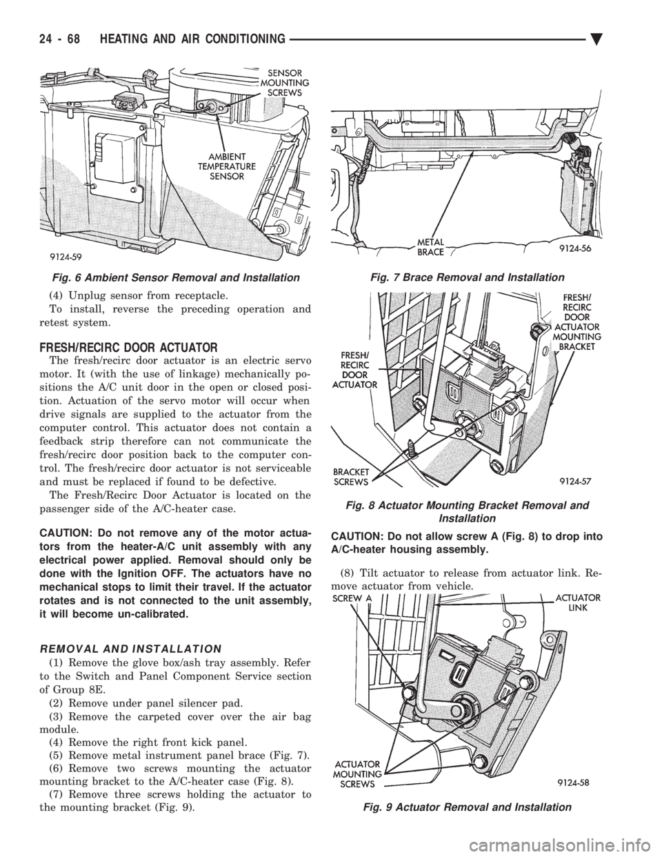
(4) Unplug sensor from receptacle.
To install, reverse the preceding operation and
retest system.
FRESH/RECIRC DOOR ACTUATOR
The fresh/recirc door actuator is an electric servo
motor. It (with the use of linkage) mechanically po-
sitions the A/C unit door in the open or closed posi-
tion. Actuation of the servo motor will occur when
drive signals are supplied to the actuator from the
computer control. This actuator does not contain a
feedback strip therefore can not communicate the
fresh/recirc door position back to the computer con-
trol. The fresh/recirc door actuator is not serviceable
and must be replaced if found to be defective. The Fresh/Recirc Door Actuator is located on the
passenger side of the A/C-heater case.
CAUTION: Do not remove any of the motor actua-
tors from the heater-A/C unit assembly with any
electrical power applied. Removal should only be
done with the Ignition OFF. The actuators have no
mechanical stops to limit their travel. If the actuator
rotates and is not connected to the unit assembly,
it will become un-calibrated.
REMOVAL AND INSTALLATION
(1) Remove the glove box/ash tray assembly. Refer
to the Switch and Panel Component Service section
of Group 8E. (2) Remove under panel silencer pad.
(3) Remove the carpeted cover over the air bag
module. (4) Remove the right front kick panel.
(5) Remove metal instrument panel brace (Fig. 7).
(6) Remove two screws mounting the actuator
mounting bracket to the A/C-heater case (Fig. 8). (7) Remove three screws holding the actuator to
the mounting bracket (Fig. 9). CAUTION: Do not allow screw A (Fig. 8) to drop into
A/C-heater housing assembly.
(8) Tilt actuator to release from actuator link. Re-
move actuator from vehicle.
Fig. 9 Actuator Removal and Installation
Fig. 6 Ambient Sensor Removal and InstallationFig. 7 Brace Removal and Installation
Fig. 8 Actuator Mounting Bracket Removal and Installation
24 - 68 HEATING AND AIR CONDITIONING Ä
Page 2373 of 2438
To install, reverse the preceding operation.
BLEND-AIR DOOR ACTUATOR
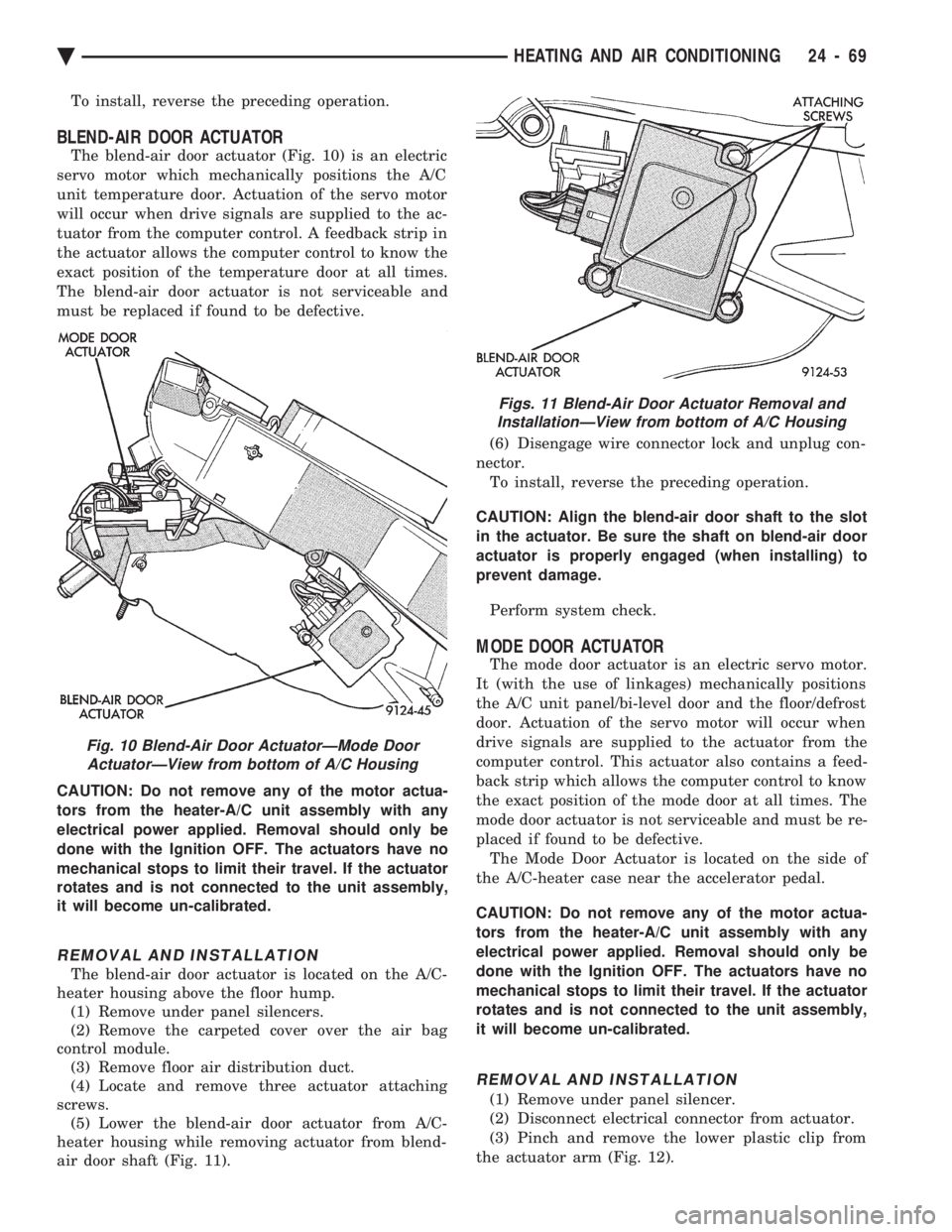
The blend-air door actuator (Fig. 10) is an electric
servo motor which mechanically positions the A/C
unit temperature door. Actuation of the servo motor
will occur when drive signals are supplied to the ac-
tuator from the computer control. A feedback strip in
the actuator allows the computer control to know the
exact position of the temperature door at all times.
The blend-air door actuator is not serviceable and
must be replaced if found to be defective.
CAUTION: Do not remove any of the motor actua-
tors from the heater-A/C unit assembly with any
electrical power applied. Removal should only be
done with the Ignition OFF. The actuators have no
mechanical stops to limit their travel. If the actuator
rotates and is not connected to the unit assembly,
it will become un-calibrated.
REMOVAL AND INSTALLATION
The blend-air door actuator is located on the A/C-
heater housing above the floor hump. (1) Remove under panel silencers.
(2) Remove the carpeted cover over the air bag
control module. (3) Remove floor air distribution duct.
(4) Locate and remove three actuator attaching
screws. (5) Lower the blend-air door actuator from A/C-
heater housing while removing actuator from blend-
air door shaft (Fig. 11). (6) Disengage wire connector lock and unplug con-
nector. To install, reverse the preceding operation.
CAUTION: Align the blend-air door shaft to the slot
in the actuator. Be sure the shaft on blend-air door
actuator is properly engaged (when installing) to
prevent damage.
Perform system check.
MODE DOOR ACTUATOR
The mode door actuator is an electric servo motor.
It (with the use of linkages) mechanically positions
the A/C unit panel/bi-level door and the floor/defrost
door. Actuation of the servo motor will occur when
drive signals are supplied to the actuator from the
computer control. This actuator also contains a feed-
back strip which allows the computer control to know
the exact position of the mode door at all times. The
mode door actuator is not serviceable and must be re-
placed if found to be defective. The Mode Door Actuator is located on the side of
the A/C-heater case near the accelerator pedal.
CAUTION: Do not remove any of the motor actua-
tors from the heater-A/C unit assembly with any
electrical power applied. Removal should only be
done with the Ignition OFF. The actuators have no
mechanical stops to limit their travel. If the actuator
rotates and is not connected to the unit assembly,
it will become un-calibrated.
REMOVAL AND INSTALLATION
(1) Remove under panel silencer.
(2) Disconnect electrical connector from actuator.
(3) Pinch and remove the lower plastic clip from
the actuator arm (Fig. 12).
Fig. 10 Blend-Air Door ActuatorÐMode Door ActuatorÐView from bottom of A/C Housing
Figs. 11 Blend-Air Door Actuator Removal andInstallationÐView from bottom of A/C Housing
Ä HEATING AND AIR CONDITIONING 24 - 69