1993 CHEVROLET PLYMOUTH ACCLAIM Wire diagram 89
[x] Cancel search: Wire diagram 89Page 364 of 2438
sends the message to the Engine Controller. The En-
gine Controller turns on the fan through the fan re-
lay. See Wiring Diagrams Manual for circuity and
diagnostics provided.Switching through the Engine Controller provides
fan control for the following conditions.
² The fan will not run during cranking until the en-
gine starts no matter what the coolant temperature
is.
² Fan will run when the air conditioning clutch is
engaged and low pressure cutout switch is closed.
² For 4 cylinder application the fan will run at ve-
hicle speeds above about 40 mph only if coolant tem-
perature reaches 110ÉC (230ÉF). It will turn off when
the temperature drops to 104ÉC (220ÉF). At speeds
below 40 mph the fan switches on at 102ÉC (215ÉF)
and off at 93ÉC (200ÉF).
² This is to help prevent steaming. The fan will run
only below 16ÉC (60ÉF) ambient. Between 38ÉC
(100ÉF) to 97ÉC (195ÉF) coolant temperature, at idle
and then only for three minutes.
RADIATOR FAN CONTROLÐAC/AY BODY V-6 ONLY
For this application, fan control is accomplished
based on coolant temperature, and on A/C head pres-
sure. These vehicles receive the variable displace-
ment compressor. The fan will go on when;
² Coolant temperature reaches 102ÉC (215ÉF) and off
at 93.4ÉC (200ÉF) regardless of vehicle speed.
² When the head pressure reaches 1516.9 kPa (220
psi) and turn off when the pressure reaches 1103 kPa
(160 psi).
TEMPERATURE GAUGE INDICATION
At idle the temperature gauge will rise slowly to
about 5/8 gauge travel. The fan will come on and the
gauge will drop to about 1/2 gauge travel, this is nor-
mal.
ELECTRIC FAN MOTOR
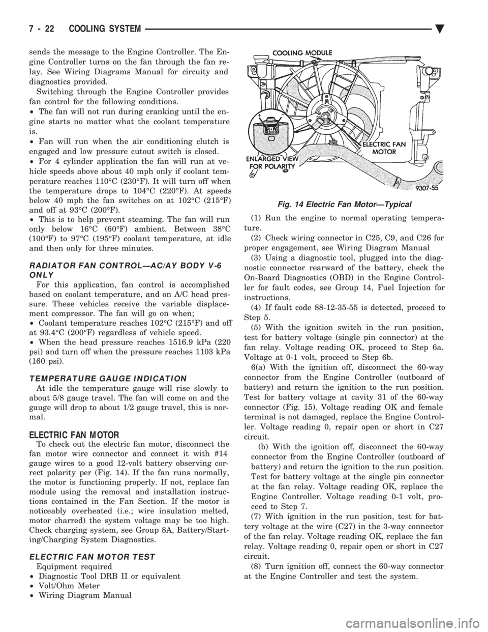
To check out the electric fan motor, disconnect the
fan motor wire connector and connect it with #14
gauge wires to a good 12-volt battery observing cor-
rect polarity per (Fig. 14). If the fan runs normally,
the motor is functioning properly. If not, replace fan
module using the removal and installation instruc-
tions contained in the Fan Section. If the motor is
noticeably overheated (i.e.; wire insulation melted,
motor charred) the system voltage may be too high.
Check charging system, see Group 8A, Battery/Start-
ing/Charging System Diagnostics.
ELECTRIC FAN MOTOR TEST
Equipment required
² Diagnostic Tool DRB II or equivalent
² Volt/Ohm Meter
² Wiring Diagram Manual (1) Run the engine to normal operating tempera-
ture. (2) Check wiring connector in C25, C9, and C26 for
proper engagement, see Wiring Diagram Manual (3) Using a diagnostic tool, plugged into the diag-
nostic connector rearward of the battery, check the
On-Board Diagnostics (OBD) in the Engine Control-
ler for fault codes, see Group 14, Fuel Injection for
instructions. (4) If fault code 88-12-35-55 is detected, proceed to
Step 5. (5) With the ignition switch in the run position,
test for battery voltage (single pin connector) at the
fan relay. Voltage reading OK, proceed to Step 6a.
Voltage at 0-1 volt, proceed to Step 6b. 6(a) With the ignition off, disconnect the 60-way
connector from the Engine Controller (outboard of
battery) and return the ignition to the run position.
Test for battery voltage at cavity 31 of the 60-way
connector (Fig. 15). Voltage reading OK and female
terminal is not damaged, replace the Engine Control-
ler. Voltage reading 0, repair open or short in C27
circuit. (b) With the ignition off, disconnect the 60-way
connector from the Engine Controller (outboard of
battery) and return the ignition to the run position.
Test for battery voltage at the single pin connector
at the fan relay. Voltage reading OK, replace the
Engine Controller. Voltage reading 0-1 volt, pro-
ceed to Step 7.
(7) With ignition in the run position, test for bat-
tery voltage at the wire (C27) in the 3-way connector
of the fan relay. Voltage reading OK, replace the fan
relay. Voltage reading 0, repair open or short in C27
circuit. (8) Turn ignition off, connect the 60-way connector
at the Engine Controller and test the system.
Fig. 14 Electric Fan MotorÐTypical
7 - 22 COOLING SYSTEM Ä
Page 443 of 2438
IGNITION SYSTEMS
CONTENTS
page page
2.2L TBI, 2.5L TBI, 2.5L MPI AND 3.0L IGNITION SYSTEMSÐDIAGNOSTIC PROCEDURES
..... 11
2.2L TBI, 2.5L TBI, 2.5L MPI AND 3.0L IGNI- TION SYSTEMSÐSERVICE PROCEDURES . 14
2.2L TBI, 2.5L TBI, 2.5L MPI AND 3.0L IGNI- TION SYSTEMSÐSYSTEM OPERATION .... 1
2.2L TURBO III, 3.3L AND 3.8L IGNITION SYSTEMÐDIAGNOSTIC PROCEDURES
.... 35
2.2L TURBO III, 3.3L AND 3.8L IGNITION SYSTEMÐSYSTEM OPERATION ......... 24
2.2L TURBO III, 3.3L AND 3.8L IGNITION SYSTEMSÐSERVICE PROCEDURES ...... 39
IGNITION SWITCH ...................... 45
SPECIFICATIONS ....................... 47
GENERAL INFORMATION
Throughout this group, references are made to par-
ticular vehicles by letter designation. A chart ex-
plaining the designations appears in the Introduction
Section of this manual.
2.2L TBI, 2.5L TBI, 2.5L MPI AND 3.0L IGNITION SYSTEMSÐSYSTEM OPERATION
INDEX
page page
Auto Shutdown (ASD) Relay and Fuel Pump Relay . 8
Coolant Temperature Sensor ................. 7
Distributor Cap ........................... 1
Distributor Pick-UpÐ3.0L Engine .............. 7
Distributor Pick-UpÐPCM Input ............... 6
General Information ........................ 1 Ignition Coil
.............................. 9
Manifold Absolute Pressure (MAP) Sensor ...... 8
Powertrain Control Module (PCM) ............. 6
Rotor .................................. 2
Spark Plug Cables ........................ 2
Spark Plugs ............................. 3
GENERAL INFORMATION
This section describes the ignition systems of the
2.2L TBI, 2.5L TBI, 2.5L MPI (flexible fuel AA-body)
and 3.0L engines. The Fuel Injection sections of Group 14 explain On
Board Diagnostics. Group 0, Lubrication and Maintenance, contains
general maintenance information for ignition related
items. The Owner's Manual also contains mainte-
nance information.
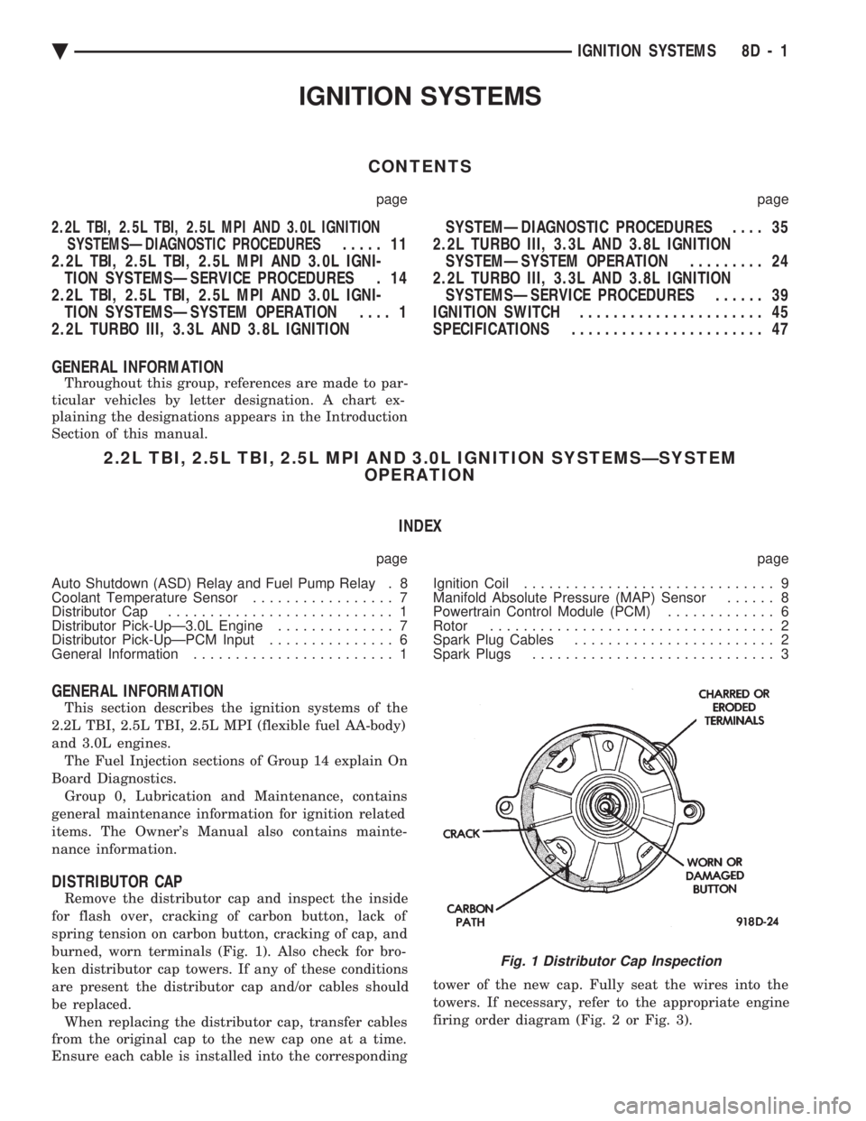
DISTRIBUTOR CAP
Remove the distributor cap and inspect the inside
for flash over, cracking of carbon button, lack of
spring tension on carbon button, cracking of cap, and
burned, worn terminals (Fig. 1). Also check for bro-
ken distributor cap towers. If any of these conditions
are present the distributor cap and/or cables should
be replaced. When replacing the distributor cap, transfer cables
from the original cap to the new cap one at a time.
Ensure each cable is installed into the corresponding tower of the new cap. Fully seat the wires into the
towers. If necessary, refer to the appropriate engine
firing order diagram (Fig. 2 or Fig. 3).
Fig. 1 Distributor Cap Inspection
Ä
IGNITION SYSTEMS 8D - 1
Page 479 of 2438

FAILURE TO START TEST
This no-start test checks the camshaft position sen-
sor and crankshaft position sensor. The powertrain control module (PCM) supplies 8.0
volts to the camshaft position sensor and crankshaft
position sensor through one circuit. If the 8.0-volt
supply circuit shorts to ground, neither sensor will
produce a signal (output voltage to the PCM). When the ignition key is turned and left in the On
position , the PCM automatically energizes the auto shutdown (ASD) relay. However, the PCM de-energizes
the relay within one second because it has not received
a crankshaft position sensor signal indicating engine
rotation.
During cranking, the ASD relay will not energize
until the PCM receives a crankshaft signal. Secondly,
the ASD relay remains energized only if the PCM
senses a camshaft position sensor signal immediately
after detecting the crankshaft position sensor signal. (1) Check battery voltage. Voltage should approxi-
mately 12.66 volts or higher to perform failure to start
test. (2) Disconnect the harness connector from the coil
pack (Fig. 2). (3) Connect a test light to the B+ (battery voltage)
terminal of the coil electrical connector and ground.
The wire for the B+ terminal is dark green with a black
tracer. (4) Turn the ignition key to the ON position.The
test light should flash On and then Off. Do not turn
the Key to off position, leave it in the On position .
(a) If the test light flashes momentarily, the PCM
grounded the auto shutdown (ASD) relay. Proceed to
step 5. (b) If the test light did not flash, the ASD relay did
not energize. The cause is either the relay or one of
the relay circuits. Use the DRBII scan tool to test the
ASD relay and circuits. Refer to the appropriate
Powertrain Diagnostics Procedure Manual. Refer to
the wiring diagrams section for circuit information.
(5) Crank the engine. If the key was placed in the off
position after step 4, place the key in the On position
before cranking. Wait for the test light to flash once,
then crank the engine. (a) If the test light momentarily flashes during
cranking, the PCM is not receiving a camshaft posi-
tion sensor signal. Use the DRBII scan tool to test the
camshaft position sensor and sensor circuits. Refer to
the appropriate Powertrain Diagnostics Procedure
Manual. Refer to the wiring diagrams section for
circuit information. (b) If the test light did not flash during cranking,
unplug the camshaft position sensor connector. Turn
the ignition key to the off position. Turn the key to
the On position, wait for the test light to momen-
tarily flash once, then crank the engine. If the test
light momentarily flashes, the camshaft position
sensor is shorted and must be replaced. If the light
did not flash, the cause of the no-start is in either the
crankshaft position sensor/camshaft position sensor
8.0-volt supply circuit, or the crankshaft position
sensor 5-volt output or ground circuits. Use the
DRBII scan tool to test the crankshaft position sen-
sor and the sensor circuits.
Fig. 6 Ignition Coil Electrical Connection
Fig. 7 Ignition Coil Terminal Identification
Fig. 8 Checking Ignition Coil Secondary Resistance
Ä IGNITION SYSTEMS 8D - 37
Page 480 of 2438

Refer to the appropriate Powertrain Diagnostics Pro-
cedure Manual. Refer to the wiring diagrams section
for circuit information.
COOLANT TEMPERATURE SENSOR TEST
(1) With key off, disconnect wire connector from
coolant temperature sensor (Fig. 9).
(2) Connect one lead of ohmmeter to one terminal of
coolant temperature sensor. (3) Connect the other lead of ohmmeter to remaining
terminal of coolant temperature sensor. The ohmmeter
should read as follows;
² Engine/Sensor hot at normal operating temperature
around 200ÉF should read approximately 700 to 1,000
ohms.
² Engine/Sensor at room temperature around 70ÉF,
ohmmeter should read approximately 7,000 to 13,000
ohms. To test the coolant temperature sensor circuits,
refer to the DRBII scan tool and the appropriate
Powertrain Diagnostic Service manual.
MANIFOLD ABSOLUTE PRESSURE (MAP) SENSOR
TEST
Refer to the appropriate Powertrain Diagnostic Pro-
cedure manual.
CRANKSHAFT POSITION SENSOR AND CAMSHAFT
POSITION SENSOR TESTS
Refer to the appropriate Powertrain Diagnostic Pro-
cedure manual.
Fig. 9 Coolant Temperature Sensor Test
8D - 38 IGNITION SYSTEMS Ä
Page 520 of 2438
or bind the transmission range indicator guide tube
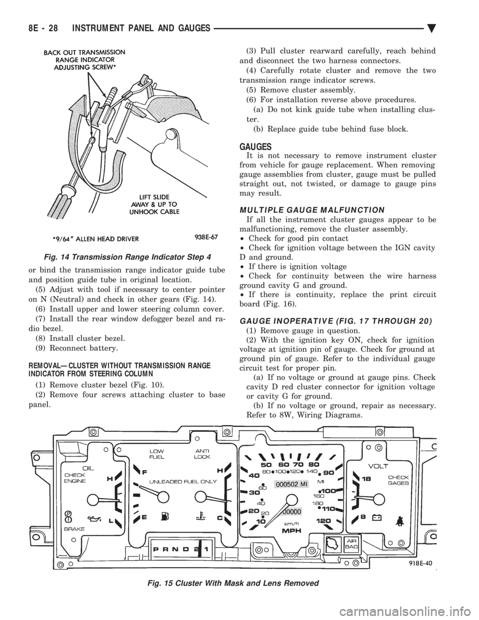
and position guide tube in original location.(5) Adjust with tool if necessary to center pointer
on N (Neutral) and check in other gears (Fig. 14). (6) Install upper and lower steering column cover.
(7) Install the rear window defogger bezel and ra-
dio bezel. (8) Install cluster bezel.
(9) Reconnect battery.
REMOVALÐCLUSTER WITHOUT TRANSMISSION RANGE
INDICATOR FROM STEERING COLUMN
(1) Remove cluster bezel (Fig. 10).
(2) Remove four screws attaching cluster to base
panel. (3) Pull cluster rearward carefully, reach behind
and disconnect the two harness connectors. (4) Carefully rotate cluster and remove the two
transmission range indicator screws. (5) Remove cluster assembly.
(6) For installation reverse above procedures. (a) Do not kink guide tube when installing clus-
ter. (b) Replace guide tube behind fuse block.
GAUGES
It is not necessary to remove instrument cluster
from vehicle for gauge replacement. When removing
gauge assemblies from cluster, gauge must be pulled
straight out, not twisted, or damage to gauge pins
may result.
MULTIPLE GAUGE MALFUNCTION
If all the instrument cluster gauges appear to be
malfunctioning, remove the cluster assembly.
² Check for good pin contact
² Check for ignition voltage between the IGN cavity
D and ground.
² If there is ignition voltage
² Check for continuity between the wire harness
ground cavity G and ground.
² If there is continuity, replace the print circuit
board (Fig. 16).
GAUGE INOPERATIVE (FIG. 17 THROUGH 20)
(1) Remove gauge in question.
(2) With the ignition key ON, check for ignition
voltage at ignition pin of gauge. Check for ground at
ground pin of gauge. Refer to the individual gauge
circuit test for proper pin. (a) If no voltage or ground at gauge pins. Check
cavity D red cluster connector for ignition voltage
or cavity G for ground. (b) If no voltage or ground, repair as necessary.
Refer to 8W, Wiring Diagrams.
Fig. 15 Cluster With Mask and Lens Removed
Fig. 14 Transmission Range Indicator Step 4
8E - 28 INSTRUMENT PANEL AND GAUGES Ä
Page 606 of 2438

Electronic vehicle speed control may be tested us-
ing two different methods. One involves use of a
DRB II. If this test method is desired, refer to the
Powertrain Diagnostic Test Procedures for charging
and vehicle speed control manual. The other test method uses a volt/ohm meter and is
described in the following tests. If any information is needed concerning wiring, re-
fer to Group 8W, Wiring Diagrams.
CAUTION: When test probing for voltage or conti-
nuity at electrical connectors, care must be taken
not to damage connector, terminals, or seals. If
these components are damaged, intermittent or
complete system failure may occur.
SERVO ELECTRICAL TESTS
WARNING: ON VEHICLES EQUIPPED WITH AIR-
BAG, SEE GROUP 8M, RESTRAINT SYSTEMS FOR
AIRBAG, STEERING WHEEL OR COLUMN RE-
MOVAL PROCEDURES.
(1) Turn ignition switch to the ON position. With
the vehicle speed control switch in the ON position,
set up a voltmeter to read battery voltage and con-
nect the negative lead to a good chassis ground. (2) Disconnect the four-way connector going to the
servo (Fig. 12). Test pin 2 of the main harness four-
way connector for battery voltage. If not OK go to
step 3. If voltage is OK go to step 4. (3) Perform the following tests.(a) Disconnect the six-way connector at the stop
lamp switch and test pin 1 of the main harness for
battery voltage. If voltage is OK perform the stop
lamp switch test. (b) If the stop lamp switch tests OK; repair wire
between the servo and the stop lamp switch. (c) If no voltage at pin 1 at the 6-way stop lamp
connector, remove the vehicle speed control switch
and disconnect the four-way connector. Test pin 1
of main harness for battery voltage. (d) If voltage is OK perform the vehicle speed
control switch test. (e) If vehicle speed control switch is OK, test
continuity across the clockspring. (f) If clockspring OK, repair as required, wire be-
tween stop lamp switch and clockspring. (g) If no voltage at pin 1 of the 4-way vehicle
speed control switch connector.
² Test for battery voltage between the ignition and
the fuse
² If voltage OK, check fuse
² If fuse OK, repair wire between fuse and clock-
spring
Fig. 7 Vehicle Speed ControlÐAC & AY Bodies with 3.0L
8H - 4 VEHICLE SPEED CONTROL Ä
Page 626 of 2438
CONDITION: MOTOR WILL STOP WHEREVER IT IS, WHEN COLUMN SWITCH IS PUT IN OFFPOSITION. THE WIPERS DO NOT CONTINUERUNNING TO PARK POSITION
PROCEDURE
(1) Remove motor wiring connector and clean ter-
minals. Reconnect connector and test motor.If prob-
lem persists, proceed to Step 2. (2) Set wiper switch to OFF position. Disconnect
motor wiring connector. Connect a voltmeter or test
lamp to the motor ground strap. Connect the other
lead to terminal 2 of wiring connector. (a) If voltage is not present, check for an open
circuit in the wiring harness or wiper control
switch. (b) If voltage is present, proceed to step 3.
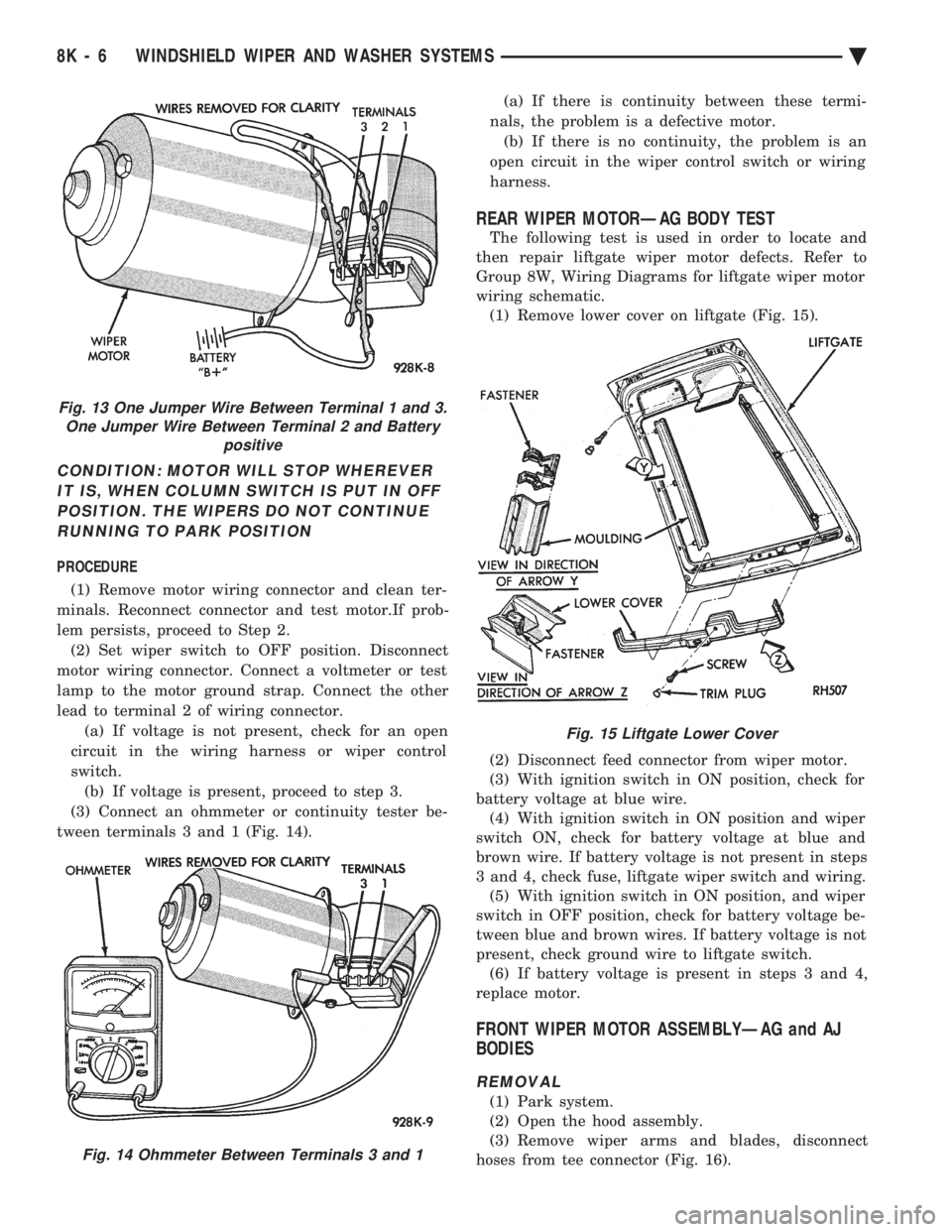
(3) Connect an ohmmeter or continuity tester be-
tween terminals 3 and 1 (Fig. 14). (a) If there is continuity between these termi-
nals, the problem is a defective motor. (b) If there is no continuity, the problem is an
open circuit in the wiper control switch or wiring
harness.
REAR WIPER MOTORÐAG BODY TEST
The following test is used in order to locate and
then repair liftgate wiper motor defects. Refer to
Group 8W, Wiring Diagrams for liftgate wiper motor
wiring schematic. (1) Remove lower cover on liftgate (Fig. 15).
(2) Disconnect feed connector from wiper motor.
(3) With ignition switch in ON position, check for
battery voltage at blue wire. (4) With ignition switch in ON position and wiper
switch ON, check for battery voltage at blue and
brown wire. If battery voltage is not present in steps
3 and 4, check fuse, liftgate wiper switch and wiring. (5) With ignition switch in ON position, and wiper
switch in OFF position, check for battery voltage be-
tween blue and brown wires. If battery voltage is not
present, check ground wire to liftgate switch. (6) If battery voltage is present in steps 3 and 4,
replace motor.
FRONT WIPER MOTOR ASSEMBLYÐAG and AJ
BODIES
REMOVAL
(1) Park system.
(2) Open the hood assembly.
(3) Remove wiper arms and blades, disconnect
hoses from tee connector (Fig. 16).
Fig. 13 One Jumper Wire Between Terminal 1 and 3. One Jumper Wire Between Terminal 2 and Battery positive
Fig. 14 Ohmmeter Between Terminals 3 and 1
Fig. 15 Liftgate Lower Cover
8K - 6 WINDSHIELD WIPER AND WASHER SYSTEMS Ä
Page 643 of 2438
LAMPS
CONTENTS
page page
BULB APPLICATION TABLE ............... 38
CONCEALED HEADLAMPS ................ 27
EXTERIOR LAMP SWITCHES AND HEADLAMP ALIGNMENT ........................... 3
EXTERIOR LAMP SYSTEMS .............. 25
EXTERIOR LAMPSÐAA BODY ............. 7
EXTERIOR LAMPSÐAC BODY ............ 10 EXTERIOR LAMPSÐAG BODY
............ 14
EXTERIOR LAMPSÐAJ BODY ............ 16
EXTERIOR LAMPSÐAP BODY ............ 19
EXTERIOR LAMPSÐAY-BODY ............ 22
GENERAL INFORMATION .................. 1
ILLUMINATED ENTRY SYSTEM ........... 33
GENERAL INFORMATION
Each vehicle is equipped with lamps used for illumi-
nating and indicating purposes. A circuit must have a
good ground to be complete. Circuit ground occurs
when the lamp socket makes contact with the metal
body. On vehicles with plastic lamps, a wire between
the socket and the body makes the grounds. When changing lamp bulbs, check the socket for
corrosion. If corrosion is present, clean contacts with a
wire brush and coat the inside of the socket with
Mopar tMulti-purpose Grease or equivalent.
CAUTION: Do not touch the glass of halogen bulbs
with fingers or any possibly oily surface, reduced
bulb life will result.
BODY IDENTIFICATION
Throughout this Group, references are made to the
vehicle family or body code. To decode the vehicle
identification plates, refer to the Introduction Section
at the front of this manual.
DIAGNOSTIC PROCEDURES
Begin electrical system failure diagnosis by testing
all related fuses and circuit breakers in the fuse block
and engine compartment. When a vehicle experiences problems with the head-
lamp system, verify the condition of the battery con-
nections, charging system, headlamp bulbs, wire con-
nectors, relay, high beam dimmer switch and headlamp
switch. Refer to Wiring Diagrams manual for compo-
nent locations and circuit information.
SYMPTOM
Headlamps are dim when engine is idling of
with ignition turned OFF. Canada cars must
have lamps ON. ACTION
² Clean battery terminal clamps and posts. Refer to
Group 8B, Battery/Starter/Generator Service for
proper procedures.
² Test charging system output. Refer to Group 8A,
Battery/Starting/Charging Systems Diagnostics for
proper testing procedures.
² Test for high resistance in headlamp circuits.
² Defective headlamp bulb.
SYMPTOM
Bulbs burn out frequently.
ACTION
² Test charging system output. Refer to Group 8A,
Battery/Starting/Charging Systems Diagnostics for
proper testing procedures.
² Check for loose or corroded connector terminals or
splices in headlamp circuits. Refer to Wiring Diagrams
manual for component and splice locations.
SYMPTOM
Headlamps are dim with engine running above
idle. Canada cars must have lamps ON.
ACTION
² Test charging system output. Refer to Group 8A,
Battery/Starting/Charging Systems Diagnostics for
proper testing procedures.
² Test for high resistance in headlamp circuits.
² Defective headlamp bulb.
SYMPTOM
Headlamps flash randomly.
ACTION
² Test for poor circuit ground.
² Test for high resistance in headlamp circuits.
Ä LAMPS 8L - 1