1993 CHEVROLET PLYMOUTH ACCLAIM Wire diagram 89
[x] Cancel search: Wire diagram 89Page 699 of 2438
to the deck lid open position. If the pull down limit
switch is depressed at this time, the motor should
stop.(c) If these results are not obtained, replace the
pull down motor assembly.
REMOTE KEYLESS ENTRY
OPERATION
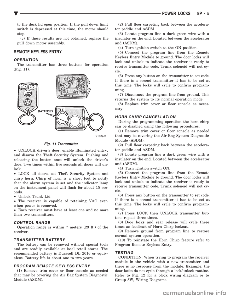
The transmitter has three buttons for operation
(Fig. 11).
² UNLOCK driver's door, enable illuminated entry,
and disarm the Theft Security System. Pushing and
releasing the button once will unlock the driver's
door. Two times within five seconds all doors will un-
lock.
² LOCK all doors, set Theft Security System and
chirp horn. Chirp of horn is a short toot to notify
that the alarm system is set and the indicator lamp
on the instrument panel will flash for about 15 sec-
onds.
² Unlock Trunk Lid
² The receiver is capable of retaining VAC even
when power is removed.
² Each receiver must have at least one and no more
than two transmitters.
CONTROL RANGE
Operation range is within 7 meters (23 ft.) of the
receiver.
TRANSMITTER BATTERY
The battery can be removed without special tools
and are readily available at local retail stores. The
recommended battery is Duracell DL 2016 or equiv-
alent. Battery life is about one to two years.
PROGRAM REMOTE KEYLESS ENTRY
(1) Remove trim cover or floor console as needed
that may be covering the Air Bag System Diagnostic
Module (ASDM). (2) Pull floor carpeting back between the accelera-
tor peddle and ASDM. (3) Locate program line a dark green wire with a
insulator on the end. Located between the accelerator
and (ASDM). (4) Turn ignition switch to the ON position.
(5) Connect the program line from the Remote
Keyless Entry Module to ground. The door locks will
lock and unlock to indicate the receiver is ready to
receive transmitter code. Trunk solenoid will not cy-
cle. (6) Press any button on the transmitter to set code.
If there is a second transmitter it has to be set at
this time. The locks will cycle to confirm program-
ming. (7) Disconnect the program line from ground. This
returns the system to its normal operation mode. (8) Replace trim cover or floor console as neces-
sary.
HORN CHIRP CANCELLATION
During the programming operation the horn chirp
can be disabled using the following procedures: (1) Remove trim cover or floor console as needed
that may be covering the Air Bag System Diagnostic
Module (ASDM). (2) Pull floor carpeting back between the accelera-
tor peddle and ASDM. (3) Locate program line a dark green wire with a
insulator on the end. Located between the accelerator
and (ASDM). (4) Turn ignition switch ON.
(5) Connect the program line from the Remote
Keyless Entry Module to ground. The door locks will
lock and unlock to indicate the receiver is ready to
receive transmitter code. Trunk solenoid will not cy-
cle. (6) Press any button on the transmitter to set code.
If there is a second transmitter it has to be set at
this time. The locks will cycle to confirm program-
ming. (7) Press LOCK then UNLOCK transmitter but-
tons repeat three times. (8) Door locks and rear release will cycle three
times as feedback of Horn Chirp lockout. (9) Remove ground from program line to restore
normal system operation. (10) To reinstate the Horn Chirp feature refer to
Program Remote Keyless Entry.
TESTING
CONDITION: When trying to program the receiver
module in the vehicle with a new transmitter and
there is no response from the module, Example: the
door locks do not cycle through a lock/unlock routine.
Refer to Fig. 12 for a block wiring diagram or to
Group 8W, Wiring Diagrams.
Fig. 11 Transmitter
Ä POWER LOCKS 8P - 5
Page 727 of 2438
POWER WINDOWS
CONTENTS
page page
BENCH REPAIR OF REGULATOR AND MOTOR CONVENTIONAL REGULATORS .......... 5
GEAR AND PINION REPLACEMENT AND LUBRICATION ....................... 3
GENERAL INFORMATION .................. 1
MOTOR REPLACEMENT ................... 7
MOTOR REPLACEMENT CONVENTIONAL REGULATORS ....................... 3
MOTOR REPLACEMENTÐFLEX DRIVE REGULATORS ......................... 5 POWER WINDOW CABLE HOUSING/MOTOR RE-
PLACEMENTÐAC and AY BODIES ........ 7
QUARTER WINDOW MOTOR REPLACEMENTÐ AJ BODY ............................. 9
QUARTER WINDOW REPLACEMENTÐ AJ BODY ............................. 8
WINDOW LIFT MOTOR TEST .............. 1
WINDOW LIFT SWITCH TEST .............. 1
WIRING VOLTAGE TEST .................. 1
GENERAL INFORMATION
Front and rear door window lift motors are of the
permanent magnet type. A positive and negative bat-
tery connection to either of the two motor terminals
will cause the motor to rotate in one direction. Re-
versing current through these same two connections
will cause the motor to rotate in the opposite direc-
tion. Each individual motor is grounded through the
master switch by a black wire attached to the left
cowl panel. It is necessary that the window be free to slide up
and down in the glass channels or tubes and tracks.
If the window is not free to move up and down, the
window lift motor will not be able to move the glass. To determine if the glass is free is to disconnect the
regulator from the glass lift plate, and slide the win-
dow up and down by hand. For conventional arm-sec-
tor regulators, after the lift plate is detached from
the glass, it will slide off the regulator drive arm.
Flex-drive regulators may be detached the same way
or by removing one screw holding the flex rack to the
lift plate drive arm.
WIRING VOLTAGE TEST
The following wiring test determines whether or
not voltage is continuous through the body harness
to switch. After removing switch for testing purposes, care-
fully separate multiple terminal block on wiring har-
ness from switch body. With ignition switch ON
connect one lead of test light to black (or gray) wire
terminal and touch other test light lead to tan wire
terminal. If the test light comes on, the wiring cir-
cuit between the battery and switch is functional. If
light does not come on, check 30 amp main fuse (cir- cuit breaker) or for a broken wire. For wiring, spe-
cific connector type and location, refer to Group 8W,
Wiring Diagrams.
WINDOW LIFT SWITCH TEST
For switch testing, remove the switch from its
mounting. Using an ohmmeter, refer to Window
Switch Continuity Charts to determine if continuity
is correct. If the results are not obtained, replace the
switch. AC and AY Bodies are equipped with an Auto-
Down feature. This feature allows the operator to
lower the driver's window without having to hold the
switch in the down position. The Auto-Down feature
can be activated by pressing the down switch past
the first detent (Stop). To test the auto-down feature, operate the window
in the normal up and down mode. If the window
works correctly in the normal mode, but not in the
auto-down mode, replace the switch. To test the window switch (other than Auto-Down
mode), install a known good switch.
WINDOW LIFT MOTOR TEST
(1) Connect positive (+) lead from a test battery to
either of the two motor terminals. (2) Connect negative (-) lead from test battery to
remaining motor terminal. (3) The motor should now rotate in one direction to
either move window up or down. (a) If window happens to already be in full UP
position and motor is connected so as to rotate in
UP direction no movement will be observed. (b) Likewise, motor connected to DOWN direc-
tion rotation, no movement will be observed if win-
dow is already in full DOWN position.
Ä POWER WINDOWS 8S - 1
Page 744 of 2438
(2) The headlamps and parking lamps should turn
ON for about five seconds.
² AUTO MIRROR LED
² DARK LED
² AUTO LAMP LED
² The LED indicators blink for about 5 seconds.
² If the three indicators continue to blink consider-
ably longer than 5 seconds, then the mirror assembly
is defective. (3) The mirror should change to dim state.(a) Place shift selector in reverse (R), with igni-
tion switch ON:
² AUTO MIRROR LED indicator ON
² DARK LED indicator flashing
² Lasting about 15 seconds
(b) The mirror should slowly change to bright
state. (c) If the ignition is not turned OFF within the
15 second time period, the mirror will reset to its
previous setting.
The previous conditions are OK, the mirror is op-
erating properly. If not OK, continue with voltage tests below.
VOLTAGE TEST
To test for voltage insert voltmeter probe into wire
end of connector to contact terminal. Pin 1 ignition voltage (a) Ignition switch OFF, zero volts.
(b) Ignition switch ON, battery voltage.
Pin 2 battery voltage (a) Battery voltage at all times.
(b) No voltage, check 15 amp. fuse.
Pin 3 Ground (a) Continuity to ground.
(b) No voltage
Pin 4 Reverse over-ride (a) Ignition OFF, zero voltage.
(b) Ignition ON shift selector in Reverse (R), bat-
tery voltage. (c) Ignition ON shift selector in any position
other than Reverse (R), zero voltage.
Pin 5 Headlamp relay (a) Battery voltage at all times from headlamp
relay. (b) No battery voltage, test headlamp relay.
Pin 6 Park lamp relay (a) Ignition switch ON, battery voltage feed from
park lamp relay. (b) Ignition switch OFF, zero voltage.
(c) Ignition ON, No battery voltage test park
lamp relay.
If Voltage Test are OK, replace mirror assembly.
If not OK, refer to Wiring Diagrams manual.
8T - 8 POWER MIRRORS Ä
Page 751 of 2438
GENERAL INFORMATION
CONTENTS
page page
CIRCUIT IDENTIFICATION ................. 3
COMPONENT IDENTIFICATION ............. 3
CONNECTORS ........................... 4
FUSIBLE LINKS ......................... 4
HARNESS REPAIR ....................... 4
LOCATING A SYSTEM .................... 3 SECONDARY IGNITION WIRING
............ 1
SPLICE LOCATIONS ...................... 3
SYMBOLS, FUSES AND RELAYS ........... 7
TROUBLESHOOTING WIRING PROBLEMS .... 4
WIRE CODE IDENTIFICATION .............. 2
WIRING DIAGRAM SHEETS AND INDEXES . . . 1
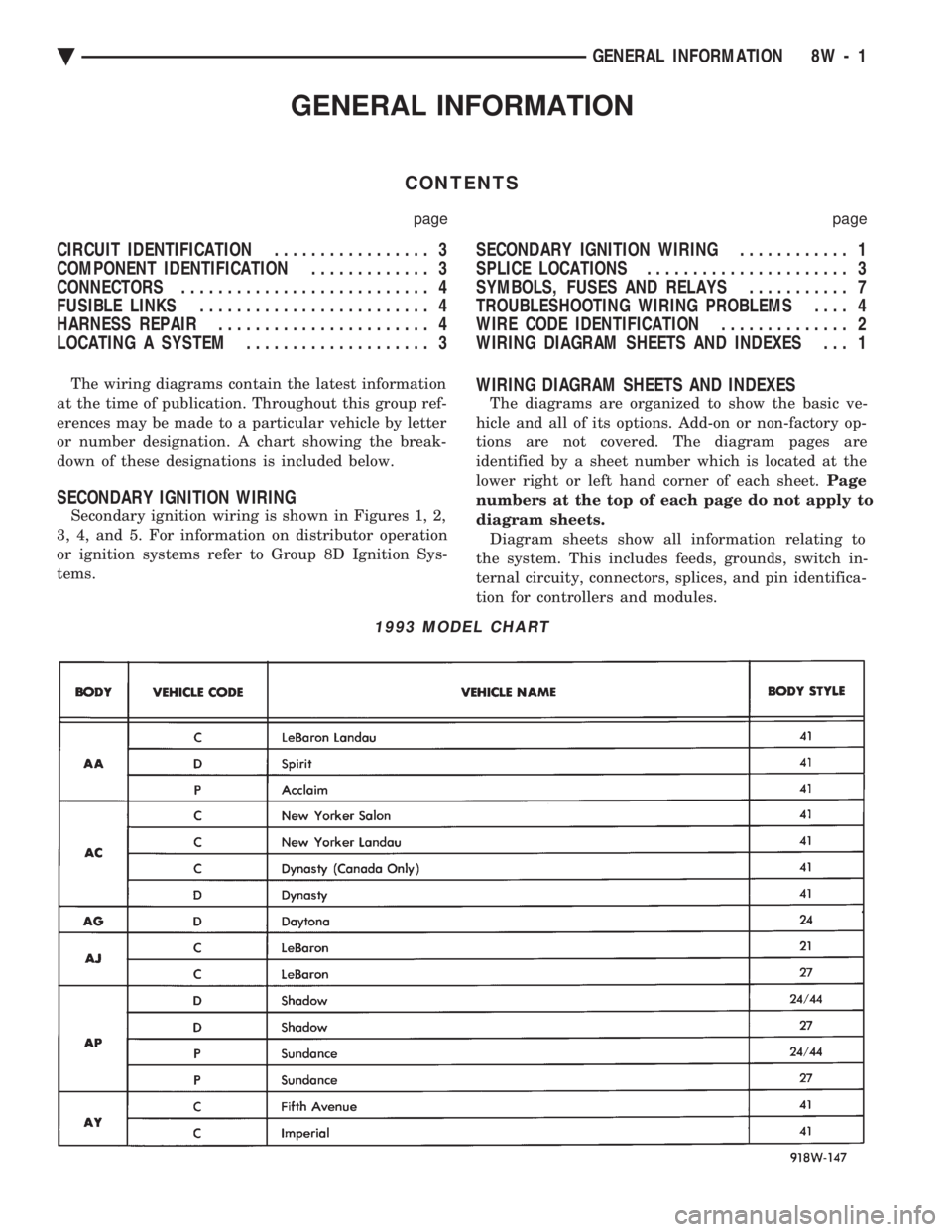
The wiring diagrams contain the latest information
at the time of publication. Throughout this group ref-
erences may be made to a particular vehicle by letter
or number designation. A chart showing the break-
down of these designations is included below.
SECONDARY IGNITION WIRING
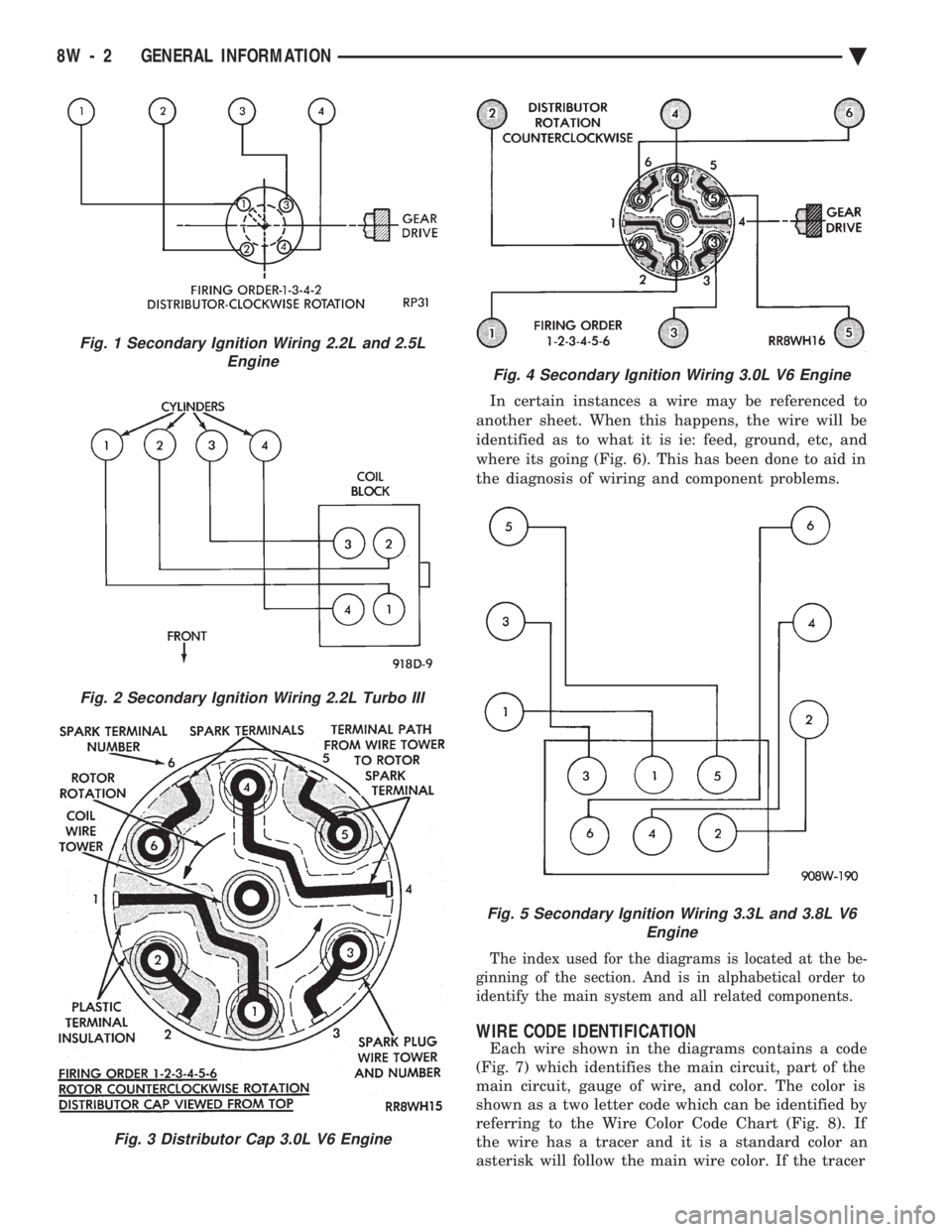
Secondary ignition wiring is shown in Figures 1, 2,
3, 4, and 5. For information on distributor operation
or ignition systems refer to Group 8D Ignition Sys-
tems.
WIRING DIAGRAM SHEETS AND INDEXES
The diagrams are organized to show the basic ve-
hicle and all of its options. Add-on or non-factory op-
tions are not covered. The diagram pages are
identified by a sheet number which is located at the
lower right or left hand corner of each sheet. Page
numbers at the top of each page do not apply to
diagram sheets. Diagram sheets show all information relating to
the system. This includes feeds, grounds, switch in-
ternal circuity, connectors, splices, and pin identifica-
tion for controllers and modules.
1993 MODEL CHART
Ä GENERAL INFORMATION 8W - 1
Page 752 of 2438
In certain instances a wire may be referenced to
another sheet. When this happens, the wire will be
identified as to what it is ie: feed, ground, etc, and
where its going (Fig. 6). This has been done to aid in
the diagnosis of wiring and component problems.
The index used for the diagrams is located at the be-
ginning of the section. And is in alphabetical order to
identify the main system and all related components.
WIRE CODE IDENTIFICATION
Each wire shown in the diagrams contains a code
(Fig. 7) which identifies the main circuit, part of the
main circuit, gauge of wire, and color. The color is
shown as a two letter code which can be identified by
referring to the Wire Color Code Chart (Fig. 8). If
the wire has a tracer and it is a standard color an
asterisk will follow the main wire color. If the tracer
Fig. 2 Secondary Ignition Wiring 2.2L Turbo III
Fig. 3 Distributor Cap 3.0L V6 Engine
Fig. 1 Secondary Ignition Wiring 2.2L and 2.5L Engine
Fig. 4 Secondary Ignition Wiring 3.0L V6 Engine
Fig. 5 Secondary Ignition Wiring 3.3L and 3.8L V6 Engine
8W - 2 GENERAL INFORMATION Ä
Page 753 of 2438

is non-standard the main wire color will have a slash
(/) after it followed by the tracer color.
CIRCUIT IDENTIFICATION
All circuits in the diagrams use an alpha/numeric
code to identify the wire and its function. To identify
which circuit code applies to a system, refer to the
Circuit Identification Code Chart. This chart shows
the main circuits only and does not show the second-
ary codes that may apply to some models.
LOCATING A SYSTEM
To locate a system or component in the diagrams,
refer to the alphabetical index at the front of the di-
agrams. Determine the diagram sheet number. Sheet
numbers are located at the lower right or left hand
corner of each sheet. Page numbers at the top of
the page do not apply to diagram sheets. The diagram index identifies the main system and
all components in that system. There are also sec-
tions of the index that identify specific components
only (for example modules, lamps, etc.). Refer to a
components name in the index if you are unclear as
to what a system may be called. Diagram pages are arranged starting with the bat-
tery and fuses. Then working into charging, starting,
and ignition systems. After this they start at the
front of the vehicle and work to rear of the vehicle.
The diagrams end with connector identification
pages.
COMPONENT IDENTIFICATION
When looking for a components location on the ve-
hicle refer to the wiring and components section.
This section shows the wire harness routing and the
components location in the vehicle. To use this sec-
tion refer to the wiring diagrams for the location of
the component. Then use the component identifica-
tion index to locate the proper figure number.
SPLICE LOCATIONS
Splices are indicated in the diagrams by a diamond
with a splice circuit code within it (Fig. 9 example 1).
If there is more than one splice per circuit a small
box will be connected to it with the splice number in
it (Fig. 9 example 2). To locate a splice in the wiring harness determine
the splice number from the wiring diagrams then re-
fer to the splice location index. This section shows
the general location of the splice in the harness.
Fig. 6 Wiring Diagram Page Sample
Fig. 7 Wire Color Code Identification
Fig. 8 Wire Color Code Chart
Ä GENERAL INFORMATION 8W - 3
Page 754 of 2438

The wiring diagrams also indicate what harness
the splice is located in. To identify the harness an
abbreviated call out is placed next to the main splice
(Fig. 6).
CONNECTORS
Connectors shown in the diagram sheets are
viewed from the terminal end unless otherwise spec-
ified. For viewing bulkhead, powertrain control mod-
ule, and transmission control module connectors refer
to the rear of the wiring diagrams. This area shows
major connectors for pin and cavity information.
TROUBLESHOOTING WIRING PROBLEMS
When troubleshooting wiring problems there are
six steps which can aid in the procedure. The steps
are listed and explained below. (1) Verify the problem.
(2) Verify any related symptoms. Perform opera-
tional checks on components that are in the same cir-
cuit as the problem area. Refer to the wiring
diagram fuse application chart. (3) Analyze the symptoms. Use the wiring dia-
grams to determine what the circuit is doing, where
the problem most likely is occurring and where the
diagnosis will continue. (4) Isolate the problem area. (5) Repair the problem.
(6) Verify proper operation. For this step check for
proper operation of all items on the circuit repaired.
Refer to the wiring diagram fuse application chart.
FUSIBLE LINKS
Vehicle wiring harnesses are equipped with fusible
links to protect the harness in the event of a short in
the system. Fusible links are color coded to indicate
wire gauge and size. Refer to the fusible link chart
for color and gauge identification (Fig. 10).
HARNESS REPAIR
FUSIBLE LINK REPLACEMENT
CAUTION: Do not replace blown fusible links with a
standard wire. Only use fusible type wire with hyp-
alon insulation or damage to the electrical system
could occur. Also make sure correct gauge of wir-
ing is used. Refer to the wiring diagrams for proper
gauge and color.
Fig. 9 Wiring Splice Examples
Fig. 10 Fusible Link Chart
8W - 4 GENERAL INFORMATION Ä
Page 755 of 2438
When a fusible link blows it is important to find
out what the problem is. They are placed in the sys-
tem for protection against shorts. Which can be
caused by a component failure or wiring failures. Do
not just replace the fusible link to correct the
problem. When diagnosing a faulty fusible link it is impor-
tant to check the wire carefully. In some instances
the link may be blown and it will not show through
the insulation, the wire should be checked over its
entire length for internal breaks. (1) Disconnect battery negative cable.
(2) Cut out the blown portion of the fusible link.
(3) Strip 1 inch of insulation from each end of the
existing fusible link. (4) Place a piece of heat shrink tubing over one
side of the fusible link. Make sure the tubing will be
long enough to cover and seal the entire repair area. (5) Cut a replacement piece of fusible link approx-
imately two inches longer than the piece removed. (6) Remove one inch of insulation from each end of
the replacement fusible link. (7) Spread the strands of wire apart on each of the
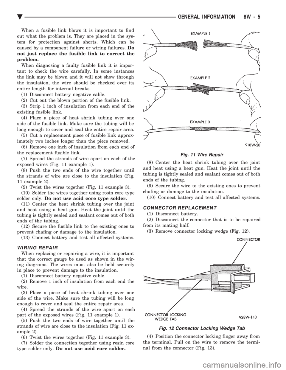
exposed wires (Fig. 11 example 1). (8) Push the two ends of the wire together until
the strands of wire are close to the insulation (Fig.
11 example 2). (9) Twist the wires together (Fig. 11 example 3).
(10) Solder the wires together using rosin core type
solder only. Do not use acid core type solder.
(11) Center the heat shrink tubing over the joint
and heat using a heat gun. Heat the joint until the
tubing is tightly sealed and sealant comes out of both
ends of the tubing. (12) Secure the fusible link to the existing ones to
prevent chafing or damage to the insulation. (13) Connect battery and test all affected systems.
WIRING REPAIR
When replacing or repairing a wire, it is important
that the correct gauge be used as shown in the wir-
ing diagrams. The wires must also be held securely
in place to prevent damage to the insulation. (1) Disconnect battery negative cable.
(2) Remove 1 inch of insulation from each end the
wire. (3) Place a piece of heat shrink tubing over one
side of the wire. Make sure the tubing will be long
enough to cover and seal the entire repair area. (4) Spread the strands of the wire apart on each
part of the exposed wires (Fig. 11 example 1). (5) Push the two ends of wire together until the
strands of wire are close to the insulation (Fig. 11 ex-
ample 2). (6) Twist the wires together (Fig. 11 example 3).
(7) Solder the connection together using rosin core
type solder only. Do not use acid core solder. (8) Center the heat shrink tubing over the joint
and heat using a heat gun. Heat the joint until the
tubing is tightly sealed and sealant comes out of both
ends of the tubing. (9) Secure the wire to the existing ones to prevent
chafing or damage to the insulation. (10) Connect battery and test all affected systems.
CONNECTOR REPLACEMENT
(1) Disconnect battery.
(2) Disconnect the connector that is to be repaired
from its mating half. (3) Remove connector locking wedge (Fig. 12).
(4) Position the connector locking finger away from
the terminal. Pull on the wire to remove the termi-
nal from the connector (Fig. 13).
Fig. 11 Wire Repair
Fig. 12 Connector Locking Wedge Tab
Ä GENERAL INFORMATION 8W - 5