1993 CHEVROLET PLYMOUTH ACCLAIM run flat
[x] Cancel search: run flatPage 63 of 2438

FRONT SUSPENSION SERVICE PROCEDURES INDEX
page page
Ball Joints .............................. 13
Hub and Bearing Assembly ................. 20
Knuckle (Front Suspension) ................. 16
Lower Control Arm ....................... 10
Lower Control Arm Pivot Bushings ........... 11 Shock Absorbers (Strut Damper)
............. 10
Strut Damper Assembly ..................... 7
Suspension Coil Springs .................... 9
Sway Bar .............................. 14
Wheel Alignment .......................... 5
WHEEL ALIGNMENT
Front wheel alignment is the proper adjustment of
all interrelated front suspension angles. These angles
are what affects the running and steering of the
front wheels of the vehicle. The method of checking front alignment will vary
depending on the type of equipment being used. The
instructions furnished by the manufacturer of the
equipment should always be followed. With the ex-
ception that the alignment specifications recom-
mended by Chrysler Corporation be used. There are six basic factors which are the founda-
tion to front wheel alignment. These are height,
caster, camber, toe-in, steering axis inclination and
toe-out on turns. Of the six basic factors only camber
and toe in are mechanically adjustable (Fig. 1)
CAUTION: Do not attempt to modify any suspen-
sion or steering components by heating or bending
of the component.
Wheel alignment adjustments and checks should be
made in the following sequence. (1) Camber
(2) Toe
Camber is the number of degrees the top of the
wheel is tilted inward or outward from true vertical.
Inward tilt is negative camber. Outward tilt is posi-
tive camber. Excessive camber is a tire wear factor: negative
camber causes wear on the inside of the tire, while
positive camber causes wear to the outside. Toe
is measured in degrees or inches and is the
distance the front edges of the tires are closer (or far-
ther apart) than the rear edges. See Front Wheel
Drive Specifications for Toesettings.
PRE-ALIGNMENT
Before any attempt is made to change or correct
the wheel alignment factors. The following inspection
and necessary corrections must be made on those
parts which influence the steering of the vehicle. (1) Check and inflate tires to recommended pres-
sure. All tires should be the same size and in good
condition and have approximately the same wear.
Note type of tread wear which will aid in diagnosing,
see Wheels and Tires, Group 22. (2) Check front wheel and tire assembly for radial
runout. (3) Inspect lower ball joints and all steering link-
age for looseness. (4) Check for broken or sagged front and rear
springs. Front suspension must only be checked after the
vehicle has had the following checked or adjusted.
Tires set to recommended pressures, full tank of fuel,
no passenger or luggage compartment load and is on
a level floor or alignment rack. Just prior to each alignment reading. The vehicle
should be bounced (rear first, then front) by grasping
bumper at center and jouncing each end an equal
number of times. Always release bumpers at bottom
of down cycle.
Ä SUSPENSION AND DRIVESHAFTS 2 - 5
Page 90 of 2438

INNER C/V JOINT
DISASSEMBLE
With driveshaft assembly removed from vehicle,
identify unit type (See Fig. 2 under Driveshafts Iden-
tification). (1) Remove the boot clamps and pull back the boot
to gain access to the tripod retention system, which
prevents accidental separation from the C/V joint
housing.
CAUTION: When removing the housing from the tri-
pod, hold the rollers in place on the trunnion studs
to prevent the rollers and needle bearings from fall-
ing away. After the tripod is out of the housing se-
cure the rollers in place with tape (Fig. 4).
(2) Depending on the type of C/V joint assembly,
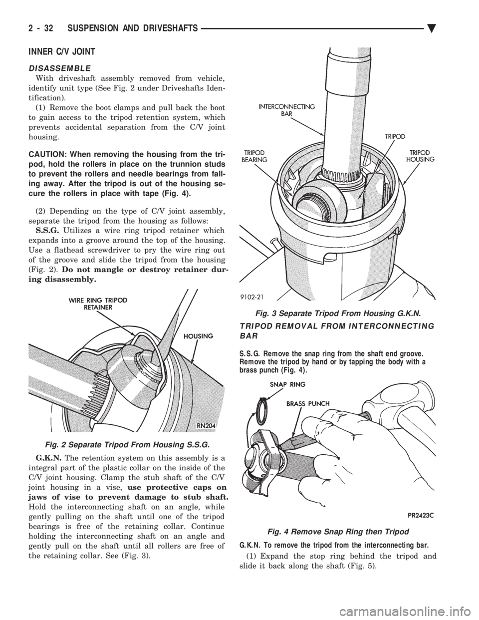
separate the tripod from the housing as follows: S.S.G. Utilizes a wire ring tripod retainer which
expands into a groove around the top of the housing.
Use a flathead screwdriver to pry the wire ring out
of the groove and slide the tripod from the housing
(Fig. 2). Do not mangle or destroy retainer dur-
ing disassembly.
G.K.N. The retention system on this assembly is a
integral part of the plastic collar on the inside of the
C/V joint housing. Clamp the stub shaft of the C/V
joint housing in a vise, use protective caps on
jaws of vise to prevent damage to stub shaft.
Hold the interconnecting shaft on an angle, while
gently pulling on the shaft until one of the tripod
bearings is free of the retaining collar. Continue
holding the interconnecting shaft on an angle and
gently pull on the shaft until all rollers are free of
the retaining collar. See (Fig. 3).
TRIPOD REMOVAL FROM INTERCONNECTING BAR
S.S.G. Remove the snap ring from the shaft end groove.
Remove the tripod by hand or by tapping the body with a
brass punch (Fig. 4).
G.K.N. To remove the tripod from the interconnecting bar.
(1) Expand the stop ring behind the tripod and
slide it back along the shaft (Fig. 5).
Fig. 2 Separate Tripod From Housing S.S.G.
Fig. 3 Separate Tripod From Housing G.K.N.
Fig. 4 Remove Snap Ring then Tripod
2 - 32 SUSPENSION AND DRIVESHAFTS Ä
Page 119 of 2438

A compression ball sleeve nut and sleeve for 3/16
inch tubing with ball sleeve connector and an inter-
nal pipe T-fitting. Can be used to attach the tubing
to the pressure gauge. (3) Cycle ignition from OFF to ON.
(4) Apply a load to the rear of the vehicle (two as-
sistants or approximately 300-325 lbs.) to run com-
pressor and raise the vehicle. (5) Remove the load applied in Step 4. Allow the
system to exhaust and lower the vehicle. (6) When no more air can be exhausted, the gauge
should indicate 69 to 152 kPa (10 to 22 psi). (7) Remove the pressure gauge and nylon tubing.
Attach the air line between the dryer and shock ab-
sorber. Repeat Steps 3, 4, and 5 to ensure system air
pressure is in the shocks.
LEAK CHECKS
(1) Repeat Residual Air Check Steps 1, 2, 3, and 4.
Allow the system to fill until gauge reads 483 to 621
kPa (70 to 90 psi). If compressor is permitted to run until it reaches
its maximum output pressure, the vent solenoid
valve will function as a relief valve. The resulting
leak down, when compressor shuts off, will indicate a
false air leak. (2) With load still applied, disconnect wire harness
connector from the control module, then remove ap-
plied load. Vehicle should rise. Cycle ignition switch
to OFF. (3) Observe if pressure leaks down or holds steady
(wait approximately 15 minutes). (A) If system will not inflate beyond 345 kPa (50
psi). A severe leak may be indicated. Check for a
pinched pressure line between compressor and
shocks. (B) The standard soap solution check procedure is
acceptable. (C) If pressure holds steady, perform the diagnosis
procedures.
SYSTEM OPERATION
RAISING VEHICLE HEIGHT
When weight is added to the rear suspension. The
body of the vehicle is lowered, moving the height
sensor down. This action will activate the internal time delay
circuit. After a time delay of 12 to 18 seconds. The
control module (CM) activates the ground circuit to
the compressor relay. With the relay energized, the compressor motor
runs and air is sent through the system. As the
shock absorbers inflate, the body moves upward to a
corrected position. When the body reaches the correct
height, the control module (CM) stops the compressor
operation.
LOWERING VEHICLE HEIGHT
When the weight is removed from the vehicle. The
body moves upward, which allows the height sensor
to move upward and activate the internal time delay
circuit. After a time delay of 12 to 18 seconds. The (CM)
activates the exhaust solenoid circuit. Air is ex-
hausted from the shock absorbers through the air
dryer and exhaust solenoid to the atmosphere. As the body lowers, the height sensor is lowered to-
ward its original position. When the body reaches the
original vehicle height, the (CM) opens the exhaust
solenoid valve circuit.
COMPRESSOR PERFORMANCE TEST
This test can be performed on the vehicle. It is
used to evaluate compressor current draw, pressure
output, and leak down. (1) Disconnect the compressor motor wiring har-
ness connector. (2) Disconnect air line between dryer and right
shock absorber. (3) Connect an air pressure gauge into the system
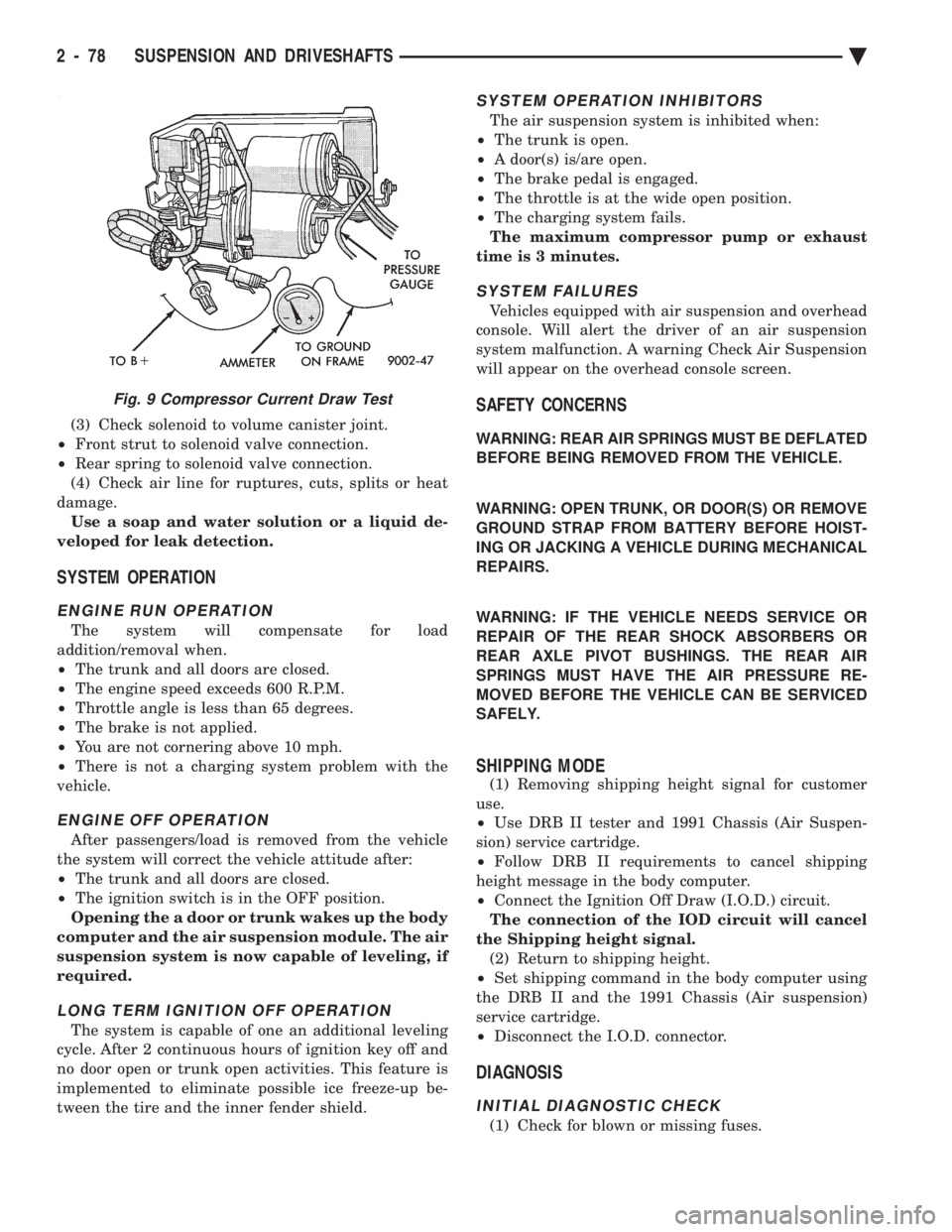
(Fig. 5). (4) Connect an ammeter in series between the red
wire terminal on compressor connector and a 12 volt
power source. Also, connect a ground wire from the
black wire terminal on the compressor connector to a
good ground on the frame (Fig. 6). (5) If the current draw to the compressor motor ex-
ceeds 21 amperes, replace the compressor assembly. (6) When the air pressure stabilizes at 827 kPa
(120 psi), disconnect the (+) wire lead from the con-
nector. Replace the compressor assembly if any of the
following conditions exists:
Fig. 5 Pressure Gauge Installed in System
Ä SUSPENSION AND DRIVESHAFTS 2 - 61
Page 136 of 2438

(3) Check solenoid to volume canister joint.
² Front strut to solenoid valve connection.
² Rear spring to solenoid valve connection.
(4) Check air line for ruptures, cuts, splits or heat
damage. Use a soap and water solution or a liquid de-
veloped for leak detection.
SYSTEM OPERATION
ENGINE RUN OPERATION
The system will compensate for load
addition/removal when.
² The trunk and all doors are closed.
² The engine speed exceeds 600 R.P.M.
² Throttle angle is less than 65 degrees.
² The brake is not applied.
² You are not cornering above 10 mph.
² There is not a charging system problem with the
vehicle.
ENGINE OFF OPERATION
After passengers/load is removed from the vehicle
the system will correct the vehicle attitude after:
² The trunk and all doors are closed.
² The ignition switch is in the OFF position.
Opening the a door or trunk wakes up the body
computer and the air suspension module. The air
suspension system is now capable of leveling, if
required.
LONG TERM IGNITION OFF OPERATION
The system is capable of one an additional leveling
cycle. After 2 continuous hours of ignition key off and
no door open or trunk open activities. This feature is
implemented to eliminate possible ice freeze-up be-
tween the tire and the inner fender shield.
SYSTEM OPERATION INHIBITORS
The air suspension system is inhibited when:
² The trunk is open.
² A door(s) is/are open.
² The brake pedal is engaged.
² The throttle is at the wide open position.
² The charging system fails.
The maximum compressor pump or exhaust
time is 3 minutes.
SYSTEM FAILURES
Vehicles equipped with air suspension and overhead
console. Will alert the driver of an air suspension
system malfunction. A warning Check Air Suspension
will appear on the overhead console screen.
SAFETY CONCERNS
WARNING: REAR AIR SPRINGS MUST BE DEFLATED
BEFORE BEING REMOVED FROM THE VEHICLE.
WARNING: OPEN TRUNK, OR DOOR(S) OR REMOVE
GROUND STRAP FROM BATTERY BEFORE HOIST-
ING OR JACKING A VEHICLE DURING MECHANICAL
REPAIRS.
WARNING: IF THE VEHICLE NEEDS SERVICE OR
REPAIR OF THE REAR SHOCK ABSORBERS OR
REAR AXLE PIVOT BUSHINGS. THE REAR AIR
SPRINGS MUST HAVE THE AIR PRESSURE RE-
MOVED BEFORE THE VEHICLE CAN BE SERVICED
SAFELY.
SHIPPING MODE
(1) Removing shipping height signal for customer
use.
² Use DRB II tester and 1991 Chassis (Air Suspen-
sion) service cartridge.
² Follow DRB II requirements to cancel shipping
height message in the body computer.
² Connect the Ignition Off Draw (I.O.D.) circuit.
The connection of the IOD circuit will cancel
the Shipping height signal. (2) Return to shipping height.
² Set shipping command in the body computer using
the DRB II and the 1991 Chassis (Air suspension)
service cartridge.
² Disconnect the I.O.D. connector.
DIAGNOSIS
INITIAL DIAGNOSTIC CHECK
(1) Check for blown or missing fuses.
Fig. 9 Compressor Current Draw Test
2 - 78 SUSPENSION AND DRIVESHAFTS Ä
Page 203 of 2438

BRAKE DISC (ROTOR) INDEX
page page
Braking Disc Removal ..................... 54
General Information ....................... 53
Inspection Diagnosis ...................... 53 Installing Braking Disc
..................... 54
Refinishing Braking Disc ................... 55
Service Procedures ....................... 53
GENERAL INFORMATION
Any servicing of the braking disc requires extreme
care to maintain the braking disc within service toler-
ances to ensure proper brake action.
CAUTION: If the braking disk (rotor) needs to be
replaced with a new part. The protective coating on
the braking surfaces of the rotor MUST BE REMOVED
with an appropriate solvent, to avoid contamination
of the brake shoe linings.
When replacing a rotor with a new part do NOT
reface the new rotor. Rotor already has the re-
quired micro finish when manufactured, only
remove the protective coating.
INSPECTION DIAGNOSIS
Before refinishing or refacing a braking disc, the disc
should be checked and inspected for the following
conditions: Braking surface scoring, rust, impregnation of lining
material and worn ridges. Excessive lateral rotor runout or wobble.
Thickness variation (Parallelism).
Dishing or distortion (Flatness).
If a vehicle has not been driven for a period of time.
The discs will rust in the area not covered by the brake
lining and cause noise and chatter when the brakes are
applied. Excessive wear and scoring of the disc can cause
temporary improper lining contact if ridges are not
removed before installation of new brake shoe assem-
blies. Some discoloration or wear of the disc surface is
normal and does not require resurfacing when linings
are replaced. Excessive runout or wobble in a disc can increase
pedal travel due to piston knock back. This will in-
crease guide pin bushing wear due to tendency of
caliper to follow disc wobble. Thickness variation in a disc can also result in pedal
pulsation, chatter and surge due to variation in brake
output. This can also be caused by excessive runout in
braking disc or hub. Dishing or distortion can be caused by extreme heat
and abuse of the brakes.
SERVICE PROCEDURES
CHECKING BRAKING DISC FOR RUNOUT AND THICKNESS
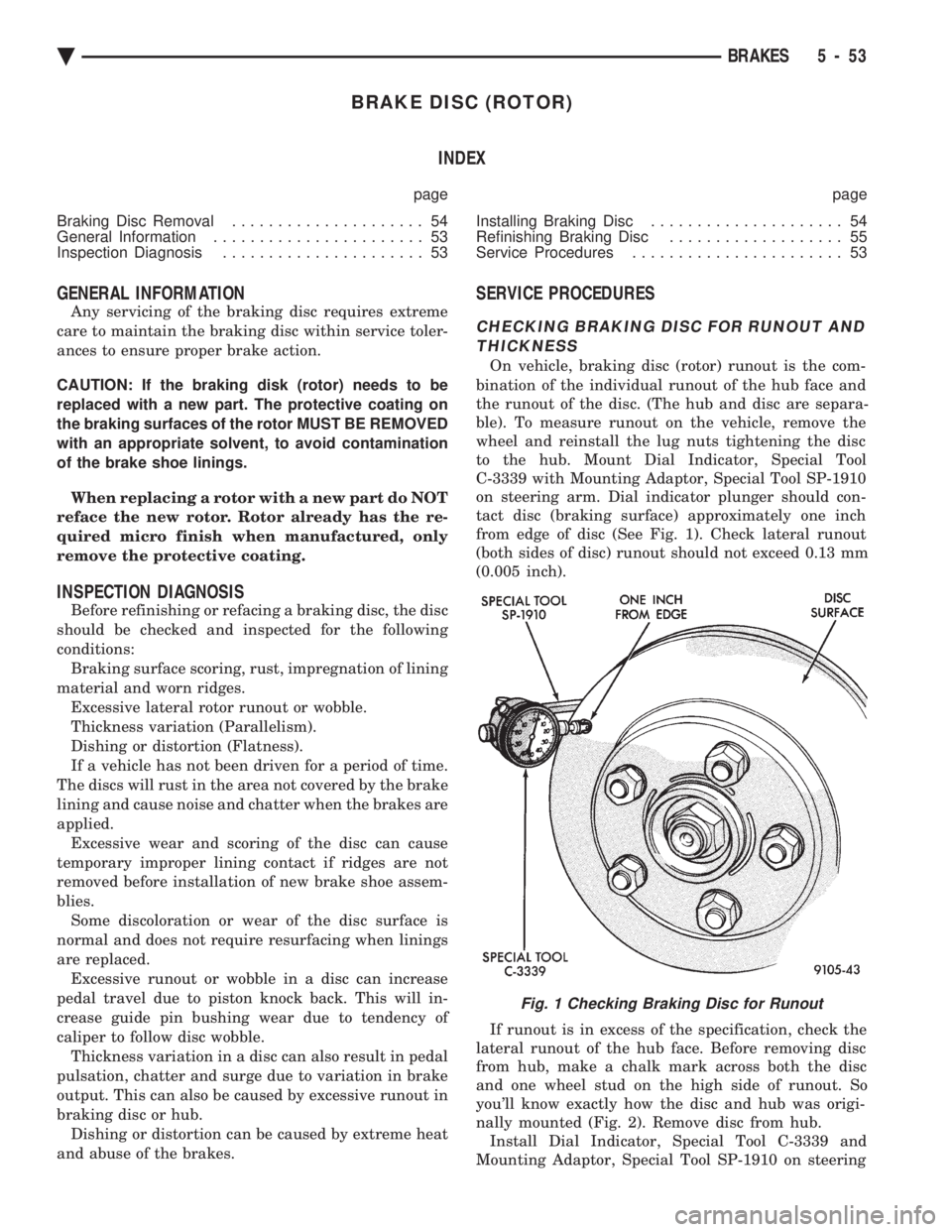
On vehicle, braking disc (rotor) runout is the com-
bination of the individual runout of the hub face and
the runout of the disc. (The hub and disc are separa-
ble). To measure runout on the vehicle, remove the
wheel and reinstall the lug nuts tightening the disc
to the hub. Mount Dial Indicator, Special Tool
C-3339 with Mounting Adaptor, Special Tool SP-1910
on steering arm. Dial indicator plunger should con-
tact disc (braking surface) approximately one inch
from edge of disc (See Fig. 1). Check lateral runout
(both sides of disc) runout should not exceed 0.13 mm
(0.005 inch).
If runout is in excess of the specification, check the
lateral runout of the hub face. Before removing disc
from hub, make a chalk mark across both the disc
and one wheel stud on the high side of runout. So
you'll know exactly how the disc and hub was origi-
nally mounted (Fig. 2). Remove disc from hub. Install Dial Indicator, Special Tool C-3339 and
Mounting Adaptor, Special Tool SP-1910 on steering
Fig. 1 Checking Braking Disc for Runout
Ä BRAKES 5 - 53
Page 230 of 2438

stant velocity joint housings. The rear Tone Wheels
are serviced as an assembly with the rear disc brake
rotor hub. Correct Anti-Lock System operation is dependent
on wheel speed signals from the wheel speed sensors.
The vehicles' wheels and tires must all be the same
size and type to generate accurate signals. In addi-
tion, the tires must be inflated to the recommended
pressures for optimum system operation. Variations
in wheel and tire size or significant variations in in-
flation pressure can produce inaccurate wheel speed
signals.
CONTROLLER ANTI-LOCK BRAKE (CAB)
The Anti-Lock Brake Controller is a small micro-
processor based device that monitors the brake sys- tem and controls the system while it functions in
Anti-Lock Mode. The CAB is located under the bat-
tery tray and is mounted to the left frame rail (Fig.
7) and uses a 60-way system connector. The power
source for the CAB is through the ignition switch to
pin 60 of the controller. With the ignition in the
RUN or ON position. IF THE (ABS) CONTROL-
LER NEEDS TO BE REPLACED BE SURE THE
CORRECT CONTROLLER IS USED. THE CON-
TROLLER ANTI-LOCK BRAKE (CAB) IS NOT
ON THE CCD BUS
Fig. 5 Rear Wheel Speed Sensor
Fig. 4 Front Wheel Speed Sensor
Fig. 6 Rear Tone Wheel
Fig. 7 Location Controller Anti-Lock Brake (CAB)
5 - 80 ANTI-LOCK 10 BRAKE SYSTEM Ä
Page 304 of 2438

WHEEL SPEED SENSORS
One Wheel Speed Sensor (WSS), is located at each
wheel (Fig. 5 and 6), and sends a small AC signal to the
control module CAB. This signal is generated by mag-
netic induction. The magnetic induction is created,
when a toothed sensor ring (Tone Wheel) (Fig. 7) passes
a stationary magnetic Wheel Speed Sensor. The CAB
converts the AC signal generated at each wheel into a
digital signal. If a wheel locking tendency is detected,
the CAB will then modulate hydraulic pressure to pre-
vent the wheel or wheels from locking.
The front Wheel Speed Sensor is attached to a boss
in the steering knuckle (Fig. 5). The tone wheel is
part of the outboard constant velocity joint (Fig. 5). The rear Wheel Speed Sensor is mounted to the cal-
iper adapter (Fig. 6) and the rear tone wheel is an
integral part of the rear wheel hub (Fig. 7). The
speed sensor air gap is NOT adjustable.
The four Wheel Speed Sensors are serviced individ-
ually. The front Tone Wheels are serviced as an as-
sembly with the outboard constant velocity joint. The
rear Tone Wheels are serviced as an assembly with
the rear brake hub. Correct Antilock system operation is dependent on
the vehicle's wheel speed signals, that are generated
by the Wheel Speed Sensors. The vehicle's wheels
and tires must all be the same size and type to gen-
erate accurate signals. In addition, the tires must be
inflated to the recommended pressures for optimum
system operation. Variations in wheel and tire size
or significant variations in inflation pressure can
produce inaccurate wheel speed signals.
CONTROLLER ANTILOCK BRAKE CAB
The Antilock Brake Controller is a small micropro-
cessor based device which monitors the brake system
and controls the system while it functions in the An-
tilock mode. The CAB is mounted on the top of the
right front frame rail and uses a 60-way system con-
nector (Fig. 8). The power source for the CAB is
through the ignition switch in the Run or On posi-
tion. THE CONTROLLER ANTILOCK BRAKE
CAB IS NOT ON THE CCD BUS The primary functions of the CAB are:
(1) Detect wheel locking tendencies.
(2) Control fluid modulation to the brakes while in
Antilock mode. (3) Monitor the system for proper operation.
Fig. 5 Front Wheel Speed Sensor
Fig. 6 Rear Wheel Speed Sensor
Fig. 7 Rear Tone Wheel (Typical)
5 - 18 ANTILOCK 4 BRAKE SYSTEM Ä
Page 445 of 2438

When testing secondary cables for punctures and
cracks with an oscilloscope follow the equipment
manufacturers instructions. If an oscilloscope is not available, secondary cables
can be tested as follows:
CAUTION: Do not leave any one spark plug cable
disconnected any longer than necessary during test-
ing. Excessive heat could damage the catalytic con-
verter. Total test time must not exceed ten minutes.
(a) With the engine not running, connect one end
of a test probe to a good ground. Use a probe made of
insulated wire with insulated alligator clips on each
end. (b) With engine running, move test probe along
entire length of all cables (approximately 0 to 1/8
inch gap). If punctures or cracks are present there
will be a noticeable spark jump from the faulty area
to the probe. Check the coil cable the same way.
Replace cracked, leaking or faulty cables.
When replacing cables, install the new high
tension cable and nipple assembly over cap or
coil tower. When entering the terminal into the
tower, push lightly, then pinch the large diam-
eter of nipple to release air trapped between the
nipple and tower. Continue pushing on the cable
and nipple until cables are properly seated in the
cap towers. A snap should be heard as terminal
goes into place. Use the same procedure to install cable in coil tower.
Wipe the spark plug insulator clean before reinstalling
cable and cover. Use the following procedure when removing the high
tension cable from the spark plug. First, remove the
cable from the retaining bracket. Then grasp the ter-
minal as close as possible to the spark plug. Rotate the
cover and pull the cable straight back. Pulling on the
cable itself will damage the conductor and termi-
nal connection. Do not use pliers and do not pull
the cable at an angle. Doing so will damage the
insulation, cable terminal or the spark plug in-
sulator. Wipe spark plug insulator clean before
reinstalling cable and cover. Resistance type cable is identified by the words
Electronic Suppression printed on the cable jacket.
Use an ohmmeter to check resistance type cable for
open circuits, loose terminals or high resistance as
follows: (a) Remove cable from spark plug.
(b) Lift distributor cap from distributor with
cables intact. Do not remove cables from cap. The
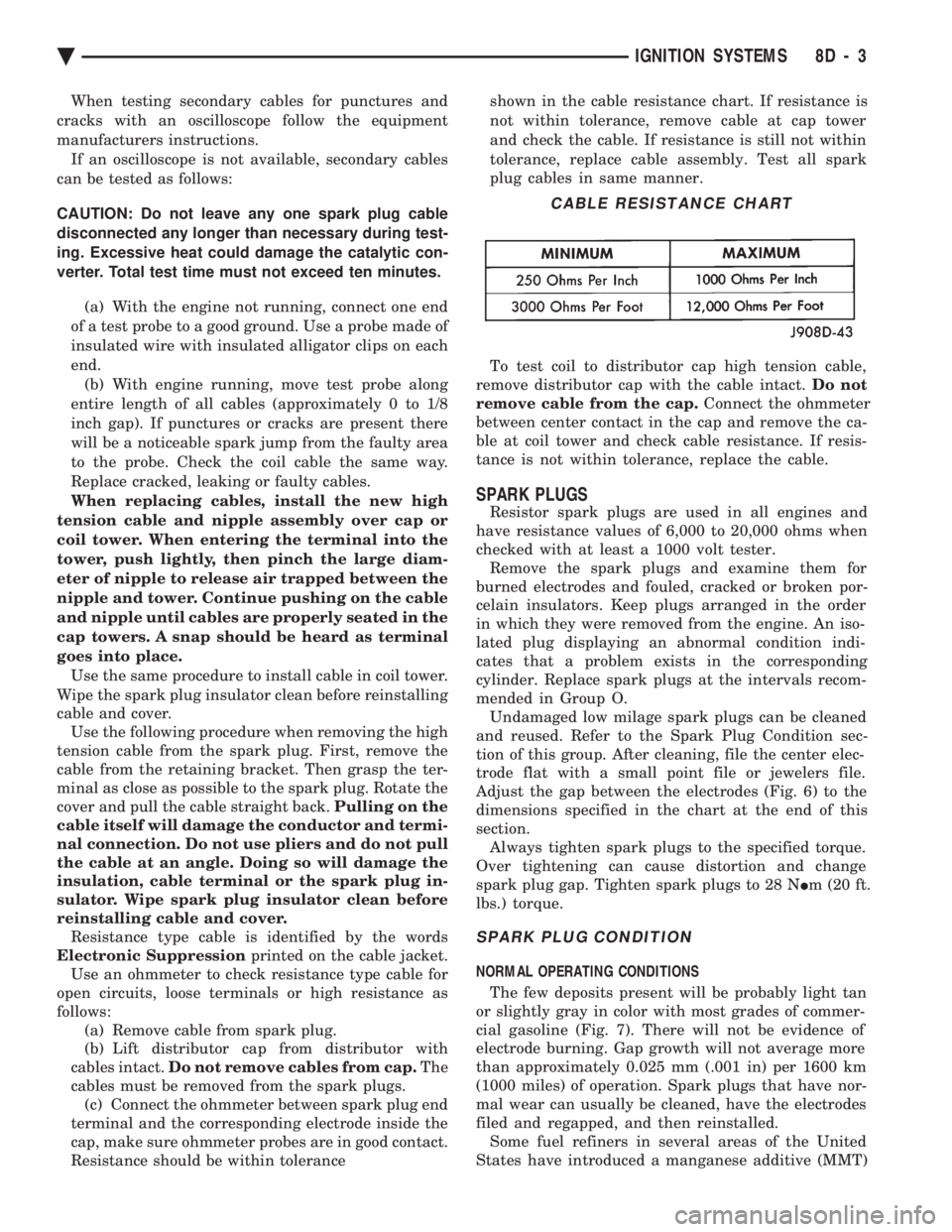
cables must be removed from the spark plugs. (c) Connect the ohmmeter between spark plug end
terminal and the corresponding electrode inside the
cap, make sure ohmmeter probes are in good contact.
Resistance should be within tolerance shown in the cable resistance chart. If resistance is
not within tolerance, remove cable at cap tower
and check the cable. If resistance is still not within
tolerance, replace cable assembly. Test all spark
plug cables in same manner.
To test coil to distributor cap high tension cable,
remove distributor cap with the cable intact. Do not
remove cable from the cap. Connect the ohmmeter
between center contact in the cap and remove the ca-
ble at coil tower and check cable resistance. If resis-
tance is not within tolerance, replace the cable.
SPARK PLUGS
Resistor spark plugs are used in all engines and
have resistance values of 6,000 to 20,000 ohms when
checked with at least a 1000 volt tester. Remove the spark plugs and examine them for
burned electrodes and fouled, cracked or broken por-
celain insulators. Keep plugs arranged in the order
in which they were removed from the engine. An iso-
lated plug displaying an abnormal condition indi-
cates that a problem exists in the corresponding
cylinder. Replace spark plugs at the intervals recom-
mended in Group O. Undamaged low milage spark plugs can be cleaned
and reused. Refer to the Spark Plug Condition sec-
tion of this group. After cleaning, file the center elec-
trode flat with a small point file or jewelers file.
Adjust the gap between the electrodes (Fig. 6) to the
dimensions specified in the chart at the end of this
section. Always tighten spark plugs to the specified torque.
Over tightening can cause distortion and change
spark plug gap. Tighten spark plugs to 28 N Im (20 ft.
lbs.) torque.
SPARK PLUG CONDITION
NORMAL OPERATING CONDITIONS
The few deposits present will be probably light tan
or slightly gray in color with most grades of commer-
cial gasoline (Fig. 7). There will not be evidence of
electrode burning. Gap growth will not average more
than approximately 0.025 mm (.001 in) per 1600 km
(1000 miles) of operation. Spark plugs that have nor-
mal wear can usually be cleaned, have the electrodes
filed and regapped, and then reinstalled. Some fuel refiners in several areas of the United
States have introduced a manganese additive (MMT)
CABLE RESISTANCE CHART
Ä IGNITION SYSTEMS 8D - 3