1993 CHEVROLET PLYMOUTH ACCLAIM jump start terminals
[x] Cancel search: jump start terminalsPage 383 of 2438

STARTER TEST PROCEDURES ON VEHICLE INDEX
page page
Diagnostic Preparation ..................... 11
General Information ....................... 11 Starter Control Circuit Tests
................ 15
Starter Feed Circuit Tests .................. 11
GENERAL INFORMATION
The starting system (Fig. 1) has:
² Ignition switch
² Starter relay (Fig. 2)
² Neutral starting and back-up switch with auto-
matic transmissions
² Clutch pedal mounted starter interlock switch
with manual transmissions
² Wiring harness
² Battery
² Starter motor with an integral solenoid
These components form two separate circuits. A
high amperage circuit that feeds the starter motor up
to 300+ amps, and a control circuit that operates on
less than 20 amps.
DIAGNOSTIC PREPARATION
Before going on with starting system diagnostics,
verify: (1) The battery top, posts, and terminals are clean.
(2) The generator drive belt tension and condition
is correct. (3) The battery state-of-charge is correct.
(4) The battery will pass load test.
(5) The battery cable connections at the starter
and engine block are clean and free from corrosion. (6) The wiring harness connectors and terminals
are clean and free from corrosion. (7) Proper circuit grounding.
(8) Refer to Starter System Diagnostics (Fig. 3).
STARTER FEED CIRCUIT TESTS
The following procedure will require a suitable
volt/ampere tester (Fig. 4).
CAUTION: Ignition system also must be disabled to
prevent engine start while performing the following
tests.
(1) Connect a volt-ampere tester (Fig. 4) to the bat-
tery terminals (Fig. 5). Refer to the operating in-
structions provided with the tester being used. (2) Disable ignition system as follows:
² VEHICLES WITH CONVENTIONAL DISTRIBU-
TORS: Disconnect the ignition coil cable from the
distributor cap. Connect a suitable jumper wire be-
tween the coil cable end-terminal and a good body
ground (Fig. 6).
Fig. 1 Starting Components/Wiring
Fig. 2 Starter Relay
Ä BATTERY/STARTING/CHARGING SYSTEMS DIAGNOSTICS 8A - 11
Page 393 of 2438
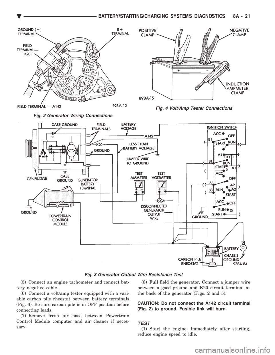
(5) Connect an engine tachometer and connect bat-
tery negative cable. (6) Connect a volt/amp tester equipped with a vari-
able carbon pile rheostat between battery terminals
(Fig. 6). Be sure carbon pile is in OFF position before
connecting leads. (7) Remove fresh air hose between Powertrain
Control Module computer and air cleaner if neces-
sary. (8) Full field the generator. Connect a jumper wire
between a good ground and K20 circuit terminal at
the back of the generator (Figs. 2 and 5).
CAUTION: Do not connect the A142 circuit terminal
(Fig. 2) to ground. Fusible link will burn.
TEST
(1) Start the engine. Immediately after starting,
reduce engine speed to idle.
Fig. 2 Generator Wiring Connections
Fig. 3 Generator Output Wire Resistance Test
Fig. 4 Volt/Amp Tester Connections
Ä BATTERY/STARTING/CHARGING SYSTEMS DIAGNOSTICS 8A - 21
Page 454 of 2438
make sure that the spark plugs are firing. Inspect the
distributor rotor, cap, spark plug cables, and spark
plugs. If they are in proper working order, the ignition
system is not the reason why the engine will not start.
Inspect the fuel system and engine for proper opera-
tion.
FAILURE TO START TESTÐ2.5L TBI AND 3.0L
ENGINES
Before proceeding with this test make sure
Testing For Spark At Coil has been performed.
Failure to do this may lead to unnecessary diag-
nostic time and wrong test results.
WARNING: BE SURE TO APPLY PARKING BRAKE
AND/OR BLOCK WHEELS BEFORE PERFORMING
ANY TEST WITH THE ENGINE RUNNING.
(1) Battery voltage must be at least 12.4 volts to
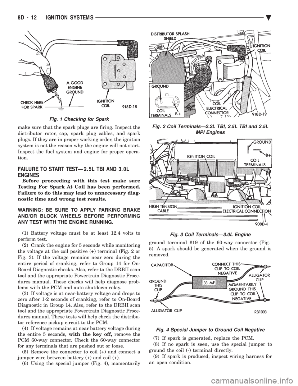
perform test. (2) Crank the engine for 5 seconds while monitoring
the voltage at the coil positive (+) terminal (Fig. 2 or
Fig. 3). If the voltage remains near zero during the
entire period of cranking, refer to Group 14 for On-
Board Diagnostic checks. Also, refer to the DRBII scan
tool and the appropriate Powertrain Diagnostic Proce-
dures manual. These checks will help diagnose prob-
lems with the PCM and auto shutdown relay. (3) If voltage is at near-battery voltage and drops to
zero after 1-2 seconds of cranking, refer to On-Board
Diagnostic in Group 14. Also, refer to the DRBII scan
tool and the appropriate Powertrain Diagnostic Proce-
dures manual. These tests will help check the distribu-
tor reference pickup circuit to the PCM. (4) If voltage remains at near battery voltage during
the entire 5 seconds, with the key off,remove the
PCM 60-way connector. Check the 60-way connector
for any terminals that are pushed out or loose. (5) Remove the connector to coil (+) and connect a
jumper wire between battery (+) and coil (+). (6) Using the special jumper (Fig. 4), momentarily ground terminal #19 of the 60-way connector (Fig.
5). A spark should be generated when the ground is
removed.
(7) If spark is generated, replace the PCM.
(8) If no spark is seen, use the special jumper to
ground the coil (-) terminal directly. (9) If spark is produced, inspect wiring harness for
an open condition.
Fig. 2 Coil TerminalsÐ2.2L TBI, 2.5L TBI and 2.5L MPI Engines
Fig. 3 Coil TerminalsÐ3.0L Engine
Fig. 4 Special Jumper to Ground Coil Negative
Fig. 1 Checking for Spark
8D - 12 IGNITION SYSTEMS Ä
Page 483 of 2438

(2) With engine running, move test probe along
entire length of all cables (approximately 0 to 1/8
inch gap). If punctures or cracks are present there
will be a noticeable spark jump from the faulty area
to the probe. Cracked, leaking or faulty cables should
be replaced. Use the following procedure when removing the
high tension cable from the spark plug. First, remove
the cable from the retaining bracket. Then grasp the
terminal as close as possible to the spark plug. Ro-
tate the cover (boot) slightly and pull straight back.
Do not use pliers and do not pull the cable at an
angle. Doing so will damage the insulation, cable
terminal or the spark plug insulator. Wipe spark
plug insulator clean before reinstalling cable
and cover. Resistance cables are identified by the words Elec-
tronic Suppression .
Use an ohmmeter to check cables for opens, loose
terminals or high resistance. (a) Remove cable from spark plug.
(b) Remove cable from the coil tower.
(c) Connect the ohmmeter between spark plug
end terminal and the coil end terminal. Resistance
should be within tolerance shown in the cable re-
sistance chart. If resistance is not within tolerance,
replace cable assembly. Test all spark plug cables
in same manner.
SPARK PLUG SERVICE
When replacing the spark plug cables, route the ca-
bles correctly and secure them in the appropriate re-
tainers. Incorrectly routed cables can cause the radio
to reproduce ignition noise. It can also cause cross ig-
nition of the spark plugs or short circuit the cables to
ground.
SPARK PLUG REMOVAL
Always remove cables by grasping at boot, rotating
the boot 1/2 turn, and pulling straight back in a
steady motion. (1) Prior to removing the spark plug spray com-
pressed air around the spark plug hole and the area
around the spark plug. (2) Remove the spark plug using a quality socket
with a rubber or foam insert. (3) Inspect the spark plug condition. Refer to
Spark Plug Condition in this section.
SPARK PLUG GAP ADJUSTMENT
Check the spark plug gap with a gap gauge. If the
gap is not correct, adjust it by bending the ground
electrode (Fig. 6).
SPARK PLUG INSTALLATION
(1) To avoid cross threading, start the spark plug
into the cylinder head by hand. (2) Tighten spark plugs to 28 N Im (20 ft. lbs.)
torque. (3) Install spark plug cables over spark plugs.
IDLE RPM TEST
WARNING: BE SURE TO APPLY PARKING BRAKE
AND/OR BLOCK WHEELS BEFORE PERFORMING
ANY ENGINE RUNNING TESTS.
Engine idle set rpmshould be tested and recorded
as it is when the vehicle is first brought into shop
for testing. This will assist in diagnosing complaints
of engine stalling, creeping and hard shifting on ve-
hicles equipped with automatic transaxle. Refer to the
Throttle Body Minimum Airflow procedures in Group
14.
IGNITION TIMING PROCEDURE
Ignition timing cannot be changed or set on Turbo
III, 3.3L or 3.8L engines. For diagnostic information,
refer to the DRBII scan tool and the appropriate
Powertrain Diagnostics Procedures manual.
CABLE RESISTANCE CHART
Fig. 6 Setting Spark Plug GapÐTypical
Ä IGNITION SYSTEMS 8D - 41
Page 2315 of 2438
(1) Attach manifold gauge set.
(2) Open the windows of the passenger compart-
ment and set the air conditioning controls to A/C,
RECIRC, and Low blower speed. (3) Start the engine and allow it to warm up to
normal running temperature. (4) If the air conditioning compressor does not en-
gage, disconnect the low pressure cut-off switch.
Place a jumper wire across the terminals in the con-
nector boot. If the compressor still does not engage, a
problem exists in the compressor clutch feed circuit. (6) Hold the engine speed at 1400 rpm.
(7) Following the instructions provided with the
charging equipment being used. Charge through the
suction side of the system. Use enough refrigerant to
clear the sight glass in the filter drier. (8) At the point when the sight glass clears, note
the weight of the refrigerant supply drum or the
level in the charging cylinder. Then add an addi-
tional 340 g (12 oz) of refrigerant to the system. Re- move the jumper wire from the low pressure cut-off
switch connector and connect the cut-off switch.
(9) Test the over all performance of the air condi-
tioner as described in A/C Overall Performance Test
in this Group. Close all valves on the charging equip-
ment and disconnect the hoses from the service ports
as described in the Manifold Gauge Set Connections
section of this Group. Install the service port caps.
DISCHARGING REFRIGERANT SYSTEM
(R-12) refrigerant is a chlorofluorocarbon (CFC)
that can contribute to the depletion of the ozone
layer in the upper atmosphere. To help protect the
ozone layer, an R-12 refrigerant recycling device
must be used. Use this device when it is necessary to
empty the refrigerant system. Contact an automotive
service equipment supplier for refrigerant recycling
equipment. Refer to the operating instructions pro-
vided with the recycling equipment for proper opera-
tion.
EVACUATING REFRIGERANT SYSTEM
If the A/C system has been open to the atmosphere,
it must be evacuated before the system can be
charged. Moisture and air mixed with the refrigerant
will raise the compressor head pressure above accept-
able operating levels. This will reduce the perfor-
mance of the air conditioner and damage the
compressor. Moisture will boil at near room temper-
ature when exposed to vacuum. To evacuate the re-
frigerant system: (1) Connect a suitable charging station, refrigerant
recovery machine, and a manifold gauge set with
vacuum pump. (2) Open the suction and discharge valves and
start the vacuum pump. When the suction gauge
reads -88 kPa (-26 in. Hg) vacuum or greater, close
all valves and turn off vacuum pump. If the system
fails to reach specified vacuum, the refrigerant sys-
tem likely has a leak that must be corrected. If the
refrigerant system maintains specified vacuum for at
least 30 minutes, start the vacuum pump. Then open
the suction and discharge valves, and allow the sys-
tem to evacuate an additional 10 minutes. (3) Close all valves. Turn off and disconnect the
vacuum pump. The refrigerant system is prepared to be charged
with refrigerant.
CHARGING REFRIGERANT SYSTEMÐEMPTY
SYSTEM
CAUTION: Do not over charge refrigerant system,
as excessive compressor head pressure can cause
noise and system failure.
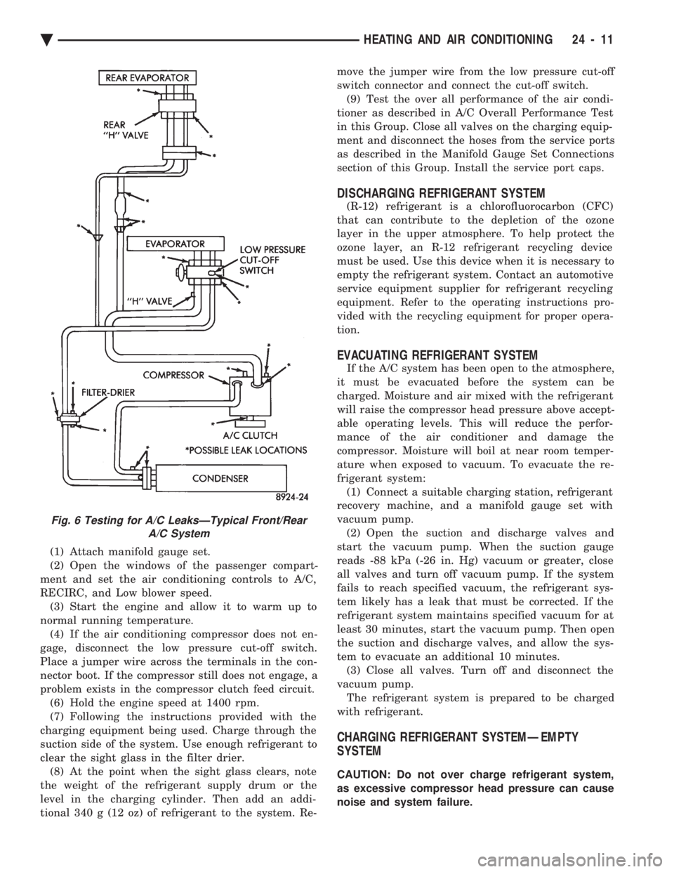
Fig. 6 Testing for A/C LeaksÐTypical Front/Rear A/C System
Ä HEATING AND AIR CONDITIONING 24 - 11
Page 2352 of 2438
WARNING: AVOID RADIATOR/CONDENSER FAN
BLADES WHEN WORKING IN THE RADIATOR
AREA. FAN IS CONTROLLED BY TEMPERATURE
AND CAN START ANY TIME IGNITION IS ON. PER-
SONAL INJURY CAN RESULT.
(1) Disconnect fan control switch wire connector.
(2) Using a suitable jumper wire, jump across ter-
minals in wire connector. (3) Connect a suitable continuity tester across fan
control switch terminals. (4) Start engine and set idle at 1300 rpm. The ra-
diator fan should run constantly. (5) Set the A/C controls to A/C and high blower.
(6) If the high pressure gauge reads below 1102
kPa (160 psi) there should be no continuity across
the switch terminals.
CAUTION: Do not allow engine to overheat when ra-
diator air flow is blocked.
(7) Block radiator air flow with a suitable cover to
increase the high side pressure to at least 1585 kPa
(230 psi). Electrical continuity should be detected
across the fan control switch terminals. (8) Remove cover from front of vehicle to allow
high side pressure to decrease. When pressure drops
below 1102 kPa (160 psi), continuity should cease. If fan control switch is defective, replace it.
REMOVAL AND INSTALLATION
CAUTION: Refrigerant removal is not necessary
when removing the Condenser Fan Control Switch.
However, a small amount of refrigerant will vent
from the switch port. Review the refrigerant han-
dling section of Safety Precautions and Warnings in
the General Information section of this Group.
(1) Disconnect wire connector from condenser fan
control switch. (2) Loosen and quickly rotate the switch counter-
clockwise and separate from the high pressure line
switch port. To install, reverse the preceding operation.
DIFFERENTIAL PRESSURE CUT-OUT SWITCH
DIAGNOSIS
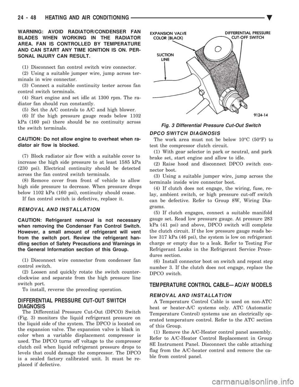
The Differential Pressure Cut-Out (DPCO) Switch
(Fig. 3) monitors the liquid refrigerant pressure on
the liquid side of the system. The DPCO is located on
the expansion valve. The expansion valve is black in
color when a variable displacement compressor is
used. The DPCO turns off voltage to the compressor
clutch coil when liquid refrigerant pressure drops to
levels that could damage the compressor. The DPCO
is a sealed factory calibrated unit. It must be re-
placed if defective.
DPCO SWITCH DIAGNOSIS
The work area must not be below 10ÉC (50ÉF) to
test the compressor clutch circuit. (1) With gear selector in park or neutral, and park
brake set, start engine and allow to idle. (2) Raise hood and disconnect DPCO switch con-
nector boot. (3) Using a suitable jumper wire, jump across the
terminals inside wire connector boot. (4) If clutch does not engage, the wiring, fuse, re-
lay, ambient switch, or high pressure cut-off switch
can be defective. Refer to Group 8W, Wiring Dia-
grams. (5) If clutch engages, connect a suitable manifold
gauge set. Read low pressure gauge. At pressure 283
kPa (41 psi) and above, DPCO switch will complete
the clutch circuit. If the low pressure gauge reads be-
low 317 kPa (46 psi), the system is low on refrigerant
charge or empty due to a leak. Refer to Testing For
Refrigerant Leaks in the Refrigerant Service Proce-
dures section. (6) Install connector boot on switch and repeat step
number 3. If the clutch does not engage, replace the
DPCO switch.
TEMPERATURE CONTROL CABLEÐAC/AY MODELS
REMOVAL AND INSTALLATION
A Temperature Control Cable is used on non-ATC
heat or heater-A/C systems only. ATC (Automatic
Temperature Control) systems use an electrically op-
erated temperature control. Refer to the ATC section
of this Group. (1) Remove the A/C-Heater control panel assembly.
Refer to A/C-Heater Control Replacement in Group
8E Instrument Panel. Disconnect the cable attaching
flag from the A/C-heater control and remove the ca-
ble from control panel.
Fig. 3 Differential Pressure Cut-Out Switch
24 - 48 HEATING AND AIR CONDITIONING Ä
Page 2358 of 2438
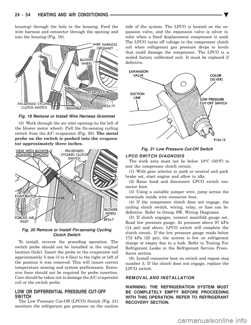
housing) through the hole in the housing. Feed the
wire harness and connector through the opening and
into the housing (Fig. 19). (3) Work through the air inlet opening (to the left of
the blower motor wheel). Pull the fin-sensing cycling
switch from the A/C evaporator (Fig. 20). The metal
probe on the switch is pushed into the evapora-
tor approximately three inches.
To install, reverse the preceding operation. The
switch probe should not be installed in the original
location (hole). Insert the probe in the evaporator coil
approximately 5 mm (3 to 4 fins) to the right or left of
the position it was removed. This will insure correct
temperature sensing and system performance. Exces-
sive force should not be required for probe insertion.
Care should be taken not to damage the A/C evaporator
coil or the switch probe.
LOW OR DIFFERENTIAL PRESSURE CUT-OFF
SWITCH
The Low Pressure Cut-Off (LPCO) Switch (Fig. 21)
monitors the refrigerant gas pressure on the suction side of the system. The LPCO is located on the ex-
pansion valve, and the expansion valve is silver in
color when a fixed displacement compressor is used.
The LPCO turns off voltage to the compressor clutch
coil when refrigerant gas pressure drops to levels
that could damage the compressor. The LPCO is a
sealed factory calibrated unit. It must be replaced if
defective.
LPCO SWITCH DIAGNOSIS
The work area must not be below 10ÉC (50ÉF) to
test the compressor clutch circuit. (1) With gear selector in park or neutral and park
brake set, start engine and allow to idle. (2) Raise hood and disconnect LPCO switch con-
nector boot. (3) Using a suitable jumper wire, jump across the
terminals inside wire connector boot. (4) If the compressor clutch does not engage, the
cycling clutch switch, wiring, relay, or fuse can be
defective. Refer to Group 8W, Wiring Diagrams. (5) If clutch engages, connect manifold gauge set.
Read low pressure gauge. At pressure above 97 kPa
(14 psi) and above, LPCO switch will complete the
clutch circuit. If the low pressure gauge reads below
172 kPa (25 psi), the system is low on refrigerant
charge or empty due to a leak. Refer to Testing For
Refrigerant Leaks in the Refrigerant Service Proce-
dures section. (6) Install connector boot on switch and repeat step
number 3. If the clutch does not engage, replace the
LPCO switch.
REMOVAL AND INSTALLATION
WARNING: THE REFRIGERATION SYSTEM MUST
BE COMPLETELY EMPTY BEFORE PROCEEDING
WITH THIS OPERATION. REFER TO REFRIGERANT
RECOVERY SECTION.
Fig. 21 Low Pressure Cut-Off Switch
Fig. 19 Remove or Install Wire Harness Grommet
Fig. 20 Remove or Install Fin-sensing Cycling Clutch Switch
24 - 54 HEATING AND AIR CONDITIONING Ä
Page 2359 of 2438
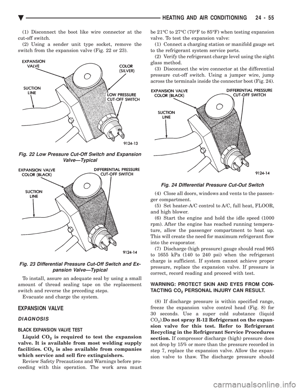
(1) Disconnect the boot like wire connector at the
cut-off switch. (2) Using a sender unit type socket, remove the
switch from the expansion valve (Fig. 22 or 23).
To install, assure an adequate seal by using a small
amount of thread sealing tape on the replacement
switch and reverse the preceding steps. Evacuate and charge the system.
EXPANSION VALVE
DIAGNOSIS
BLACK EXPANSION VALVE TEST
Liquid CO
2is required to test the expansion
valve. It is available from most welding supply
facilities. CO
2is also available from companies
which service and sell fire extinguishers. Review Safety Precautions and Warnings before pro-
ceeding with this operation. The work area must be 21ÉC to 27ÉC (70ÉF to 85ÉF) when testing expansion
valve. To test the expansion valve: (1) Connect a charging station or manifold gauge set
to the refrigerant system service ports. (2) Verify the refrigerant charge level using the sight
glass method. (3) Disconnect the wire connector at the differential
pressure cut-off switch. Using a jumper wire, jump
across the terminals inside the connector boot (Fig. 24).
(4) Close all doors, windows and vents to the passen-
ger compartment. (5) Set heater-A/C control to A/C, full heat, FLOOR,
and high blower. (6) Start the engine and hold the idle speed (1000
rpm). After the engine has reached running tempera-
ture, allow the passenger compartment to heat up.
This will create the need for maximum refrigerant flow
into the evaporator. (7) Discharge (high pressure) gauge should read 965
to 1655 kPa (140 to 240 psi) when the refrigerant
charge is sufficient. If system cannot achieve proper
pressure, replace the expansion valve. If pressure is
correct, record reading and proceed with test.
WARNING: PROTECT SKIN AND EYES FROM CON-
TACTING CO
2PERSONAL INJURY CAN RESULT.
(8) If discharge pressure is within specified range,
freeze the expansion valve control head (Fig. 8) for
30 seconds. Use a super cold substance (liquid
CO
2). Do not spray R-12 Refrigerant on the expan-
sion valve for this test. Refer to Refrigerant
Recycling in the Refrigerant Service Procedures
section. If compressor discharge (high) pressure does
not drop by 15% or more than the pressure recorded in
step 7, replace the expansion valve. Allow the expan-
sion valve to thaw. The discharge pressure should
Fig. 22 Low Pressure Cut-Off Switch and Expansion ValveÐTypical
Fig. 23 Differential Pressure Cut-Off Switch and Ex-pansion ValveÐTypical
Fig. 24 Differential Pressure Cut-Out Switch
Ä HEATING AND AIR CONDITIONING 24 - 55