1993 CHEVROLET PLYMOUTH ACCLAIM service indicator
[x] Cancel search: service indicatorPage 40 of 2438

LUBRICANTS AND GREASES
Lubricating grease is rated for quality and usage
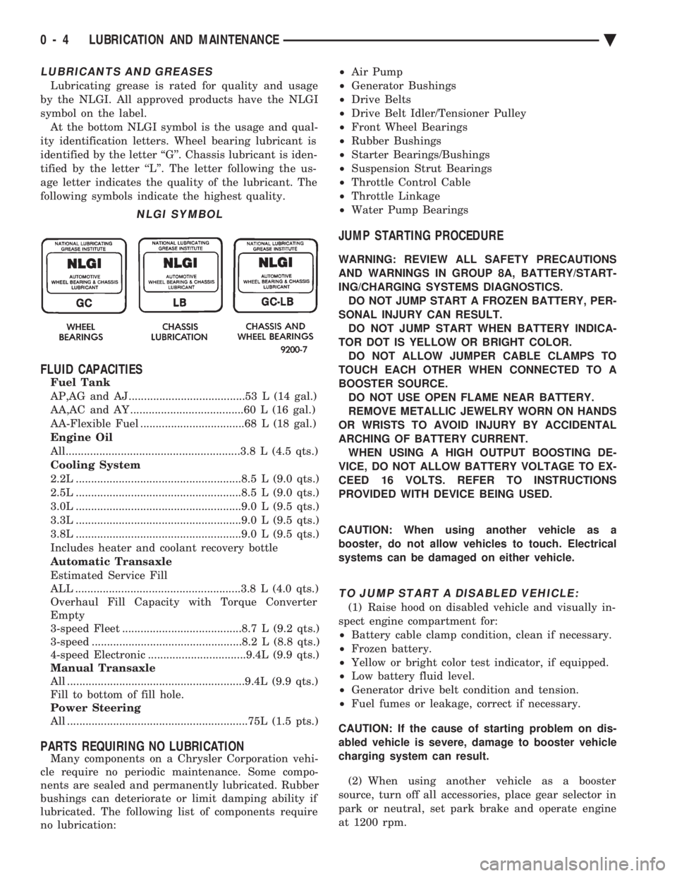
by the NLGI. All approved products have the NLGI
symbol on the label. At the bottom NLGI symbol is the usage and qual-
ity identification letters. Wheel bearing lubricant is
identified by the letter ``G''. Chassis lubricant is iden-
tified by the letter ``L''. The letter following the us-
age letter indicates the quality of the lubricant. The
following symbols indicate the highest quality.
FLUID CAPACITIES
Fuel Tank
AP,AG and AJ ......................................53 L (14 gal.)
AA,AC and AY .....................................60 L (16 gal.)
AA-Flexible Fuel ..................................68 L (18 gal.)
Engine Oil
All.........................................................3.8 L (4.5 qts.)
Cooling System
2.2L ......................................................8.5 L (9.0 qts.)
2.5L ......................................................8.5 L (9.0 qts.)
3.0L ......................................................9.0 L (9.5 qts.)
3.3L ......................................................9.0 L (9.5 qts.)
3.8L ......................................................9.0 L (9.5 qts.)
Includes heater and coolant recovery bottle
Automatic Transaxle
Estimated Service Fill
ALL ......................................................3.8 L (4.0 qts.)
Overhaul Fill Capacity with Torque Converter
Empty
3-speed Fleet .......................................8.7 L (9.2 qts.)
3-speed .................................................8.2 L (8.8 qts.)
4-speed Electronic ................................9.4L (9.9 qts.)
Manual Transaxle
All ..........................................................9.4L (9.9 qts.)
Fill to bottom of fill hole.
Power Steering
All ...........................................................75L (1.5 pts.)
PARTS REQUIRING NO LUBRICATION
Many components on a Chrysler Corporation vehi-
cle require no periodic maintenance. Some compo-
nents are sealed and permanently lubricated. Rubber
bushings can deteriorate or limit damping ability if
lubricated. The following list of components require
no lubrication: ²
Air Pump
² Generator Bushings
² Drive Belts
² Drive Belt Idler/Tensioner Pulley
² Front Wheel Bearings
² Rubber Bushings
² Starter Bearings/Bushings
² Suspension Strut Bearings
² Throttle Control Cable
² Throttle Linkage
² Water Pump Bearings
JUMP STARTING PROCEDURE
WARNING: REVIEW ALL SAFETY PRECAUTIONS
AND WARNINGS IN GROUP 8A, BATTERY/START-
ING/CHARGING SYSTEMS DIAGNOSTICS. DO NOT JUMP START A FROZEN BATTERY, PER-
SONAL INJURY CAN RESULT. DO NOT JUMP START WHEN BATTERY INDICA-
TOR DOT IS YELLOW OR BRIGHT COLOR. DO NOT ALLOW JUMPER CABLE CLAMPS TO
TOUCH EACH OTHER WHEN CONNECTED TO A
BOOSTER SOURCE. DO NOT USE OPEN FLAME NEAR BATTERY.
REMOVE METALLIC JEWELRY WORN ON HANDS
OR WRISTS TO AVOID INJURY BY ACCIDENTAL
ARCHING OF BATTERY CURRENT. WHEN USING A HIGH OUTPUT BOOSTING DE-
VICE, DO NOT ALLOW BATTERY VOLTAGE TO EX-
CEED 16 VOLTS. REFER TO INSTRUCTIONS
PROVIDED WITH DEVICE BEING USED.
CAUTION: When using another vehicle as a
booster, do not allow vehicles to touch. Electrical
systems can be damaged on either vehicle.
TO JUMP START A DISABLED VEHICLE:
(1) Raise hood on disabled vehicle and visually in-
spect engine compartment for:
² Battery cable clamp condition, clean if necessary.
² Frozen battery.
² Yellow or bright color test indicator, if equipped.
² Low battery fluid level.
² Generator drive belt condition and tension.
² Fuel fumes or leakage, correct if necessary.
CAUTION: If the cause of starting problem on dis-
abled vehicle is severe, damage to booster vehicle
charging system can result.
(2) When using another vehicle as a booster
source, turn off all accessories, place gear selector in
park or neutral, set park brake and operate engine
at 1200 rpm.
NLGI SYMBOL
0 - 4 LUBRICATION AND MAINTENANCE Ä
Page 45 of 2438

² SG service engine oil is a high quality crankcase
lubricant designed for use in all naturally aspirated
engines. If SG service engine oil is used in turbo-
charged engine, change engine oil at every 4 800
km (3,000 miles) or three months.
² SG/CD service engine oil is a high quality crank-
case lubricant designed for use in most naturally as-
pirated and turbocharged gasoline or diesel engines.
FLEXIBLE FUEL VEHICLES
Vehicles operated using Flexible Fuel (M85) re-
quire engine oil that meet or exceed Chrysler Stan-
dard MS-9214. Mopar Flexible Fuel engine oil or
equivalent should be used when adding or changing
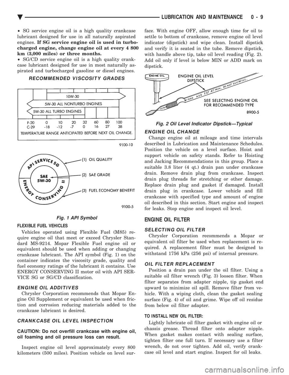
crankcase lubricant. The API symbol (Fig. 1) on the
container indicates the viscosity grade, quality and
fuel economy ratings of the lubricant it contains. Use
ENERGY CONSERVING II motor oil with API SER-
VICE SG or SG/CD classification.
ENGINE OIL ADDITIVES
Chrysler Corporation recommends that Mopar En-
gine Oil Supplement or equivalent be used when fric-
tion and corrosion reducing materials added to the
crankcase lubricant is desired.
CRANKCASE OIL LEVEL INSPECTION
CAUTION: Do not overfill crankcase with engine oil,
oil foaming and oil pressure loss can result.
Inspect engine oil level approximately every 800
kilometers (500 miles). Position vehicle on level sur- face. With engine OFF, allow enough time for oil to
settle to bottom of crankcase, remove engine oil level
indicator (dipstick) and wipe clean. Install dipstick
and verify it is seated in the tube. Remove dipstick,
with handle above tip, take oil level reading (Fig. 2).
Add oil only if level is below MIN or ADD mark on
dipstick.
ENGINE OIL CHANGE
Change engine oil at mileage and time intervals
described in Lubrication and Maintenance Schedules.
Position the vehicle on a level surface. Hoist and
support vehicle on safety stands. Refer to Hoisting
and Jacking Recommendations in this group. Place a
suitable 3.8 liter (4 qt.) drain pan under crankcase
drain. Remove drain plug from crankcase. Inspect
drain plug threads for stretching or other damage.
Replace drain plug and gasket if damaged. Install
drain plug in crankcase. Lower vehicle and fill
crankcase with specified type and amount of engine
oil described in this section. Start engine and inspect
for leaks. Stop engine and inspect oil level.
ENGINE OIL FILTER
SELECTING OIL FILTER
Chrysler Corporation recommends a Mopar or
equivalent oil filter be used when replacement is re-
quired. A replacement filter must be designed to
withstand 1756 kPa (256 psi) of internal pressure.
OIL FILTER REPLACEMENT
Position a drain pan under the oil filter. Using a
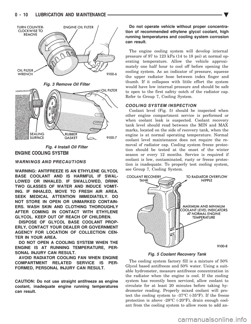
suitable oil filter wrench (Fig. 3) loosen filter. When
filter separates from adapter nipple, tip gasket end
upward to minimize oil spill. Remove filter from ve-
hicle. With a wiping cloth, clean the gasket sealing
surface (Fig. 4) of oil and grime. Wipe off oil residue
from below oil filter adapter.
TO INSTALL NEW OIL FILTER: Lightly lubricate oil filter gasket with engine oil or
chassis grease. Thread filter onto adapter nipple.
When gasket makes contact with sealing surface,
tighten filter one full turn. If necessary use a filter
wrench, do not over tighten. Add oil, verify crank-
case oil level and start engine. Inspect for oil leaks.
RECOMMENDED VISCOSITY GRADES
Fig. 1 API Symbol
Fig. 2 Oil Level Indicator DipstickÐTypical
Ä LUBRICATION AND MAINTENANCE 0 - 9
Page 46 of 2438

ENGINE COOLING SYSTEM
WARNINGS AND PRECAUTIONS
WARNING: ANTIFREEZE IS AN ETHYLENE GLYCOL
BASE COOLANT AND IS HARMFUL IF SWAL-
LOWED OR INHALED. IF SWALLOWED, DRINK
TWO GLASSES OF WATER AND INDUCE VOMIT-
ING. IF INHALED, MOVE TO FRESH AIR AREA.
SEEK MEDICAL ATTENTION IMMEDIATELY. DO
NOT STORE IN OPEN OR UNMARKED CONTAIN-
ERS. WASH SKIN AND CLOTHING THOROUGHLY
AFTER COMING IN CONTACT WITH ETHYLENE
GLYCOL. KEEP OUT OF REACH OF CHILDREN. DISPOSE OF GLYCOL BASE COOLANT PROP-
ERLY, CONTACT YOUR DEALER OR GOVERNMENT
AGENCY FOR LOCATION OF COLLECTION CEN-
TER IN YOUR AREA. DO NOT OPEN A COOLING SYSTEM WHEN THE
ENGINE IS AT RUNNING TEMPERATURE, PER-
SONAL INJURY CAN RESULT. AVOID RADIATOR COOLING FAN WHEN ENGINE
COMPARTMENT RELATED SERVICE IS PER-
FORMED, PERSONAL INJURY CAN RESULT.
CAUTION: Do not use straight antifreeze as engine
coolant, inadequate engine running temperatures
can result. Do not operate vehicle without proper concentra-
tion of recommended ethylene glycol coolant, high
running temperatures and cooling system corrosion
can result.
The engine cooling system will develop internal
pressure of 97 to 123 kPa (14 to 18 psi) at normal op-
erating temperature. Allow the vehicle approxi-
mately one half hour to cool off before opening the
cooling system. As an indicator of pressure, squeeze
the upper radiator hose between index finger and
thumb. If it collapses with little effort the system
would have low internal pressure and should be safe
to open to the first safety notch of the radiator cap.
Refer to Group 7, Cooling System.
COOLING SYSTEM INSPECTION
Coolant level (Fig. 5) should be inspected when
other engine compartment service is performed or
when coolant leak is suspected. Coolant recovery
tank level should read between the MIN and MAX
marks, located on the side of recovery tank, when the
engine is at normal operating temperature. Normal
coolant level maintenance does not require the re-
moval of radiator cap. Cooling system freeze protec-
tion should be tested at the onset of the winter
season or every 12 months. Service is required if
coolant is low, contaminated, rusty or freeze protec-
tion is inadequate. To properly test cooling system,
see Group 7, Cooling System.
The cooling system factory fill is a mixture of 50%
Glycol based antifreeze and 50% water. Using a suit-
able hydrometer, measure antifreeze concentration in
the radiator when the engine is cool. If the cooling
system has recently been serviced, allow coolant to
circulate for at least 20 minutes before taking hy-
drometer reading. Properly mixed coolant will pro-
tect the cooling system to -37ÉC (-35ÉF). If the freeze
protection is above -28ÉC (-20ÉF), drain enough cool-
ant from the cooling system to allow room to add an-
Fig. 3 Remove Oil Filter
Fig. 4 Install Oil Filter
Fig. 5 Coolant Recovery Tank
0 - 10 LUBRICATION AND MAINTENANCE Ä
Page 58 of 2438

BRAKE RESERVOIR LEVEL INSPECTION
WARNING: DO NOT ALLOW PETROLEUM OR WATER
BASE LIQUIDS TO CONTAMINATE BRAKE FLUID,
SEAL DAMAGE AND BRAKE FAILURE CAN RESULT.
RELIEVE PRESSURE IN ANTI-LOCK BRAKE SYS-
TEM BEFORE ADDING BRAKE FLUID TO RESER-
VOIR. IF NOT, BRAKE FLUID COULD DISCHARGED
FROM THE RESERVOIR POSSIBLY CAUSING PER-
SONAL INJURY.
The brake reservoir level should be inspected when
other under hood service is performed. It is normal
for the reservoir level to drop as disc brake pads
wear. When fluid must be added, use Mopar, Brake
Fluid or equivalent. Use only brake fluid conforming
to DOT 3, Federal, Department of Transportation
specification. To avoid brake fluid contamination, use
fluid from a properly sealed container. On vehicles with anti-lock brakes, depressurize the
system before inspecting fluid level. Turn OFF the
ignition and remove the key. Pump the brake pedal
at least 50 times to relieve the pressure in the sys-
tem.
On all vehicles, if fluid should become low after sev-
eral thousand kilometers (miles), fill the reservoir to
level marks on the side of the reservoir (Fig. 8 or 9).
HEADLAMPS
The headlamps should be inspected for intensity
and aim whenever a problem is suspected. When lug-
gage compartment is heavily loaded, the headlamp
aim should be adjusted to compensate for vehicle
height change. For proper service procedures, refer to
Group 8L, Lamps. DRIVER SUPPLEMENTAL AIRBAG SYSTEM
If the AIRBAG indicator lamp does not light at all,
stays lit or lights momentarily or continuously while
driving, a malfunction may have occurred. Prompt service is required. Refer to Group 8M, Restraint
Systems for proper diagnostic procedures.
BODY LUBRICATION
Body mechanisms and linkages should be inspected,
cleaned and lubricated as required to maintain ease of
operation and to prevent corrosion and wear. Before a component is lubricated, oil, grease and dirt
should be wiped off. If necessary, use solvent to clean
component to be lubricated. After lubrication is com-
plete, wipe off excess grease or oil. During winter season, external lock cylinders should
be lubricated with Mopar, Lock Lubricant or equiva-
lent to ensure proper operation when exposed to water
and ice. To assure proper hood latching component operation,
use engine oil to lubricate the lock, safety catch and
hood hinges when other under hood service is per-
formed. Mopar, Multi-purpose Grease or equivalent
should be applied sparingly to all pivot and slide
contact areas.
USE ENGINE OIL ON:
² Door hingesÐHinge pin and pivot points.
² Hood hingesÐPivot points.
² Luggage compartment lid hingesÐPivot points.
USE MOPAR LUBRIPLATE OR EQUIVALENT ON:
² Door check straps.
² Hood counterbalance springs.
² Luggage compartment lid latches.
² Luggage compartment lid prop rod pivots.
² Ash tray slides.
² Fuel Fill Door latch mechanism.
² Park brake mechanism.
² Front seat tracks.
Fig. 8 Anti-lock Brake Reservoir
Fig. 9 Master Cylinder Brake ReservoirÐExcept
Anti-lock
0 - 22 LUBRICATION AND MAINTENANCE Ä
Page 203 of 2438

BRAKE DISC (ROTOR) INDEX
page page
Braking Disc Removal ..................... 54
General Information ....................... 53
Inspection Diagnosis ...................... 53 Installing Braking Disc
..................... 54
Refinishing Braking Disc ................... 55
Service Procedures ....................... 53
GENERAL INFORMATION
Any servicing of the braking disc requires extreme
care to maintain the braking disc within service toler-
ances to ensure proper brake action.
CAUTION: If the braking disk (rotor) needs to be
replaced with a new part. The protective coating on
the braking surfaces of the rotor MUST BE REMOVED
with an appropriate solvent, to avoid contamination
of the brake shoe linings.
When replacing a rotor with a new part do NOT
reface the new rotor. Rotor already has the re-
quired micro finish when manufactured, only
remove the protective coating.
INSPECTION DIAGNOSIS
Before refinishing or refacing a braking disc, the disc
should be checked and inspected for the following
conditions: Braking surface scoring, rust, impregnation of lining
material and worn ridges. Excessive lateral rotor runout or wobble.
Thickness variation (Parallelism).
Dishing or distortion (Flatness).
If a vehicle has not been driven for a period of time.
The discs will rust in the area not covered by the brake
lining and cause noise and chatter when the brakes are
applied. Excessive wear and scoring of the disc can cause
temporary improper lining contact if ridges are not
removed before installation of new brake shoe assem-
blies. Some discoloration or wear of the disc surface is
normal and does not require resurfacing when linings
are replaced. Excessive runout or wobble in a disc can increase
pedal travel due to piston knock back. This will in-
crease guide pin bushing wear due to tendency of
caliper to follow disc wobble. Thickness variation in a disc can also result in pedal
pulsation, chatter and surge due to variation in brake
output. This can also be caused by excessive runout in
braking disc or hub. Dishing or distortion can be caused by extreme heat
and abuse of the brakes.
SERVICE PROCEDURES
CHECKING BRAKING DISC FOR RUNOUT AND THICKNESS
On vehicle, braking disc (rotor) runout is the com-
bination of the individual runout of the hub face and
the runout of the disc. (The hub and disc are separa-
ble). To measure runout on the vehicle, remove the
wheel and reinstall the lug nuts tightening the disc
to the hub. Mount Dial Indicator, Special Tool
C-3339 with Mounting Adaptor, Special Tool SP-1910
on steering arm. Dial indicator plunger should con-
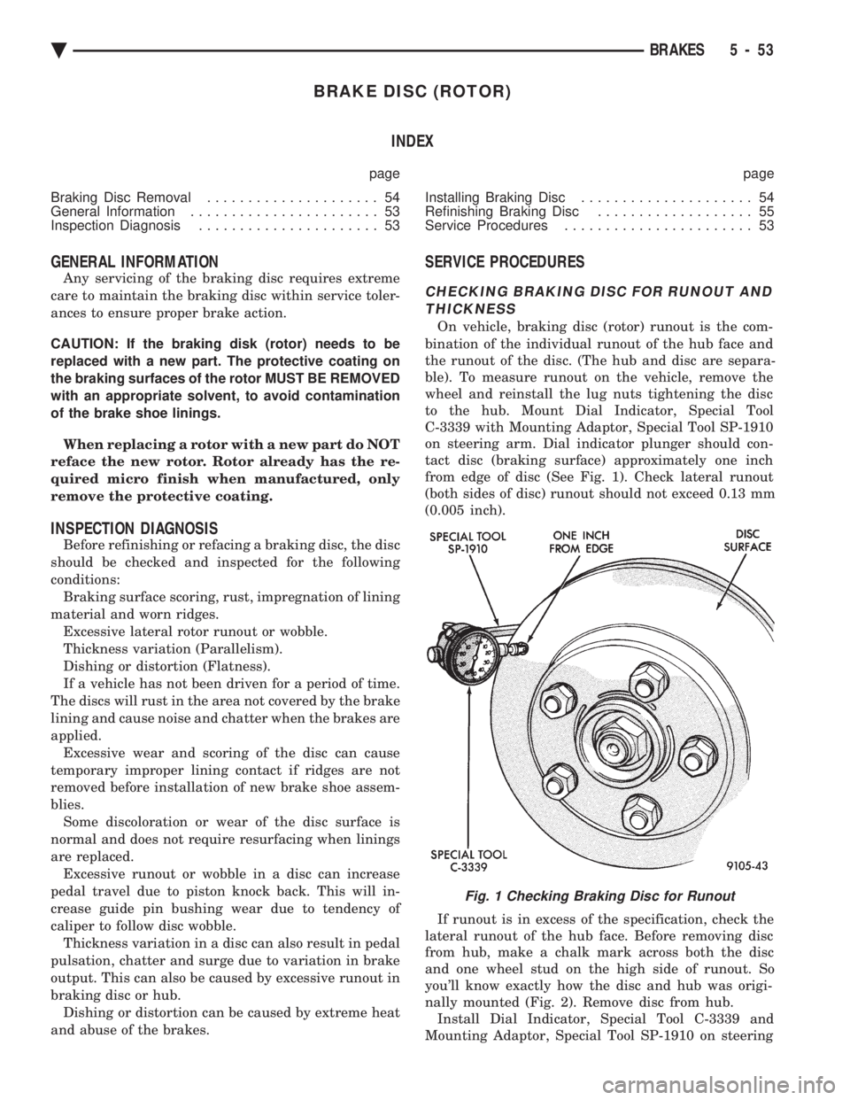
tact disc (braking surface) approximately one inch
from edge of disc (See Fig. 1). Check lateral runout
(both sides of disc) runout should not exceed 0.13 mm
(0.005 inch).
If runout is in excess of the specification, check the
lateral runout of the hub face. Before removing disc
from hub, make a chalk mark across both the disc
and one wheel stud on the high side of runout. So
you'll know exactly how the disc and hub was origi-
nally mounted (Fig. 2). Remove disc from hub. Install Dial Indicator, Special Tool C-3339 and
Mounting Adaptor, Special Tool SP-1910 on steering
Fig. 1 Checking Braking Disc for Runout
Ä BRAKES 5 - 53
Page 373 of 2438

BATTERY/STARTING/CHARGING SYSTEMS DIAGNOSTICS
CONTENTS
page page
BATTERY TEST PROCEDURES ON-VEHICLE . . 3
FAULT CODESÐON BOARD DIAGNOSTICS . . 23
GENERAL INFORMATION .................. 1
GENERATOR TEST PROCEDURES ON VEHICLE.19 IGNITION OFF DRAW (IOD)
............... 9
SPECIFICATIONS ....................... 28
STARTER TEST PROCEDURES ON VEHICLE . 11
GENERAL INFORMATION
² For Battery, Starter or Generator replacement re-
fer to Group 8B, Battery/Starter/Generator Service.
This Group 8A will cover diagnostics only. The Battery, Starting, and Charging Systems oper-
ate with one another, and must be thoroughly tested
as a complete system. To enable the vehicle to start
and charge properly, it must have a battery that will
perform to specifications. The starter motor, genera-
tor, wiring, and electronics also must perform within
specifications. Group 8A will cover Starting (Fig. 1)
and Charging System (Fig. 2) diagnostic procedures.
These will be covered from the most basic conven-
tional methods to On Board Diagnostics (OBD) built
into the vehicle's electronics. The need for conven-
tional testing equipment has not been eliminated by
the introduction of OBD. Frequent use of an amme-
ter, volt/ohmmeter, battery charger, carbon pile rheo-
stat (load tester), and 12 volt (low wattage) test light
will be required. All front wheel drive vehicles are equipped with
OBD and all OBD sensing systems are monitored by
the Powertrain Control Module. The Powertrain Con-
trol module will store in electronic memory, any de-
tectable failure within the monitored circuits. It will
retain this information for a period of 50 engine
starts, then erase the memory if the failure does not
reoccur during that period. This also will translate a
monitored failure as a FAULT CODE when a read-
out command is given. A readout command can be
made by turning the ignition switch to ON-OFF-ON-
OFF-ON without starting the engine. The Malfunc-
tion Indicator (CHECK ENGINE) Lamp on the
instrument cluster will flash in preset sequences to
show Fault Codes. However, the Malfunction Indica-
tor (Check Engine) Lamp cannot express fault codes
for all failures. Fault codes are easier to obtain and
more complete with the use of Diagnostic Tool (DRB
II). This tool is plugged into the diagnostic connector located in the engine compartment (Fig. 2). Refer to
the instructions provided with the (DRB II) tool be-
ing used. For numbered Fault Codes pertaining to compo-
nents within this Group, refer to Failure CodesÐOn
Board Diagnostics in Group 8A. For other Fault
Codes which, do not pertaining to this Group 8A, re-
fer to Group 14, Fuel System, On Board Diagnostics.
Fig. 1 Starting System Components
Ä BATTERY/STARTING/CHARGING SYSTEMS DIAGNOSTICS 8A - 1
Page 375 of 2438

BATTERY TEST PROCEDURES ON-VEHICLE INDEX
page page
Battery Charging .......................... 7
Battery Load Test ......................... 6
Battery Open Circuit Voltage Test ............. 4
Causes of Battery Discharging ............... 4 General Information
........................ 3
State of Charge Tests ...................... 4
Test Indicator ............................ 3
GENERAL INFORMATION
The battery stores, stabilizes, and produces electri-
cal current to operate various electrical systems in
the vehicle. The determination of whether a battery
is good or bad is made by the battery's ability to ac-
cept a charge. It also must produce high amperage
current output over an extended period to be able to
start the vehicle. The capability of the battery to
store electrical current comes from a chemical reac-
tion. This reaction takes place between the sulfuric
acid solution electrolyte and the lead +/- plates in
each cell of the battery. As the battery discharges,
the plates react with the acid from the electrolyte.
When the charging system charges the battery, the
water is converted to sulfuric acid in the battery. The
amount of acid, specific gravity in the electrolyte can
be measured with a hydrometer. The factory in-
stalled battery is equipped with a built in hydrome-
ter as a test indicator (Figs. 3, 4 and 5) to help in
determining the battery's state of charge. The factory
installed battery also is sealed. Water cannot and
should not be added.
The battery is vented to release gases that is cre-
ated when the battery is being charged and dis-
charged. The battery top, posts, and terminals should
be cleaned when other under hood maintenance is
performed (Fig. 3).
WARNING: DO NOT ASSIST BOOST, CHARGE, ADD
WATER, OR LOAD TEST BATTERY WHEN ELEC- TROLYTE LEVEL IS BELOW THE TOP OF THE
PLATES. PERSONAL INJURY MAY OCCUR.
When the electrolyte level is below the top of the
plates a yellow or bright color indicator in sight glass
(Figs. 4 and 5), the battery must be replaced. Refer
to Test Indicator. The battery must be completely
charged with a green color in sight glass. The top,
posts, and terminals should be properly cleaned be-
fore diagnostic procedures are performed. Also refer
to Group 8B, Battery/Starter/Generator Service.
TEST INDICATOR
The test indicator a hydrometer is viewed through
a sight glass, it is built into the top of battery case
(Figs. 3, 4 and 5). This provides visual information
for battery testing. The test indicator sight glass is to
be used with diagnostic procedures described in this
Group.
Fig. 3 Battery Construction and Test Indicator
Fig. 4 Built in Test Indicator
Fig. 5 Test Indicator Sight Glass
Ä BATTERY/STARTING/CHARGING SYSTEMS DIAGNOSTICS 8A - 3
Page 403 of 2438

BATTERY/STARTER/GENERATOR SERVICE
CONTENTS
page page
BATTERY REMOVAL, INSTALLATION AND SERVICE ............................. 1
GENERATOR ............................ 9 SPECIFICATIONS
....................... 12
STARTER ............................... 4
BATTERY REMOVAL, INSTALLATION AND SERVICE
GENERAL INFORMATION
This first section will cover Battery replacement and
service procedures only. For Battery diagnostic proce-
dures, refer to Group 8A, Battery/Starting/Charging
Systems Diagnostics. Factory installed batteries (Fig. 1) do not have re-
movable battery cell caps. Water cannot be added to
factory installed battery. Battery is sealed, except for
small vent holes in the top. Chemical composition
inside the battery produces an extremely small amount
of gases at normal charging voltages. The factory
installed battery is equipped with a test indicator that
displays a colored ball to show the battery's state of
charge.
² Green Indicator = Full charge
² Black Indicator = Discharged
² Yellow Indicator = Battery replacement required.
BATTERY VISUAL INSPECTION AND SERVICE
(1) Make sure ignition switch is in OFF position and
all accessories are OFF. (2) Disconnect and remove the battery cable termi-
nals from the battery posts. Remove negative cable
first (Fig. 2). WARNING: TO PROTECT THE HANDS FROM BAT-
TERY ACID, A SUITABLE PAIR OF HEAVY DUTY
RUBBER GLOVES, NOT THE HOUSEHOLD TYPE,
SHOULD BE WORN WHEN REMOVING OR SERVIC-
ING A BATTERY. SAFETY GLASSES ALSO SHOULD
BE WORN.
(3) Lift battery heat shield off battery, if equipped
(Fig. 3). (4) Remove battery hold down nut and clamp.
Fig. 1 Maintenance Free Battery
Fig. 2 Remove Battery Cables
Fig. 3 Battery Hold-Down
Ä BATTERY/STARTER/GENERATOR SERVICE 8B - 1