1993 CHEVROLET PLYMOUTH ACCLAIM compression ratio
[x] Cancel search: compression ratioPage 119 of 2438

A compression ball sleeve nut and sleeve for 3/16
inch tubing with ball sleeve connector and an inter-
nal pipe T-fitting. Can be used to attach the tubing
to the pressure gauge. (3) Cycle ignition from OFF to ON.
(4) Apply a load to the rear of the vehicle (two as-
sistants or approximately 300-325 lbs.) to run com-
pressor and raise the vehicle. (5) Remove the load applied in Step 4. Allow the
system to exhaust and lower the vehicle. (6) When no more air can be exhausted, the gauge
should indicate 69 to 152 kPa (10 to 22 psi). (7) Remove the pressure gauge and nylon tubing.
Attach the air line between the dryer and shock ab-
sorber. Repeat Steps 3, 4, and 5 to ensure system air
pressure is in the shocks.
LEAK CHECKS
(1) Repeat Residual Air Check Steps 1, 2, 3, and 4.
Allow the system to fill until gauge reads 483 to 621
kPa (70 to 90 psi). If compressor is permitted to run until it reaches
its maximum output pressure, the vent solenoid
valve will function as a relief valve. The resulting
leak down, when compressor shuts off, will indicate a
false air leak. (2) With load still applied, disconnect wire harness
connector from the control module, then remove ap-
plied load. Vehicle should rise. Cycle ignition switch
to OFF. (3) Observe if pressure leaks down or holds steady
(wait approximately 15 minutes). (A) If system will not inflate beyond 345 kPa (50
psi). A severe leak may be indicated. Check for a
pinched pressure line between compressor and
shocks. (B) The standard soap solution check procedure is
acceptable. (C) If pressure holds steady, perform the diagnosis
procedures.
SYSTEM OPERATION
RAISING VEHICLE HEIGHT
When weight is added to the rear suspension. The
body of the vehicle is lowered, moving the height
sensor down. This action will activate the internal time delay
circuit. After a time delay of 12 to 18 seconds. The
control module (CM) activates the ground circuit to
the compressor relay. With the relay energized, the compressor motor
runs and air is sent through the system. As the
shock absorbers inflate, the body moves upward to a
corrected position. When the body reaches the correct
height, the control module (CM) stops the compressor
operation.
LOWERING VEHICLE HEIGHT
When the weight is removed from the vehicle. The
body moves upward, which allows the height sensor
to move upward and activate the internal time delay
circuit. After a time delay of 12 to 18 seconds. The (CM)
activates the exhaust solenoid circuit. Air is ex-
hausted from the shock absorbers through the air
dryer and exhaust solenoid to the atmosphere. As the body lowers, the height sensor is lowered to-
ward its original position. When the body reaches the
original vehicle height, the (CM) opens the exhaust
solenoid valve circuit.
COMPRESSOR PERFORMANCE TEST
This test can be performed on the vehicle. It is
used to evaluate compressor current draw, pressure
output, and leak down. (1) Disconnect the compressor motor wiring har-
ness connector. (2) Disconnect air line between dryer and right
shock absorber. (3) Connect an air pressure gauge into the system
(Fig. 5). (4) Connect an ammeter in series between the red
wire terminal on compressor connector and a 12 volt
power source. Also, connect a ground wire from the
black wire terminal on the compressor connector to a
good ground on the frame (Fig. 6). (5) If the current draw to the compressor motor ex-
ceeds 21 amperes, replace the compressor assembly. (6) When the air pressure stabilizes at 827 kPa
(120 psi), disconnect the (+) wire lead from the con-
nector. Replace the compressor assembly if any of the
following conditions exists:
Fig. 5 Pressure Gauge Installed in System
Ä SUSPENSION AND DRIVESHAFTS 2 - 61
Page 162 of 2438

ing inserted in jaws but do not apply heavy pressure
to handle as this will lock tubing in place.Place gauge (Form A) on edge over end of brake
tubing. Push tubing through jaws until end of tubing
contacts the recessed notch in gauge matching the
tubing size. Squeeze handles of flaring tool and lock
tubing in place. Place 3/16 inch plug of gauge (A)
down in end of tubing. Swing compression disc over
gauge and center tapered flaring screw in recess of
disc. Screw in until plug gauge has seated on jaws of
flaring tool. This action has started to invert the ex- tended end of the tubing. Remove gauge and continue
to screw down until tool is firmly seated in tubing.
Remove tubing from flaring tool and inspect seat. Refer
to routing diagrams (Figs. 18 to 21) for proper routing
and clip location. Replace any damaged tube routing
clips.
ISO TUBING FLARES
CAUTION: All ISO style tubing flares (Fig. 13 & 16 ) are
of metric dimensions. When performing any service
procedures on vehicles using ISO style tubing flares,
metric size tubing of 4.75 mm MUST be used with
metric ISO tube flaring equipment.
To create a (metric) ISO style tubing flare, Use
Snap-On Flaring Tool TFM-428, or equivalent. See
(Fig. 17) and proceed with the steps listed below. Be
sure to place the tubing nut on the tube before
flaring the tubing. (1) Carefully prepare the end of the tubing to be
flared. Be sure the end of the tubing to be flared is
square and all burrs on the inside of the tubing are
removed (Fig. 15). This preparation is essential to
obtain the correct form of a (metric) ISO tubing
flare. (2) Open the jaws of the Flaring Tool. Align the
mating size jaws of the flaring tool around the size of
the tubing to be flared. Close the jaws of the Flaring
Tool around the tubing to keep it from sliding out of the
flaring tool, but do not lock the tubing in place. See
(Fig. 17)
Fig. 14 Cutting and Flaring of Brake Line Tubing
Fig. 15 Brake Tube Preparation For Flaring
Fig. 16 Double Flare And ISO-Flare Tubing Connec- tions
5 - 12 BRAKES Ä
Page 473 of 2438

tion timing from the crankshaft position sensor. Once
crankshaft position has been determined, the PCM
begins energizing the injectors in sequence.On Turbo III engines, the crankshaft position sensor
is located in the transaxle housing, below the throttle
body (Fig. 26). On 3.3L and 3.8L engines, the crank-
shaft position sensor is located in the transaxle hous-
ing (Fig. 27). The bottom of the sensor is positioned next to the
drive plate. The distance between the bottom of
sensor and the drive plate is critical to the op-
eration of the system. When servicing the crank-
shaft sensor, refer to the 3.3L Ignition
SystemÐService Procedures section in this
Group.IGNITION COIL
WARNING: THE DIRECT IGNITION SYSTEM GENER-
ATES APPROXIMATELY 40,000 VOLTS. PERSONAL
INJURY COULD RESULT FROM CONTACT WITH
THIS SYSTEM.
The 3.3L and 3.8L coil assembly consists of 3 coils
molded together (Fig. 28). The assembly is mounted
on the intake manifold. The 2.2L Turbo III coil as-
sembly consists of 2 coils molded together (Fig. 29).
The assembly is mounted at the front of the engine.
For all engines, the number of each coil appears on
the front of the coil pack.
High tension leads route to each cylinder from the
coil. The coil fires two spark plugs every power
stroke. One plug is the cylinder under compression,
the other cylinder fires on the exhaust stroke. The
PCM determines which of the coils to charge and fire
at the correct time. On 3.3L and 3.8L engines, coil one fires cylinders 1
and 4, coil two fires cylinders 2 and 5, coil three fires
cylinders three and six.
Fig. 28 Coil PackÐ2.2L Turbo III Engine
Fig. 29 Coil PackÐ3.3L and 3.8L Engines
Fig. 26 Crankshaft Position Sensor LocationÐTurbo III Engines
Fig. 27 Crankshaft Position Sensor LocationÐ3.3Land 3.8L Engines
Ä IGNITION SYSTEMS 8D - 31
Page 1575 of 2438
Flexible fuel vehicles can operate on a mixture of
up to 85 percent methanol, 15 percent unleaded gas-
oline. These vehicles also operate on mixtures con-
taining a lower percentage of methanol or just pure
unleaded gasoline. Engine components which are required for safe op-
eration using fuel containing methanol alcohol are
identified by a standard green color and/or display
the statement methanol compatible imprinted on the
component. To ensure continued safe operation, these
components must be serviced only with genuine MO-
PAR replacement parts. Methanol compatible parts for the 2.5L FFV (Flex-
ible Fuel Vehicle) engine include, but are not limited
to; the valve stem oil seals, all piston rings, the oil
fill cap, the fuel injectors, fuel rail, fuel pressure reg-
ulator, hoses and the vacuum control harness hose. BLOCK: All four cylinder cast iron blocks have
cast-in recesses in the bottom of each cylinder bore to
provide connecting rod clearance; especially needed
for 2.5L engines. The bores are also siamese to min-
imize engine length. A coolant passage is drilled
cross-ways through the siamese section to enhance
between the bore cooling on some engine types. A
partial open deck is used for cooling and weight re-
duction with oil filter, water pump, and distributor
mounting bosses molded into the front (radiator side)
of the block. Nominal wall thickness is 4.5 mm. Five
main bearing bulkheads and a block skirt extending
3 mm below the crankshaft center line add to the
blocks high rigidity with light weight. CRANKSHAFT: A nodular cast iron crankshaft is
used in TBI engines. A forged steel crankshaft is
used in the Turbo III engine. All engines have 5 main bearings, with number 3 flanged to control
thrust. The 60 mm diameter main and 50 mm diam-
eter crank pin journals (all) have undercut radiuses
fillets that are deep rolled for added strength. To op-
timize bearing loading 4 counterweights are used.
Hydrodynamic seals (installed in diecast aluminum
retainers) provide end sealing, where the crankshaft
exits the block. Anaerobic gasket material is used for
retainer-to-block sealing. No vibration damper is
used. A sintered iron (TBI engine and steel billet
Turbo III engines) timing belt sprocket is mounted
on the crankshaft nose. This sprocket provides mo-
tive power; via timing belt to the camshaft and inter-
mediate shaft sprockets (also sintered iron (TBI
engine and steel billet Turbo III engines) providing
timed valve, distributor, and oil pump actuation. PISTONS: Some Chrysler pistons have cast-in
steel struts at the pin bosses for autothermic control.
All 2.2L and 2.5L piston tops have cuts to provide
valve clearance. Some pistons are dished to provide
various compression ratios. Standard 2.2L and 2.5L
engines are designed for 9.5:1 and 8.9:1 compression
ratios respectively. The 2.5L piston is dished and is a
lightweight design to enhance engine smoothness.
The 2.2L turbo III uses dished pistons providing a
8.3:1 compression ratio. All standard 2.2/2.5L and
2.5L FFV engines use pressed-in piston pins to at-
tach forged steel connecting rods, 2.2L turbo III en-
gine uses a full floating piston pin and connecting
rod assembly. PISTONS RINGS: The 2.2/2.5L engines share
common piston rings throughout, including molybde-
num filled top ring for reliable compression sealing
and a tapered faced intermediate ring for additional
cylinder pressure control. The 2.5L FFV engine fea-
ture all chrome rings for enhanced long term dura-
bility under multi-fueled conditions. CYLINDER HEAD: The cylinder head is cast alu-
minum with in-line valves. The 2.2/2.5L and 2.5L
FFV valves are arranged with alternating exhaust
and intake. The intake and exhaust ports are located
in the rearward, facing side of the head. The Turbo
III valves are arranged in two inline banks, with the
ports of the bank of two intake valves per cylinder
facing toward the radiator side of engine and ports of
the bank of two exhaust valve per cylinder facing to-
ward the dash panel. The intake ports feed fast-burn
design combustion chambers (2.2/2.5L and 2.5L FFV
only) with the spark plug located close to the center
line of the combustion chamber for optimum effi-
ciency. An integral oil gallery within the cylinder
head supplies oil to the hydraulic lash adjusters,
camshaft, and valve mechanisms. CAMSHAFT: The nodular iron camshaft has five
bearing journals (2.2/2.5L and 2.5L FFV). The Turbo
III employs dual camshafts that have nine bearing
journals. Flanges at the rear journal control cam-
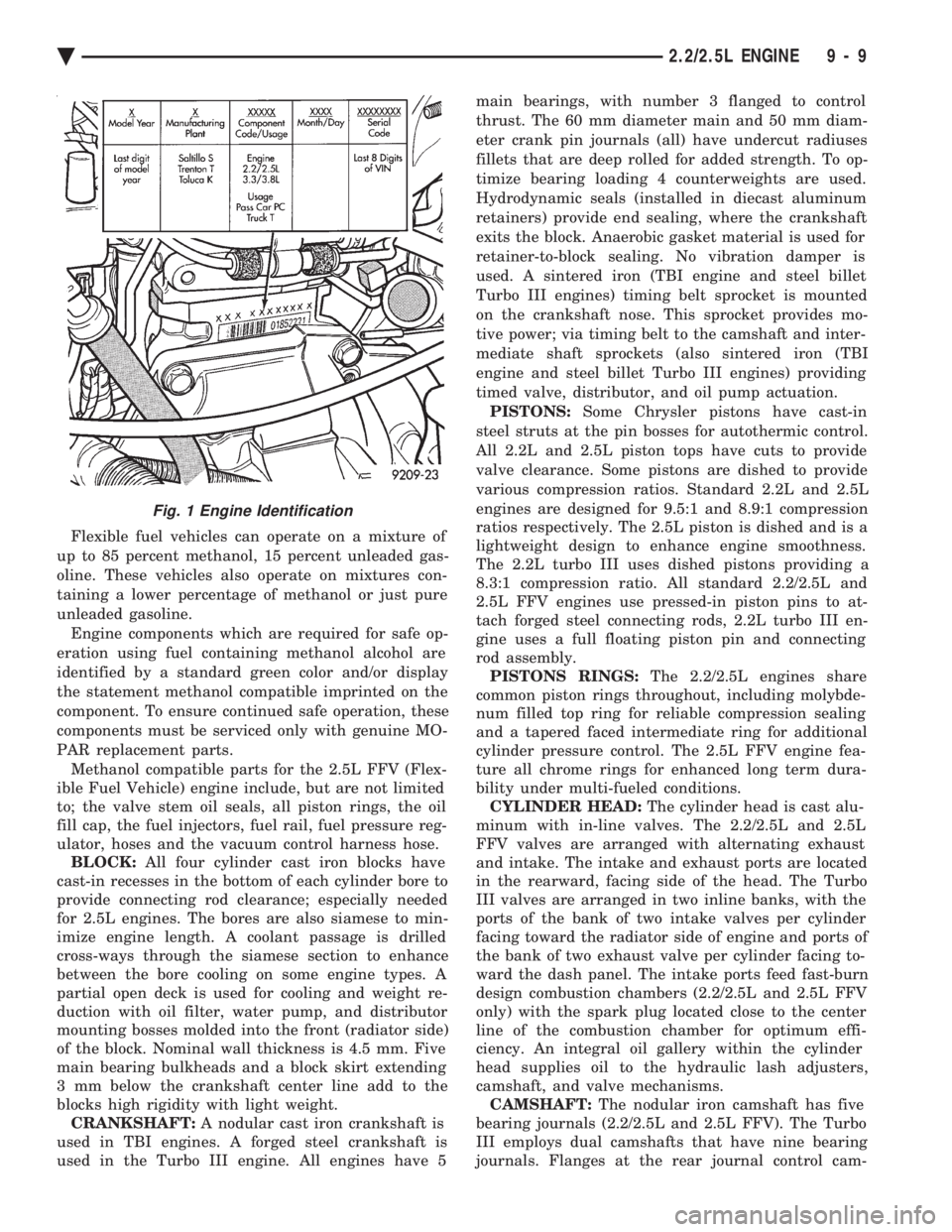
Fig. 1 Engine Identification
Ä 2.2/2.5L ENGINE 9 - 9
Page 1620 of 2438
firmly and press down the portion to be installed un-
til side rail is in position. Do not use a piston ring
expander. (Fig. 19).
(3) Install upper side rail first and then the lower
side rail. (4) Install No. 2 piston ring and then No. 1 piston
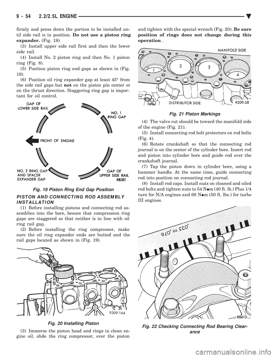
ring (Fig. 8). (5) Position piston ring end gaps as shown in (Fig.
19). (6) Position oil ring expander gap at least 45É from
the side rail gaps but noton the piston pin center or
on the thrust direction. Staggering ring gap is impor-
tant for oil control.
PISTON AND CONNECTING ROD ASSEMBLY INSTALLATION
(1) Before installing pistons and connecting rod as-
semblies into the bore, besure that compression ring
gaps are staggered so that neither is in line with oil
ring rail gap. (2) Before installing the ring compressor, make
sure the oil ring expander ends are butted and the
rail gaps located as shown in (Fig. 19).
(3) Immerse the piston head and rings in clean en-
gine oil, slide the ring compressor, over the piston and tighten with the special wrench (Fig. 20).
Be sure
position of rings does not change during this
operation .
(4) The valve cut should be toward the manifold side
of the engine (Fig. 21). (5) Install connecting rod bolt protectors on rod bolts
(Fig. 4). (6) Rotate crankshaft so that the connecting rod
journal is on the center of the cylinder bore. Insert rod
and piston into cylinder bore and guide rod over the
crankshaft journal. (7) Tap the piston down in cylinder bore, using a
hammer handle. At the same time, guide connecting
rod into position on connecting rod journal. (8) Install rod caps. Install nuts on cleaned and oiled
rod bolts and tighten nuts to 54 N Im (40 ft. lb.) Plus 1/4
turn for N/A engines and 68 N Im (50 ft. lbs.) for turbo
III engines.
Fig. 19 Piston Ring End Gap Position
Fig. 20 Installing Piston
Fig. 21 Piston Markings
Fig. 22 Checking Connecting Rod Bearing Clear- ance
9 - 54 2.2/2.5L ENGINE Ä
Page 1664 of 2438
3.3/3.8L ENGINE INDEX
page page
Camshaft .............................. 112
Camshaft BearingsÐEngine Removed From Vehicle .............................. 113
Checking Engine Oil Pressure .............. 125
Connecting Rods ........................ 118
Crankshaft Oil Seals Service ............... 121
Crankshaft Service ...................... 118
Cylinder Block, Piston and Connecting Rod Assembly Service ...................... 114
Cylinder Heads ......................... 102
Engine Assembly ........................ 101
Engine Core Oil and Cam Plugs ............ 113
Engine Lubrication System ................ 122 Engine Mounts
.......................... 99
Engine Specifications ..................... 126
General Information ....................... 98
Hydraulic Tappets ....................... 108
Installing Piston and Connecting Rod Assembly . 117
Intake Manifold Sealing ................... 104
Oil Filter .............................. 125
Oil Pan Service ......................... 122
Oil Pump Service ....................... 123
Rocker Arms and Shaft Assembly ........... 102
Timing Chain Cover, Oil Seal and Chain ...... 109
Valve Service .......................... 104
Valve Timing ........................... 109
GENERAL INFORMATION
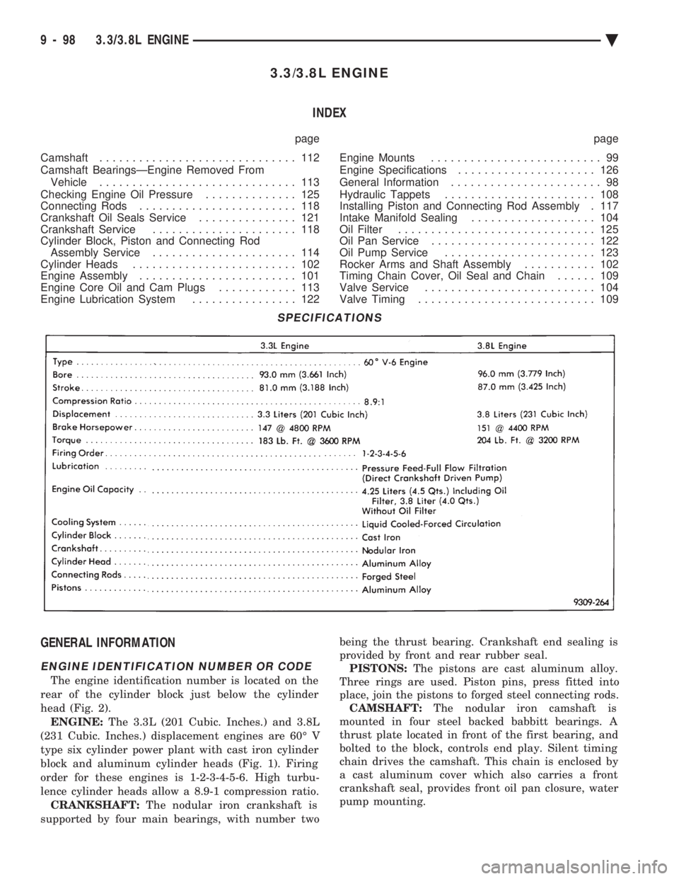
ENGINE IDENTIFICATION NUMBER OR CODE
The engine identification number is located on the
rear of the cylinder block just below the cylinder
head (Fig. 2). ENGINE: The 3.3L (201 Cubic. Inches.) and 3.8L
(231 Cubic. Inches.) displacement engines are 60É V
type six cylinder power plant with cast iron cylinder
block and aluminum cylinder heads (Fig. 1). Firing
order for these engines is 1-2-3-4-5-6. High turbu-
lence cylinder heads allow a 8.9-1 compression ratio. CRANKSHAFT: The nodular iron crankshaft is
supported by four main bearings, with number two being the thrust bearing. Crankshaft end sealing is
provided by front and rear rubber seal. PISTONS: The pistons are cast aluminum alloy.
Three rings are used. Piston pins, press fitted into
place, join the pistons to forged steel connecting rods. CAMSHAFT: The nodular iron camshaft is
mounted in four steel backed babbitt bearings. A
thrust plate located in front of the first bearing, and
bolted to the block, controls end play. Silent timing
chain drives the camshaft. This chain is enclosed by
a cast aluminum cover which also carries a front
crankshaft seal, provides front oil pan closure, water
pump mounting.
SPECIFICATIONS
9 - 98 3.3/3.8L ENGINE Ä
Page 1683 of 2438
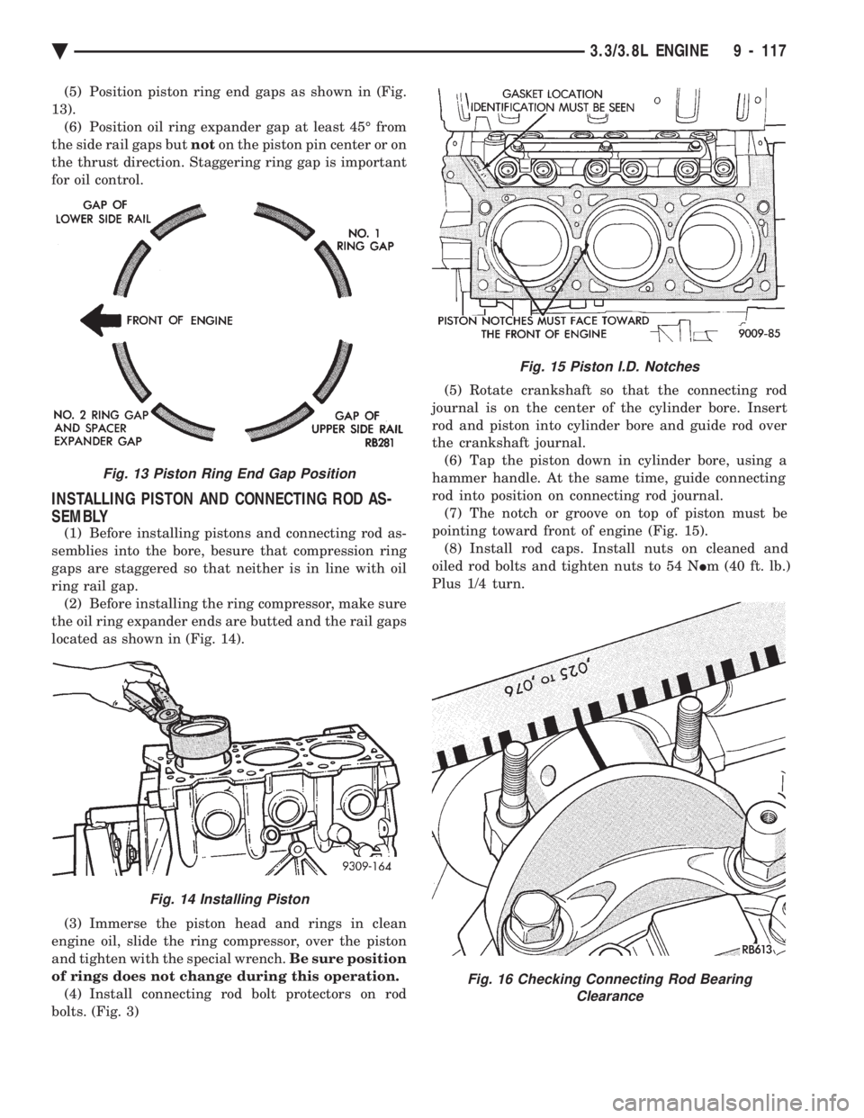
(5) Position piston ring end gaps as shown in (Fig.
13). (6) Position oil ring expander gap at least 45É from
the side rail gaps but noton the piston pin center or on
the thrust direction. Staggering ring gap is important
for oil control.
INSTALLING PISTON AND CONNECTING ROD AS-
SEMBLY
(1) Before installing pistons and connecting rod as-
semblies into the bore, besure that compression ring
gaps are staggered so that neither is in line with oil
ring rail gap. (2) Before installing the ring compressor, make sure
the oil ring expander ends are butted and the rail gaps
located as shown in (Fig. 14).
(3) Immerse the piston head and rings in clean
engine oil, slide the ring compressor, over the piston
and tighten with the special wrench. Be sure position
of rings does not change during this operation. (4) Install connecting rod bolt protectors on rod
bolts. (Fig. 3) (5) Rotate crankshaft so that the connecting rod
journal is on the center of the cylinder bore. Insert
rod and piston into cylinder bore and guide rod over
the crankshaft journal. (6) Tap the piston down in cylinder bore, using a
hammer handle. At the same time, guide connecting
rod into position on connecting rod journal. (7) The notch or groove on top of piston must be
pointing toward front of engine (Fig. 15). (8) Install rod caps. Install nuts on cleaned and
oiled rod bolts and tighten nuts to 54 N Im (40 ft. lb.)
Plus 1/4 turn.
Fig. 15 Piston I.D. Notches
Fig. 16 Checking Connecting Rod Bearing Clearance
Fig. 13 Piston Ring End Gap Position
Fig. 14 Installing Piston
Ä 3.3/3.8L ENGINE 9 - 117
Page 1782 of 2438
once the system has entered closed loop. Refer to
Modes of Operation in this section for an explanation
of closed loop operation.
NON-MONITORED CIRCUITS
The PCM does not monitor the following circuits,
systems and conditions that could have malfunctions
that result in driveability problems. Diagnostic trou-
ble codes may not be displayed for these conditions.
However, problems with these systems may cause di-
agnostic trouble codes to be displayed for other sys-
tems. For example, a fuel pressure problem will not
register a fault directly, but could cause a rich or
lean condition. This could cause an oxygen sensor
fault to be stored in the PCM. Fuel Pressure - Fuel pressure is controlled by the
fuel pressure regulator. The PCM cannot detect a
clogged fuel pump inlet filter, clogged in-line fuel fil-
ter, or a pinched fuel supply or return line. However,
these could result in a rich or lean condition causing
an oxygen sensor fault. Secondary Ignition Circuit - The PCM cannot
detect an inoperative ignition coil, fouled or worn
spark plugs, ignition cross firing, or open spark plug
cables. Engine Timing - The PCM cannot detect an incor-
rectly indexed timing chain, camshaft sprocket and
crankshaft sprocket. The PCM also cannot detect an
incorrectly indexed distributor. However, these could
result in a rich or lean condition causing an oxygen
sensor fault to be stored in the PCM. Cylinder Compression - The PCM cannot detect
uneven, low, or high engine cylinder compression. Exhaust System
- The PCM cannot detect a
plugged, restricted or leaking exhaust system. Fuel Injector Malfunctions - The PCM cannot
determine if the fuel injector is clogged, the pintle is
sticking or the wrong injector is installed. However,
these could result in a rich or lean condition causing
an oxygen sensor fault to be stored in the PCM. Excessive Oil Consumption - Although the PCM
monitors the exhaust stream oxygen content through
the oxygen sensor when the system is in closed loop,
it cannot determine excessive oil consumption. Throttle Body Air Flow - The PCM cannot detect
a clogged or restricted air cleaner inlet or filter ele-
ment. Evaporative System - The PCM will not detect a
restricted, plugged or loaded evaporative purge can-
ister. Vacuum Assist - Leaks or restrictions in the vac-
uum circuits of vacuum assisted engine control sys-
tem devices are not monitored by the PCM. However,
these could result in a MAP sensor fault being stored
in the PCM. PCM System Ground - The PCM cannot deter-
mine a poor system ground. However, a diagnostic
trouble code may be generated as a result of this con-
dition. PCM Connector Engagement - The PCM cannot
determine spread or damaged connector pins. How-
ever, a diagnostic trouble code may be generated as a
result of this condition.
HIGH AND LOW LIMITS
The powertrain control module (PCM) compares in-
put signal voltages from each input device with es-
tablished high and low limits that are programmed
into it for that device. If the input voltage is not
within specifications and other diagnostic trouble
code criteria are met, a diagnostic trouble code will
be stored in memory. Other diagnostic trouble code
criteria might include engine RPM limits or input
voltages from other sensors or switches that must be
present before a fault condition can be verified.
DIAGNOSTIC TROUBLE CODE DESCRIPTION
When a diagnostic trouble code appears, it indi-
cates the powertrain control module (PCM) has rec-
ognized an abnormal condition in the system.
Diagnostic trouble codes can be obtained from the
malfunction indicator lamp (instrument panel Check
Engine lamp) on the Instrument Panel or from the
DRBII scan tool. Diagnostic trouble codes indicate
the results of a failure but do not identify the failed
component directly.
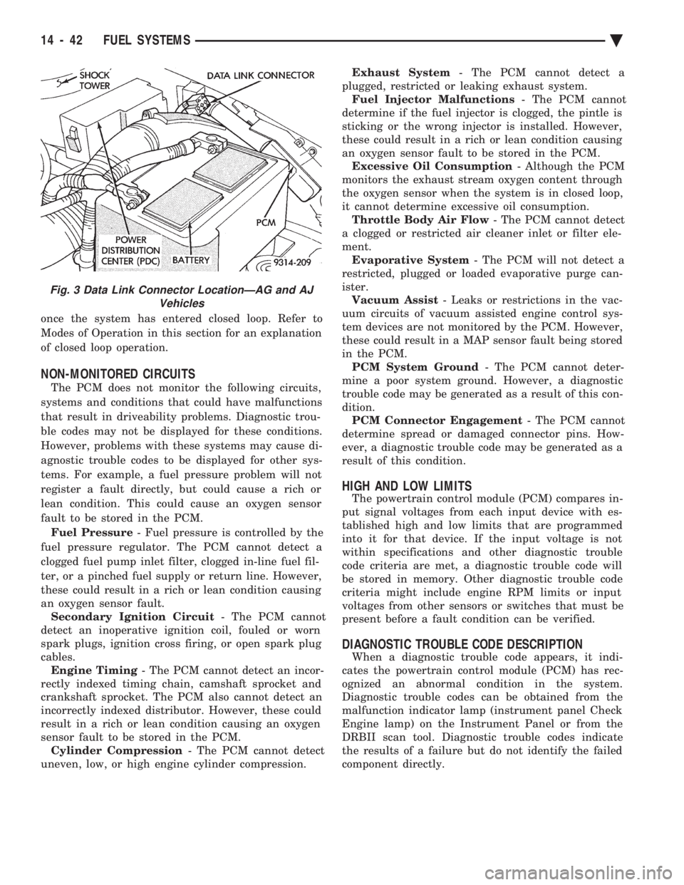
Fig. 3 Data Link Connector LocationÐAG and AJ Vehicles
14 - 42 FUEL SYSTEMS Ä