1993 CHEVROLET PLYMOUTH ACCLAIM service indicator
[x] Cancel search: service indicatorPage 1603 of 2438
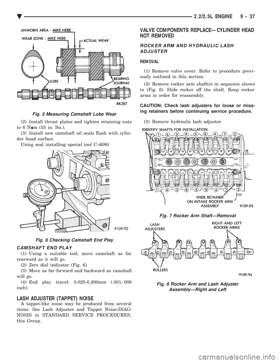
(2) Install thrust plates and tighten retaining nuts
to6N Im (55 in. lbs.).
(3) Install new camshaft oil seals flush with cylin-
der head surface. Using seal installing special tool C-4680.
CAMSHAFT END PLAY
(1) Using a suitable tool, move camshaft as far
rearward as it will go. (2) Zero dial indicator (Fig. 6).
(3) Move as far forward and backward as camshaft
will go. (4) End play travel: 0.025-0.200mm (.001-.008
inch).
LASH ADJUSTER (TAPPET) NOISE
A tappet-like noise may be produced from several
items. See Lash Adjuster and Tappet Noise-DIAG-
NOSIS in STANDARD SERVICE PROCEDURES,
this Group.
VALVE COMPONENTS REPLACEÐCYLINDER HEAD
NOT REMOVED
ROCKER ARM AND HYDRAULIC LASH
ADJUSTER
REMOVAL
(1) Remove valve cover. Refer to procedure previ-
ously outlined in this section.
(2) Remove rocker arm shaft(s) in sequence shown
in (Fig. 6). Slide rocker off the shaft. Keep rocker
arms in order for reassembly.
CAUTION: Check lash adjusters for loose or miss-
ing retainers before continuing service procedure.
(3) Remove hydraulic lash adjuster.
Fig. 5 Measuring Camshaft Lobe Wear
Fig. 6 Checking Camshaft End Play
Fig. 7 Rocker Arm ShaftÐRemoval
Fig. 8 Rocker Arm and Lash Adjuster AssemblyÐRight and Left
Ä 2.2/2.5L ENGINE 9 - 37
Page 1609 of 2438
CRANKSHAFT SERVICE
CRANKSHAFT MAIN BEARINGS
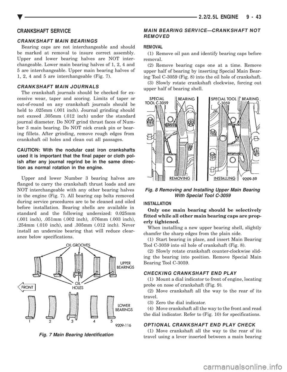
Bearing caps are not interchangeable and should
be marked at removal to insure correct assembly.
Upper and lower bearing halves are NOT inter-
changeable. Lower main bearing halves of 1, 2, 4 and
5 are interchangeable. Upper main bearing halves of
1, 2, 4 and 5 are interchangeable (Fig. 7).
CRANKSHAFT MAIN JOURNALS
The crankshaft journals should be checked for ex-
cessive wear, taper and scoring. Limits of taper or
out-of-round on any crankshaft journals should be
held to .025mm (.001 inch). Journal grinding should
not exceed .305mm (.012 inch) under the standard
journal diameter. Do NOT grind thrust faces of Num-
ber 3 main bearing. Do NOT nick crank pin or bear-
ing fillets. After grinding, remove rough edges from
crankshaft oil holes and clean out all passages.
CAUTION: With the nodular cast iron crankshafts
used it is important that the final paper or cloth pol-
ish after any journal regrind be in the same direc-
tion as normal rotation in the engine.
Upper and lower Number 3 bearing halves are
flanged to carry the crankshaft thrust loads and are
NOT interchangeable with any other bearing halves
in the engine (Fig. 7). All bearing cap bolts removed
during service procedures are to be cleaned and oiled
before installation. Bearing shells are available in
standard and the following undersized: 0.025mm
(.001 inch), .051mm (.002 inch), .076mm (.003 inch),
.254mm (.010 inch), and .305mm (.012 inch). Never
install an undersize bearing that will reduce clear-
ance below specifications.
MAIN BEARING SERVICEÐCRANKSHAFT NOT REMOVED
REMOVAL
(1) Remove oil pan and identify bearing caps before
removal. (2) Remove bearing caps one at a time. Remove
upper half of bearing by inserting Special Main Bear-
ing Tool C-3059 (Fig. 8) into the oil hole of crankshaft. (3) Slowly rotate crankshaft clockwise, forcing out
upper half of bearing shell.
INSTALLATION Only one main bearing should be selectively
fitted while all other main bearing caps are prop-
erly tightened. When installing a new upper bearing shell, slightly
chamfer the sharp edges from the plain side. (1) Start bearing in place, and insert Main Bearing
Tool C-3059 into oil hole of crankshaft (Fig. 8). (2) Slowly rotate crankshaft counter-clockwise slid-
ing the bearing into position. Remove Special Main
Bearing Tool C-3059.
CHECKING CRANKSHAFT END PLAY
(1) Mount a dial indicator to front of engine, locating
probe on nose of crankshaft (Fig. 9). (2) Move crankshaft all the way to the rear of its
travel. (3) Zero the dial indicator.
(4) Move crankshaft all the way to the front and read
the dial indicator. Refer to (Fig. 10) for specifications.
OPTIONAL CRANKSHAFT END PLAY CHECK
(1) Move crankshaft all the way to the rear of its
travel using a lever inserted between a main bearingFig. 7 Main Bearing Identification
Fig. 8 Removing and Installing Upper Main Bearing With Special Tool C-3059
Ä 2.2/2.5L ENGINE 9 - 43
Page 1654 of 2438
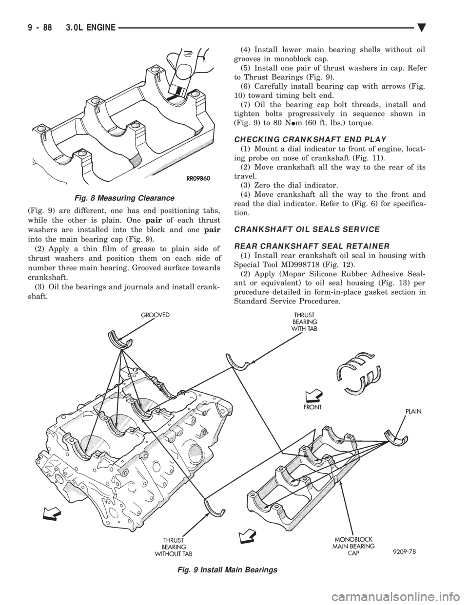
(Fig. 9) are different, one has end positioning tabs,
while the other is plain. One pairof each thrust
washers are installed into the block and one pair
into the main bearing cap (Fig. 9). (2) Apply a thin film of grease to plain side of
thrust washers and position them on each side of
number three main bearing. Grooved surface towards
crankshaft. (3) Oil the bearings and journals and install crank-
shaft. (4) Install lower main bearing shells without oil
grooves in monoblock cap. (5) Install one pair of thrust washers in cap. Refer
to Thrust Bearings (Fig. 9). (6) Carefully install bearing cap with arrows (Fig.
10) toward timing belt end. (7) Oil the bearing cap bolt threads, install and
tighten bolts progressively in sequence shown in
(Fig. 9) to 80 N Im (60 ft. lbs.) torque.
CHECKING CRANKSHAFT END PLAY
(1) Mount a dial indicator to front of engine, locat-
ing probe on nose of crankshaft (Fig. 11). (2) Move crankshaft all the way to the rear of its
travel. (3) Zero the dial indicator.
(4) Move crankshaft all the way to the front and
read the dial indicator. Refer to (Fig. 6) for specifica-
tion.
CRANKSHAFT OIL SEALS SERVICE
REAR CRANKSHAFT SEAL RETAINER
(1) Install rear crankshaft oil seal in housing with
Special Tool MD998718 (Fig. 12). (2) Apply (Mopar Silicone Rubber Adhesive Seal-
ant or equivalent) to oil seal housing (Fig. 13) per
procedure detailed in form-in-place gasket section in
Standard Service Procedures.
Fig. 9 Install Main Bearings
Fig. 8 Measuring Clearance
9 - 88 3.0L ENGINE Ä
Page 1671 of 2438
(3) Before removing valves, remove any burrs
from valve stem lock grooves to prevent damage
to the valve guides. Identify valves to insure instal-
lation in original location.
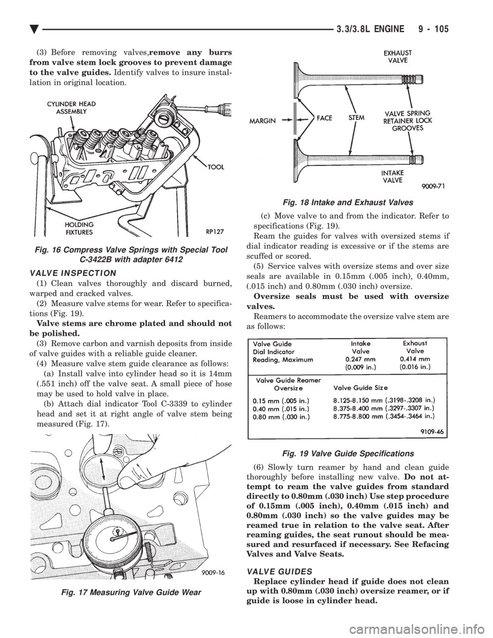
VALVE INSPECTION
(1) Clean valves thoroughly and discard burned,
warped and cracked valves. (2) Measure valve stems for wear. Refer to specifica-
tions (Fig. 19). Valve stems are chrome plated and should not
be polished. (3) Remove carbon and varnish deposits from inside
of valve guides with a reliable guide cleaner. (4) Measure valve stem guide clearance as follows:(a) Install valve into cylinder head so it is 14mm
(.551 inch) off the valve seat. A small piece of hose
may be used to hold valve in place. (b) Attach dial indicator Tool C-3339 to cylinder
head and set it at right angle of valve stem being
measured (Fig. 17). (c) Move valve to and from the indicator. Refer to
specifications (Fig. 19).
Ream the guides for valves with oversized stems if
dial indicator reading is excessive or if the stems are
scuffed or scored. (5) Service valves with oversize stems and over size
seals are available in 0.15mm (.005 inch), 0.40mm,
(.015 inch) and 0.80mm (.030 inch) oversize. Oversize seals must be used with oversize
valves. Reamers to accommodate the oversize valve stem are
as follows:
(6) Slowly turn reamer by hand and clean guide
thoroughly before installing new valve. Do not at-
tempt to ream the valve guides from standard
directly to 0.80mm (.030 inch) Use step procedure
of 0.15mm (.005 inch), 0.40mm (.015 inch) and
0.80mm (.030 inch) so the valve guides may be
reamed true in relation to the valve seat. After
reaming guides, the seat runout should be mea-
sured and resurfaced if necessary. See Refacing
Valves and Valve Seats.
VALVE GUIDES
Replace cylinder head if guide does not clean
up with 0.80mm (.030 inch) oversize reamer, or if
guide is loose in cylinder head.
Fig. 18 Intake and Exhaust Valves
Fig. 19 Valve Guide Specifications
Fig. 16 Compress Valve Springs with Special Tool C-3422B with adapter 6412
Fig. 17 Measuring Valve Guide Wear
Ä 3.3/3.8L ENGINE 9 - 105
Page 1770 of 2438
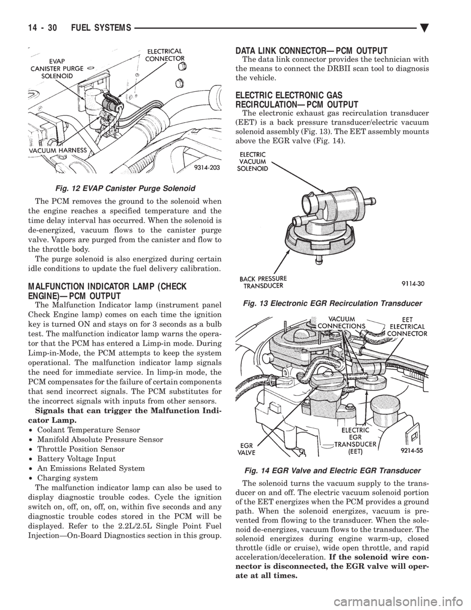
The PCM removes the ground to the solenoid when
the engine reaches a specified temperature and the
time delay interval has occurred. When the solenoid is
de-energized, vacuum flows to the canister purge
valve. Vapors are purged from the canister and flow to
the throttle body. The purge solenoid is also energized during certain
idle conditions to update the fuel delivery calibration.
MALFUNCTION INDICATOR LAMP (CHECK
ENGINE)ÐPCM OUTPUT
The Malfunction Indicator lamp (instrument panel
Check Engine lamp) comes on each time the ignition
key is turned ON and stays on for 3 seconds as a bulb
test. The malfunction indicator lamp warns the opera-
tor that the PCM has entered a Limp-in mode. During
Limp-in-Mode, the PCM attempts to keep the system
operational. The malfunction indicator lamp signals
the need for immediate service. In limp-in mode, the
PCM compensates for the failure of certain components
that send incorrect signals. The PCM substitutes for
the incorrect signals with inputs from other sensors. Signals that can trigger the Malfunction Indi-
cator Lamp.
² Coolant Temperature Sensor
² Manifold Absolute Pressure Sensor
² Throttle Position Sensor
² Battery Voltage Input
² An Emissions Related System
² Charging system
The malfunction indicator lamp can also be used to
display diagnostic trouble codes. Cycle the ignition
switch on, off, on, off, on, within five seconds and any
diagnostic trouble codes stored in the PCM will be
displayed. Refer to the 2.2L/2.5L Single Point Fuel
InjectionÐOn-Board Diagnostics section in this group.
DATA LINK CONNECTORÐPCM OUTPUT
The data link connector provides the technician with
the means to connect the DRBII scan tool to diagnosis
the vehicle.
ELECTRIC ELECTRONIC GAS
RECIRCULATIONÐPCM OUTPUT
The electronic exhaust gas recirculation transducer
(EET) is a back pressure transducer/electric vacuum
solenoid assembly (Fig. 13). The EET assembly mounts
above the EGR valve (Fig. 14).
The solenoid turns the vacuum supply to the trans-
ducer on and off. The electric vacuum solenoid portion
of the EET energizes when the PCM provides a ground
path. When the solenoid energizes, vacuum is pre-
vented from flowing to the transducer. When the sole-
noid de-energizes, vacuum flows to the transducer. The
solenoid energizes during engine warm-up, closed
throttle (idle or cruise), wide open throttle, and rapid
acceleration/deceleration. If the solenoid wire con-
nector is disconnected, the EGR valve will oper-
ate at all times.
Fig. 12 EVAP Canister Purge Solenoid
Fig. 13 Electronic EGR Recirculation Transducer
Fig. 14 EGR Valve and Electric EGR Transducer
14 - 30 FUEL SYSTEMS Ä
Page 1802 of 2438
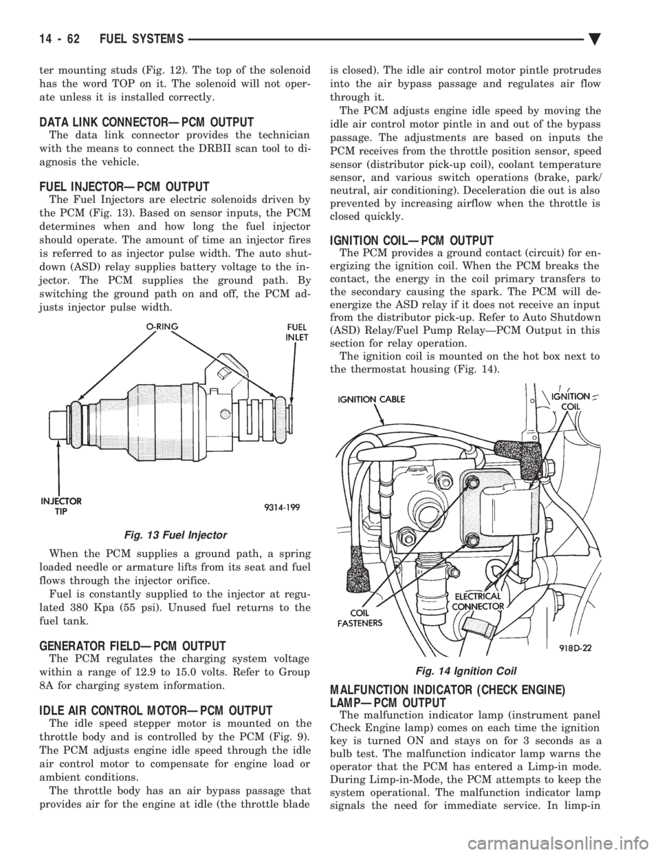
ter mounting studs (Fig. 12). The top of the solenoid
has the word TOP on it. The solenoid will not oper-
ate unless it is installed correctly.
DATA LINK CONNECTORÐPCM OUTPUT
The data link connector provides the technician
with the means to connect the DRBII scan tool to di-
agnosis the vehicle.
FUEL INJECTORÐPCM OUTPUT
The Fuel Injectors are electric solenoids driven by
the PCM (Fig. 13). Based on sensor inputs, the PCM
determines when and how long the fuel injector
should operate. The amount of time an injector fires
is referred to as injector pulse width. The auto shut-
down (ASD) relay supplies battery voltage to the in-
jector. The PCM supplies the ground path. By
switching the ground path on and off, the PCM ad-
justs injector pulse width.
When the PCM supplies a ground path, a spring
loaded needle or armature lifts from its seat and fuel
flows through the injector orifice. Fuel is constantly supplied to the injector at regu-
lated 380 Kpa (55 psi). Unused fuel returns to the
fuel tank.
GENERATOR FIELDÐPCM OUTPUT
The PCM regulates the charging system voltage
within a range of 12.9 to 15.0 volts. Refer to Group
8A for charging system information.
IDLE AIR CONTROL MOTORÐPCM OUTPUT
The idle speed stepper motor is mounted on the
throttle body and is controlled by the PCM (Fig. 9).
The PCM adjusts engine idle speed through the idle
air control motor to compensate for engine load or
ambient conditions. The throttle body has an air bypass passage that
provides air for the engine at idle (the throttle blade is closed). The idle air control motor pintle protrudes
into the air bypass passage and regulates air flow
through it. The PCM adjusts engine idle speed by moving the
idle air control motor pintle in and out of the bypass
passage. The adjustments are based on inputs the
PCM receives from the throttle position sensor, speed
sensor (distributor pick-up coil), coolant temperature
sensor, and various switch operations (brake, park/
neutral, air conditioning). Deceleration die out is also
prevented by increasing airflow when the throttle is
closed quickly.
IGNITION COILÐPCM OUTPUT
The PCM provides a ground contact (circuit) for en-
ergizing the ignition coil. When the PCM breaks the
contact, the energy in the coil primary transfers to
the secondary causing the spark. The PCM will de-
energize the ASD relay if it does not receive an input
from the distributor pick-up. Refer to Auto Shutdown
(ASD) Relay/Fuel Pump RelayÐPCM Output in this
section for relay operation. The ignition coil is mounted on the hot box next to
the thermostat housing (Fig. 14).
MALFUNCTION INDICATOR (CHECK ENGINE)
LAMPÐPCM OUTPUT
The malfunction indicator lamp (instrument panel
Check Engine lamp) comes on each time the ignition
key is turned ON and stays on for 3 seconds as a
bulb test. The malfunction indicator lamp warns the
operator that the PCM has entered a Limp-in mode.
During Limp-in-Mode, the PCM attempts to keep the
system operational. The malfunction indicator lamp
signals the need for immediate service. In limp-in
Fig. 13 Fuel Injector
Fig. 14 Ignition Coil
14 - 62 FUEL SYSTEMS Ä
Page 1830 of 2438
sition, the PCM monitors the crankshaft position and
camshaft position sensor signals to determine engine
speed and ignition timing (coil dwell). If the PCM
does not receive the crankshaft position sensor and
camshaft position sensor signals when the ignition
switch is in the Run position, it de-energizes both re-
lays. When the relays are de-energized, battery volt-
age is not supplied to the fuel injector, ignition coil,
fuel pump and oxygen sensor heating element. The ASD relay and fuel pump relay are located in
the power distribution center (Fig. 16).
IDLE AIR CONTROL MOTORÐPCM OUTPUT
The idle air control motor is mounted on the throt-
tle body (Fig. 14). The PCM operates the motor. The
PCM adjusts engine idle speed through the idle air
control motor to compensate for engine load or ambi-
ent conditions. The throttle body has an air bypass passage that
provides air for the engine at idle (the throttle blade
is closed). The idle air control motor pintle protrudes
into the air bypass passage and regulates air flow
through it. The PCM adjusts engine idle speed by moving the
idle air control motor pintle in and out of the bypass
passage. The adjustments are based on inputs the
PCM receives. The inputs are from the throttle posi-
tion sensor, camshaft position sensor, crankshaft po-
sition sensor, coolant temperature sensor, and
various switch operations (brake and air condition-
ing). Deceleration die out is also prevented by in-
creasing airflow when the throttle is closed quickly
after a driving (speed) condition.
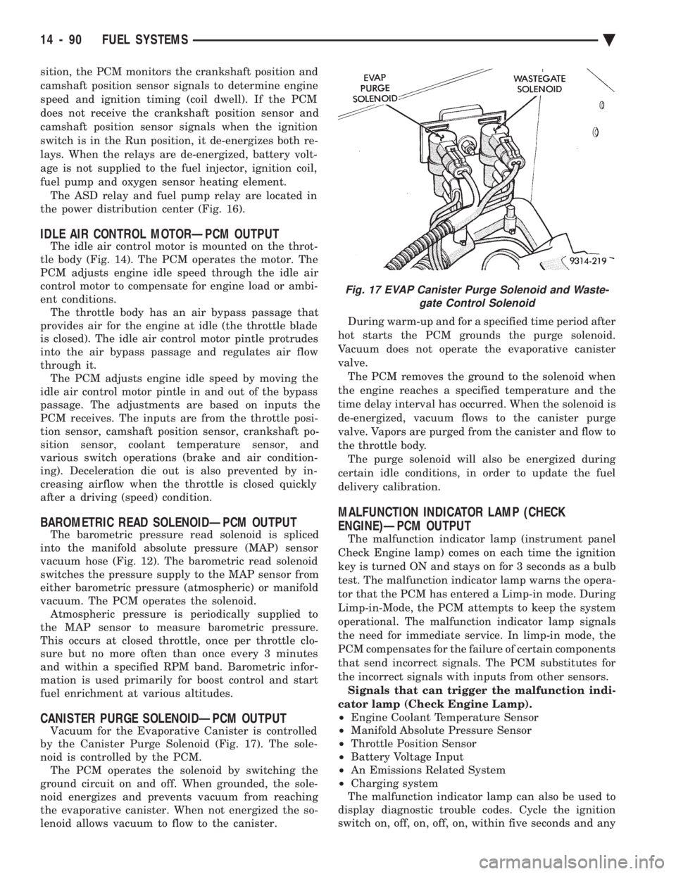
BAROMETRIC READ SOLENOIDÐPCM OUTPUT
The barometric pressure read solenoid is spliced
into the manifold absolute pressure (MAP) sensor
vacuum hose (Fig. 12). The barometric read solenoid
switches the pressure supply to the MAP sensor from
either barometric pressure (atmospheric) or manifold
vacuum. The PCM operates the solenoid. Atmospheric pressure is periodically supplied to
the MAP sensor to measure barometric pressure.
This occurs at closed throttle, once per throttle clo-
sure but no more often than once every 3 minutes
and within a specified RPM band. Barometric infor-
mation is used primarily for boost control and start
fuel enrichment at various altitudes.
CANISTER PURGE SOLENOIDÐPCM OUTPUT
Vacuum for the Evaporative Canister is controlled
by the Canister Purge Solenoid (Fig. 17). The sole-
noid is controlled by the PCM. The PCM operates the solenoid by switching the
ground circuit on and off. When grounded, the sole-
noid energizes and prevents vacuum from reaching
the evaporative canister. When not energized the so-
lenoid allows vacuum to flow to the canister. During warm-up and for a specified time period after
hot starts the PCM grounds the purge solenoid.
Vacuum does not operate the evaporative canister
valve. The PCM removes the ground to the solenoid when
the engine reaches a specified temperature and the
time delay interval has occurred. When the solenoid is
de-energized, vacuum flows to the canister purge
valve. Vapors are purged from the canister and flow to
the throttle body. The purge solenoid will also be energized during
certain idle conditions, in order to update the fuel
delivery calibration.
MALFUNCTION INDICATOR LAMP (CHECK
ENGINE)ÐPCM OUTPUT
The malfunction indicator lamp (instrument panel
Check Engine lamp) comes on each time the ignition
key is turned ON and stays on for 3 seconds as a bulb
test. The malfunction indicator lamp warns the opera-
tor that the PCM has entered a Limp-in mode. During
Limp-in-Mode, the PCM attempts to keep the system
operational. The malfunction indicator lamp signals
the need for immediate service. In limp-in mode, the
PCM compensates for the failure of certain components
that send incorrect signals. The PCM substitutes for
the incorrect signals with inputs from other sensors. Signals that can trigger the malfunction indi-
cator lamp (Check Engine Lamp).
² Engine Coolant Temperature Sensor
² Manifold Absolute Pressure Sensor
² Throttle Position Sensor
² Battery Voltage Input
² An Emissions Related System
² Charging system
The malfunction indicator lamp can also be used to
display diagnostic trouble codes. Cycle the ignition
switch on, off, on, off, on, within five seconds and any
Fig. 17 EVAP Canister Purge Solenoid and Waste- gate Control Solenoid
14 - 90 FUEL SYSTEMS Ä
Page 1860 of 2438
MALFUNCTION INDICATOR LAMP (CHECK ENGINE
LAMP)ÐPCM OUTPUT
The malfunction indicator lamp (instrument panel
Check Engine lamp) comes on each time the ignition
key is turned ON and stays on for 3 seconds as a bulb
test. The malfunction indicator lamp warns the opera-
tor that the PCM has entered a Limp-in mode. During
Limp-in Mode, the PCM attempts to keep the system
operational. The malfunction indicator lamp signals
the need for immediate service. In limp-in mode, the
PCM compensates for the failure of certain components
that send incorrect signals. The PCM substitutes for
the incorrect signals with inputs from other sensors. Signals that can trigger the malfunction indi-
cator lamp (Check Engine Lamp).
² Engine Coolant Temperature Sensor
² Manifold Absolute Pressure Sensor
² Throttle Position Sensor
² Battery Voltage Input
² An Emission Related System (California vehicles)
² Charging system
The malfunction indicator lamp displays diagnostic
trouble codes. Cycle the ignition switch on, off, on, off,
on, within five seconds to display any diagnostic
trouble codes stored in the PCM. Refer to the 3.0L
Multi-Port Fuel InjectionÐOn-Board Diagnostics sec-
tion of this Group for Diagnostic trouble code Descrip-
tions.
DATA LINK CONNECTORÐPCM OUTPUT
The data link connector provides the technician with
the means to connect the DRBII scan tool to diagnosis
the vehicle.
TRANSAXLE CONTROL MODULEÐPCM OUTPUT
The PCM supplies the following information to the
electronic automatic transaxle control module through
the CCD Bus:
² battery temperature ²
brake switch input
² engine coolant temperature
² manifold absolute pressure (MAP)
² speed control information
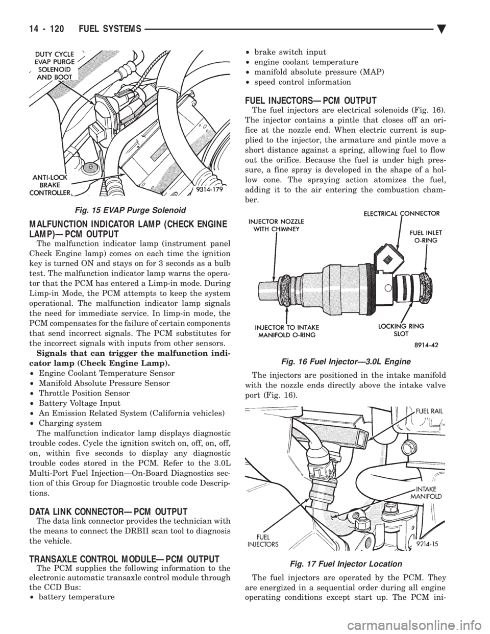
FUEL INJECTORSÐPCM OUTPUT
The fuel injectors are electrical solenoids (Fig. 16).
The injector contains a pintle that closes off an ori-
fice at the nozzle end. When electric current is sup-
plied to the injector, the armature and pintle move a
short distance against a spring, allowing fuel to flow
out the orifice. Because the fuel is under high pres-
sure, a fine spray is developed in the shape of a hol-
low cone. The spraying action atomizes the fuel,
adding it to the air entering the combustion cham-
ber.
The injectors are positioned in the intake manifold
with the nozzle ends directly above the intake valve
port (Fig. 16).
The fuel injectors are operated by the PCM. They
are energized in a sequential order during all engine
operating conditions except start up. The PCM ini-
Fig. 16 Fuel InjectorÐ3.0L Engine
Fig. 17 Fuel Injector Location
Fig. 15 EVAP Purge Solenoid
14 - 120 FUEL SYSTEMS Ä