1993 CHEVROLET PLYMOUTH ACCLAIM oil temperature
[x] Cancel search: oil temperaturePage 37 of 2438
LUBRICATION AND MAINTENANCE
CONTENTS
page page
CHASSIS AND BODY .................... 19
DRIVETRAIN ........................... 16 ENGINE
................................ 8
GENERAL INFORMATION .................. 1
GENERAL INFORMATION INDEX
page page
Classification of Lubricants .................. 1
Fluid Capacities .......................... 4
Fuel Usage .............................. 1
Hoisting Recommendations .................. 5
Introduction .............................. 1 Jump Starting Procedure
.................... 4
Parts and Lubricant Recommendations ......... 1
Parts Requiring No Lubrication ............... 4
Severe Service ........................... 1
Towing Recommendations ................... 7
INTRODUCTION
Chrysler Corporation has compiled recommended
lubrication and maintenance schedules and proce-
dures to help reduce premature wear or failure over
a broad range of operating conditions. When select-
ing the proper maintenance schedule, the climate
and operating conditions must be considered. A vehi-
cle subjected to severe usage requires service more
frequently than a vehicle used for general transpor-
tation.
PARTS AND LUBRICANT RECOMMENDATIONS
When service is required, Chrysler Corporation rec-
ommends that only Mopar tbrand parts, lubricants
and chemicals be used. Mopar tprovides the best en-
gineered products for servicing Chrysler Corporation
vehicles.
SEVERE SERVICE
If a vehicle is operated under any of the following
conditions, it is considered severe service.
² Extremely dusty areas.
² 50% or more of vehicle operation in 32ÉC (90ÉF) or
higher temperatures.
² Prolonged idling ( such as, vehicle operation in
stop and go traffic).
² Frequent short running periods. Not allowing en-
gine to warm to operating temperatures.
² Police or taxi usage.
FUEL USAGE
All Chrysler Corporation engines require the use of
unleaded fuel to reduce exhaust emissions. Use fuel
with a minimum octane rating of 87,(R + M)/2. See
Engine section of this group for Fuel Recommenda-
tions.
CLASSIFICATION OF LUBRICANTS
Only lubricants that are endorsed by the following
organizations standards should be used to service a
Chrysler Corporation vehicle.
² Society of Automotive Engineers (SAE)
² American Petroleum Institute (API)
² National Lubricating Grease Institute (NLGI)
ENGINE OIL
SAE GRADE RATING INDICATES ENGINE OIL VISCOSITY
² SAE 30 = single grade engine oil.
² SAE 5W-30 = multiple grade engine oil.
API QUALITY CLASSIFICATION.
² SG service engine oil is a high quality crankcase
lubricant designed for use in all naturally aspirated
engines.
² SG/CD service engine oil is a high quality crank-
case lubricant designed for use in most naturally as-
pirated and turbocharged gasoline or diesel engines.
GEAR LUBRICANTS
SAE ratings also apply to multiple grade gear lu-
bricants. In addition, API classification defines the
lubricants usage.
Ä LUBRICATION AND MAINTENANCE 0 - 1
Page 44 of 2438
ENGINE INDEX
page page
Engine Oil Filter .......................... 9
Battery ................................ 15
Crankcase Ventilation System ............... 13
Drive Belts ............................. 14
Emission Control System ................... 14
Engine Air Cleaner ....................... 11
Engine Cooling System .................... 10 Engine Oil
............................... 8
Frequency of Engine Oil and Filter Changes ..... 8
Fuel Filter .............................. 14
Fuel Recommendations .................... 14
Ignition Cables, Distributor Cap, and Rotor ..... 14
Rubber and Plastic Component Inspection ...... 15
Spark Plugs ............................ 14
FREQUENCY OF ENGINE OIL AND FILTER
CHANGES
ENGINE OIL
Road conditions as well as your kind of driving af-
fect the interval at which your oil should be changed.
Check the following to determine if any apply to you:
² Frequent short trip driving less than 8 kilometers
(5 miles)
² Frequent driving in dusty conditions
² Frequent trailer towing
² Extensive idling (such as vehicle operation in stop
and go traffic)
² More than 50% of your driving is at sustained
high speeds during hot weather, above 32ÉC (90ÉF) If any of these apply to you then change your en-
gine oil every 4 800 kilometers (3,000 miles) or 3
months, whichever comes first. If none of these apply to you then change your oil
every 12 000 kilometers (7,500 miles) or 6 months,
whichever comes first. If none of these apply and the vehicle is in com-
mercial type service such as, Police, Taxi or Limou-
sine and principally used for highway driving of 40
kilometers (25 miles) or more between stations, the
engine oil should be changed every 8 000 kilometers
(5,000 miles) or 6 months, whichever comes first.
FLEXIBLE FUEL VEHICLES
Flexible fuel is corrosive and contributes to engine
oil contamination. When flexible fuel is being used,
the engine oil should be changed every 8 000 kilome-
ters (5,000 miles) or 6 months, whichever comes first.
OIL FILTER
The engine oil filter should be replaced with a new
filter at every second oil change.
ENGINE OIL
WARNING: NEW OR USED ENGINE OIL CAN BE IR-
RITATING TO THE SKIN. AVOID PROLONGED OR
REPEATED SKIN CONTACT WITH ENGINE OIL.
CONTAMINANTS IN USED ENGINE OIL, CAUSED
BY INTERNAL COMBUSTION, CAN BE HAZARDOUS TO YOUR HEALTH. THOROUGHLY WASH EX-
POSED SKIN WITH SOAP AND WATER. DO NOT WASH SKIN WITH GASOLINE, DIESEL
FUEL, THINNER, OR SOLVENTS, HEALTH PROB-
LEMS CAN RESULT. DO NOT POLLUTE, DISPOSE OF USED ENGINE
OIL PROPERLY. CONTACT YOUR DEALER OR
GOVERNMENT AGENCY FOR LOCATION OF COL-
LECTION CENTER IN YOUR AREA.
BREAK-IN PERIOD
CAUTION: Wide open throttle operation in low
gears, before engine break-in period is complete,
can damage engine.
On a Chrysler Corporation vehicle an extended
break-in period is not required. Driving speeds of not
over 80-90 km/h (50-55 mph) for the first 100 km (60
miles) is recommended. Hard acceleration and high
engine rpm in lower gears should be avoided.
SELECTING ENGINE OIL
CAUTION: Do not use non-detergent or straight
mineral oil when adding or changing crankcase lu-
bricant. Engine or Turbocharger failure can result.
The factory fill engine oil is a high quality, energy
conserving, crankcase lubricant. The Recommended
SAE Viscosity Grades chart defines the viscosity
grades that must be used based on temperature in
the region where vehicle is operated and optional
equipment.
NON-FLEXIBLE FUEL VEHICLES Chrysler Corporation recommends that Mopar mo-
tor oil, or equivalent, be used when adding or chang-
ing crankcase lubricant. The API symbol (Fig. 1) on
the container indicates the viscosity grade, quality
and fuel economy ratings of the lubricant it contains.
Use ENERGY CONSERVING II motor oil with API
SERVICE SG or SG/CD classification.
0 - 8 LUBRICATION AND MAINTENANCE Ä
Page 46 of 2438
ENGINE COOLING SYSTEM
WARNINGS AND PRECAUTIONS
WARNING: ANTIFREEZE IS AN ETHYLENE GLYCOL
BASE COOLANT AND IS HARMFUL IF SWAL-
LOWED OR INHALED. IF SWALLOWED, DRINK
TWO GLASSES OF WATER AND INDUCE VOMIT-
ING. IF INHALED, MOVE TO FRESH AIR AREA.
SEEK MEDICAL ATTENTION IMMEDIATELY. DO
NOT STORE IN OPEN OR UNMARKED CONTAIN-
ERS. WASH SKIN AND CLOTHING THOROUGHLY
AFTER COMING IN CONTACT WITH ETHYLENE
GLYCOL. KEEP OUT OF REACH OF CHILDREN. DISPOSE OF GLYCOL BASE COOLANT PROP-
ERLY, CONTACT YOUR DEALER OR GOVERNMENT
AGENCY FOR LOCATION OF COLLECTION CEN-
TER IN YOUR AREA. DO NOT OPEN A COOLING SYSTEM WHEN THE
ENGINE IS AT RUNNING TEMPERATURE, PER-
SONAL INJURY CAN RESULT. AVOID RADIATOR COOLING FAN WHEN ENGINE
COMPARTMENT RELATED SERVICE IS PER-
FORMED, PERSONAL INJURY CAN RESULT.
CAUTION: Do not use straight antifreeze as engine
coolant, inadequate engine running temperatures
can result. Do not operate vehicle without proper concentra-
tion of recommended ethylene glycol coolant, high
running temperatures and cooling system corrosion
can result.
The engine cooling system will develop internal
pressure of 97 to 123 kPa (14 to 18 psi) at normal op-
erating temperature. Allow the vehicle approxi-
mately one half hour to cool off before opening the
cooling system. As an indicator of pressure, squeeze
the upper radiator hose between index finger and
thumb. If it collapses with little effort the system
would have low internal pressure and should be safe
to open to the first safety notch of the radiator cap.
Refer to Group 7, Cooling System.
COOLING SYSTEM INSPECTION
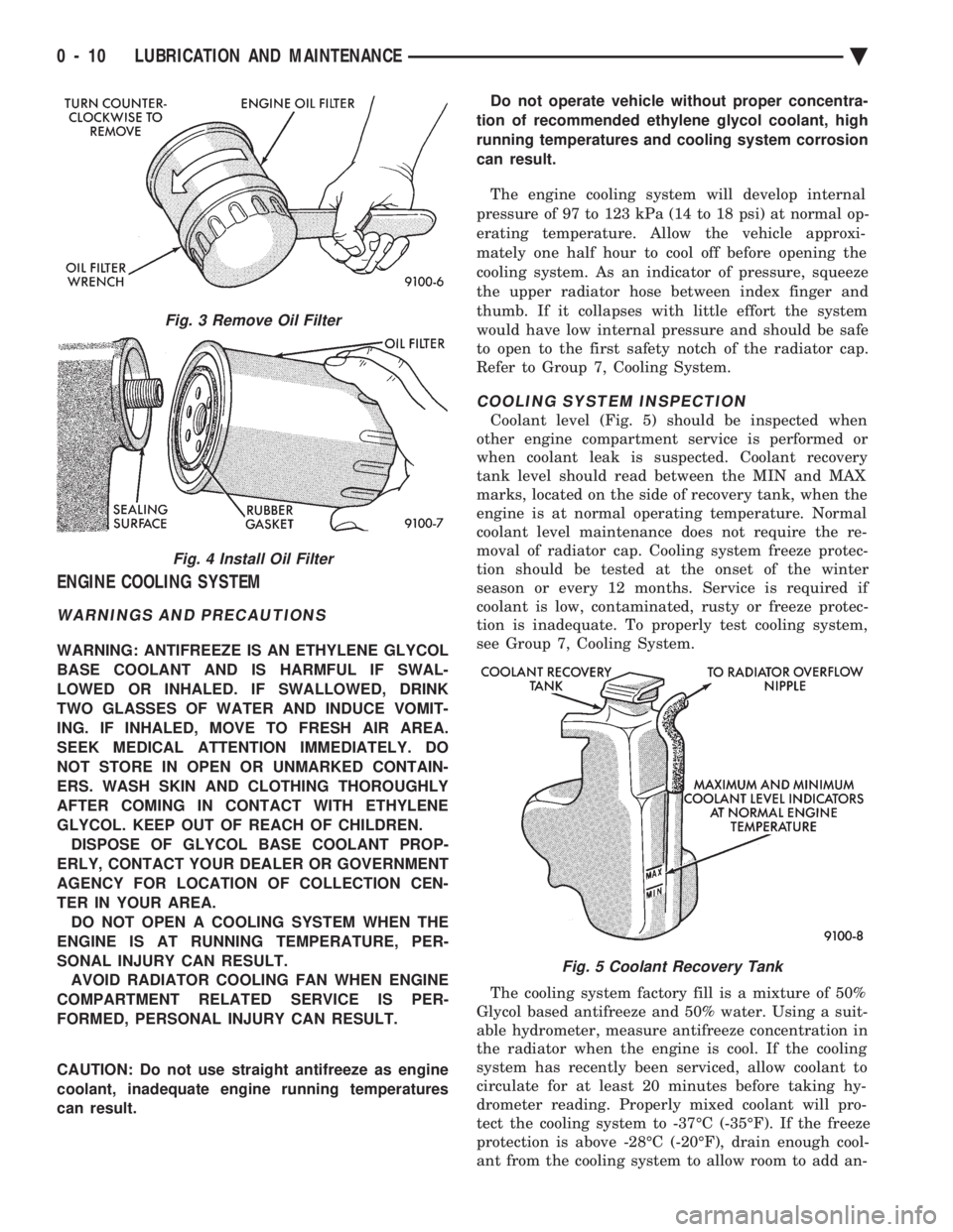
Coolant level (Fig. 5) should be inspected when
other engine compartment service is performed or
when coolant leak is suspected. Coolant recovery
tank level should read between the MIN and MAX
marks, located on the side of recovery tank, when the
engine is at normal operating temperature. Normal
coolant level maintenance does not require the re-
moval of radiator cap. Cooling system freeze protec-
tion should be tested at the onset of the winter
season or every 12 months. Service is required if
coolant is low, contaminated, rusty or freeze protec-
tion is inadequate. To properly test cooling system,
see Group 7, Cooling System.
The cooling system factory fill is a mixture of 50%
Glycol based antifreeze and 50% water. Using a suit-
able hydrometer, measure antifreeze concentration in
the radiator when the engine is cool. If the cooling
system has recently been serviced, allow coolant to
circulate for at least 20 minutes before taking hy-
drometer reading. Properly mixed coolant will pro-
tect the cooling system to -37ÉC (-35ÉF). If the freeze
protection is above -28ÉC (-20ÉF), drain enough cool-
ant from the cooling system to allow room to add an-
Fig. 3 Remove Oil Filter
Fig. 4 Install Oil Filter
Fig. 5 Coolant Recovery Tank
0 - 10 LUBRICATION AND MAINTENANCE Ä
Page 56 of 2438

The power steering pump drive belt should be in-
spected at the time and distance interval described in
the Lubrication and Maintenance Schedules. Refer to
the General Information section of this group.
POWER STEERING FLUID INSPECTION
WARNING: ENGINE MUST NOT BE RUNNING WHEN
INSPECTING POWER STEERING FLUID LEVEL,
PERSONAL INJURY CAN RESULT.
CAUTION: Do not over fill power steering reservoir
when adding fluid, seal damage and leakage can re-
sult.
TO INSPECT FLUID LEVEL:
(1) Position vehicle on a level surface with engine
at normal running temperature. (2) Turn OFF engine and remove ignition key.
(3) Using a wiping cloth, clean oil and dirt residue
from around power steering reservoir cap. (4) Remove reservoir cap or dipstick and wipe off
fluid. (5) Install cap or dipstick.
(6) Remove cap or dipstick. Holding handle or cap
above tip of dipstick, read fluid level (Fig. 4, 5, or 6).
Add fluid if reading is below cold level mark on dip-
stick.
REAR WHEEL BEARINGS
INSPECTION
The rear wheel bearings should be packed with
new lubricant at the distance interval described in the Lubrication and Maintenance Schedules. Refer to
the General Information section of this group. The
bearings should be inspected for contamination and
wear before they are cleaned. Slight discoloration of
bearing rollers and race cup is normal. If metal
Fig. 3 Ball Joint Lubrication
Fig. 4 Power Steering Reservoir DipstickÐ2.2L or 2.5L Engine
Fig. 5 Power Steering Reservoir DipstickÐ3.0L Engine
Fig. 6 Power Steering Reservoir DipstickÐ3.3L or3.8L Engine
0 - 20 LUBRICATION AND MAINTENANCE Ä
Page 220 of 2438

(7) Unfasten brackets on steel heater water line at
dash panel and left frame rail. On Manual Transmis-
sion vehicles, unfasten clutch cable bracket at shock
tower and move aside. (8) Slide the power brake unit up and to the left
(mounting holes are slotted) on the dash panel, then
tilt inboard and up to remove.
CAUTION: Do not attempt to disassemble power
brake unit as this booster is serviced ONLY as a
complete assembly.
INSTALL (1) Position power brake booster onto dash panel.
(2) Install and tighten the 4 power brake booster to
dash panel mounting nuts (Fig. 5) to 29 N Im (250 in.
lbs.) torque. (3) Install steel heater water line and clutch cable
bracket, if so equipped. (4) Carefully position master cylinder on power
brake unit. (5) Install and tighten the 2 master cylinder to
power booster mounting nuts (Fig. 4) to 29 N Im (250
in. lbs.) torque. (6) Connect vacuum hose onto the check valve, lo-
cated on the power brake unit. (7) Using lubriplate, or equivalent, coat the bearing
surface of pedal pin (Fig. 5). (8) Connect power brake booster input rod to brake
pedal pin and install a NEW retainer clip. Use only a
new retainer clip DO NOT USE the old clip. (9) Check stop light operation.
WHEEL BEARINGS
FRONT WHEEL BEARINGS
Front wheel drive vehicles are equipped with per-
manently sealed front wheel bearings. There is no
periodic lubrication or maintenance recommended for
these units. However if during servicing of the brake
system, service to the front wheel bearing is required
refer to Group 2, Suspension in this service manual.
REAR WHEEL BEARINGS
NORMAL SERVICE
The lubricant in the rear wheel bearings should be
inspected whenever the hubs are removed to inspect
or service the brake system. Or at least every 30,000
miles (48,000 km). The bearings should be cleaned
and repacked with a High Temperature Multipurpose
E.P. Grease whenever the disc brake rotors are re-
surfaced.
INSPECTION
Check lubricant to see that it is adequate in quan-
tity and quality. If the grease is low in quantity, con-
tains dirt, appears dry or has been contaminated
with water, it will appear milky. The bearings then must be cleaned and repacked.
Do not add grease to
a wheel bearing that already has grease packed
in it. Relubricate completely. Mixing of different
types of greases in wheel bearings should be
avoided since it may result in excessive thinning
and leakage of the grease.
REMOVAL AND INSTALLATION
For the servicing, removal and installation of the
rear wheel bearings follow the procedure listed below. (1) Remove the rear tire and wheel assembly.
(2) On rear disc brake equipped vehicles remove the
caliper and rotor. Support the caliper out of the way.
Do not allow the caliper to hang by the hydraulic
hose. See disc brake section in this group for caliper
removal procedure. (3) Remove grease cap, cotter pin, nut lock, nut,
thrust washer and outer wheel bearing. (4) Carefully slide hub or drum from spindle. Do not
drag inner bearing or grease seal over stub axle
(thread, bearing, and oil seal may be damaged.) Using
an appropriate tool remove the grease seal and inner
bearing from the drum or hub. Discard grease
Fig. 5 Power Brake Booster Mounting
5 - 70 BRAKES Ä
Page 356 of 2438
INSTALLATIONÐ3.3L AND 3.8L ENGINE
Place a new gasket (dipped in water) on the water
box surface, center thermostat into opening in the in-
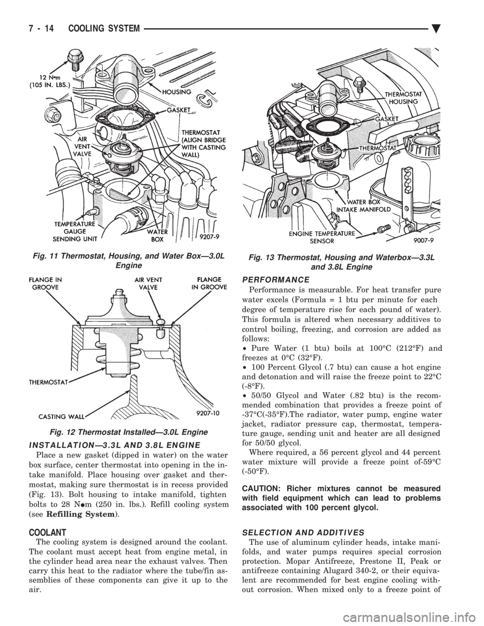
take manifold. Place housing over gasket and ther-
mostat, making sure thermostat is in recess provided
(Fig. 13). Bolt housing to intake manifold, tighten
bolts to 28 N Im (250 in. lbs.). Refill cooling system
(see Refilling System ).
COOLANT
The cooling system is designed around the coolant.
The coolant must accept heat from engine metal, in
the cylinder head area near the exhaust valves. Then
carry this heat to the radiator where the tube/fin as-
semblies of these components can give it up to the
air.
PERFORMANCE
Performance is measurable. For heat transfer pure
water excels (Formul a = 1 btu per minute for each
degree of temperature rise for each pound of water).
This formula is altered when necessary additives to
control boiling, freezing, and corrosion are added as
follows:
² Pure Water (1 btu) boils at 100ÉC (212ÉF) and
freezes at 0ÉC (32ÉF).
² 100 Percent Glycol (.7 btu) can cause a hot engine
and detonation and will raise the freeze point to 22ÉC
(-8ÉF).
² 50/50 Glycol and Water (.82 btu) is the recom-
mended combination that provides a freeze point of
-37ÉC(-35ÉF).The radiator, water pump, engine water
jacket, radiator pressure cap, thermostat, tempera-
ture gauge, sending unit and heater are all designed
for 50/50 glycol. Where required, a 56 percent glycol and 44 percent
water mixture will provide a freeze point of-59ÉC
(-50ÉF).
CAUTION: Richer mixtures cannot be measured
with field equipment which can lead to problems
associated with 100 percent glycol.
SELECTION AND ADDITIVES
The use of aluminum cylinder heads, intake mani-
folds, and water pumps requires special corrosion
protection. Mopar Antifreeze, Prestone II, Peak or
antifreeze containing Alugard 340-2, or their equiva-
lent are recommended for best engine cooling with-
out corrosion. When mixed only to a freeze point of
Fig. 11 Thermostat, Housing, and Water BoxÐ3.0L Engine
Fig. 12 Thermostat InstalledÐ3.0L Engine
Fig. 13 Thermostat, Housing and WaterboxÐ3.3Land 3.8L Engine
7 - 14 COOLING SYSTEM Ä
Page 357 of 2438

-37ÉC (-35ÉF) to -59ÉC (-50ÉF). If it looses color or
becomes contaminated, drain, flush, and replace with
fresh properly mixed solution.
SERVICE
Coolant should be changed at 52,500 miles or three
years, whichever occurs first, then every two years or
30,000 miles.
ROUTINE LEVEL CHECK
Do not remove radiator cap for routine coolant
level inspections. The coolant reserve system provides a quick visual
method for determining the coolant level without re-
moving the radiator cap. Simply observe, with the
engine idling and warmed up to normal operating
temperature, that the level of the coolant in the reserve
tank (Figs. 5 and 6) is between the minimum and
maximum marks.
ADDING ADDITIONAL COOLANT
The radiator cap should not be removed. When
additional coolant is needed to maintain this level, it
should be added to the coolant reserve tank. Use only
50/50 concentration of ethylene glycol type antifreeze
and water.
SERVICE COOLANT LEVEL
The cooling system is closed and designed to main-
tain coolant level to the top of the radiator. When servicing requires a coolant level check in the
radiator, the engine must be offand notunder pres-
sure. Drain several ounces of coolant from the radiator
drain cock while observing the Coolant Recovery Sys-
tem (CRS) Tank. Coolant level in the CRS tank should
drop slightly. Then remove the radiator cap. The radia-
tor should be full to the top. If not, and the coolant level
in the CRS tank is at the MIN mark there is a air leak
in the CRS system. Check hose or hose connections to
the CRS tank, radiator filler neck or the pressure cap
seal to the radiator filler neck for leaks.
LOW COOLANT LEVEL AERATION
Low coolant level in a cross flow radiator will equal-
ize in both tanks with engine off. With engine at
running operating temperature the high pressure inlet
tank runs full and the low pressure outlet tank drops.
If this level drops below the top of the transmission oil
cooler, air will be sucked into the water pump:
² Transmission oil will become hotter.
² High reading shown on the temperature gauge.
² Air in the coolant will also cause loss of flow through
the heater.
² Exhaust gas leaks into the coolant can also cause the
same problems.
DEAERATION
Air can only be removed from the system by gather-
ing under the pressure cap. On the next heat up it will
be pushed past the pressure cap into the CRS tank by
thermal expansion of the coolant. It then escapes to the
atmosphere in the CRS tank and is replaced with solid
coolant on cool down.
COOLING SYSTEM DRAIN, CLEAN, FLUSH AND
REFILL
Drain, flush, and fill the cooling system at the
mileage or time intervals specified in the Maintenance
Schedule in this Group. If the solution is dirty or rusty
or contains a considerable amount of sediment, clean
and flush with a reliable cooling system cleaner. Care
should be taken in disposing of the used engine coolant
from your vehicle. Check governmental regulations for
disposal of used engine coolant.
DRAINING
To drain cooling system move temperature selector
for heater to full heat with engine running (to provide
vacuum for actuation). Without removing radiator
pressure cap and with system not under pres-
sure, Shut engine off and open draincock. The coolant
reserve tank (Fig. 5) should empty first, then remove
radiator pressure cap. (if not, see Testing Cooling
System for leaks). To vent 2.2/2.5L engines remove the
plug above thermostat housing (Fig. 1). For Turbo III
engines remove coolant temperature sensor in the
thermostat housing (Fig. 2). For 3.3L /3.8L engine
remove the engine temperature sending unit (Fig. 3).
Removal of a plug or other component is required
because the thermostat has no air vent and prevents
air flow through it. This allows the coolant to drain
from the engine block.
Fig. 1 Thermostat Housing Drain/Fill PlugÐ2.2/2.5L Engines
Ä COOLING SYSTEM 7 - 15
Page 379 of 2438
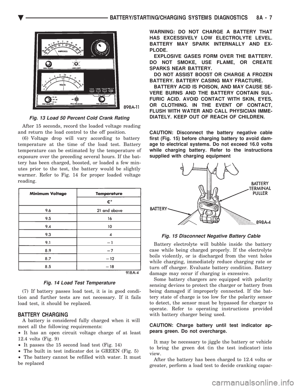
After 15 seconds, record the loaded voltage reading
and return the load control to the off position. (6) Voltage drop will vary according to battery
temperature at the time of the load test. Battery
temperature can be estimated by the temperature of
exposure over the preceding several hours. If the bat-
tery has been charged, boosted, or loaded a few min-
utes prior to the test, the battery would be slightly
warmer. Refer to Fig. 14 for proper loaded voltage
reading.
(7) If battery passes load test, it is in good condi-
tion and further tests are not necessary. If it fails
load test, it should be replaced.
BATTERY CHARGING
A battery is considered fully charged when it will
meet all the following requirements:
² It has an open circuit voltage charge of at least
12.4 volts (Fig. 9)
² It passes the 15 second load test (Fig. 14)
² The built in test indicator dot is GREEN (Fig. 5)
² The battery cannot be refilled with water. It must
be replaced WARNING: DO NOT CHARGE A BATTERY THAT
HAS EXCESSIVELY LOW ELECTROLYTE LEVEL.
BATTERY MAY SPARK INTERNALLY AND EX-
PLODE. EXPLOSIVE GASES FORM OVER THE BATTERY.
DO NOT SMOKE, USE FLAME, OR CREATE
SPARKS NEAR BATTERY. DO NOT ASSIST BOOST OR CHARGE A FROZEN
BATTERY. BATTERY CASING MAY FRACTURE. BATTERY ACID IS POISON, AND MAY CAUSE SE-
VERE BURNS AND THE BATTERY CONTAIN SUL-
FURIC ACID. AVOID CONTACT WITH SKIN, EYES,
OR CLOTHING. IN THE EVENT OF CONTACT,
FLUSH WITH WATER AND CALL PHYSICIAN IMME-
DIATELY. KEEP OUT OF REACH OF CHILDREN.
CAUTION: Disconnect the battery negative cable
first (Fig. 15) before charging battery to avoid dam-
age to electrical systems. Do not exceed 16.0 volts
while charging battery. Refer to the instructions
supplied with charging equipment
Battery electrolyte will bubble inside the battery
case while being charged properly. If the electrolyte
boils violently, or is discharged from the vent holes
while charging, immediately reduce charging rate or
turn off charger. Evaluate battery condition. Battery
damage may occur if charging is excessive. Some battery chargers are equipped with polarity
sensing devices to protect the charger or battery from
being damaged if improperly connected. If the bat-
tery state of charge is too low for the polarity sensor
to detect, the sensor must be bypassed for charger to
operate. Refer to operating instructions provided
with battery charger being used.
CAUTION: Charge battery until test indicator ap-
pears green. Do not overcharge.
It may be necessary to jiggle the battery or vehicle
to bring the green dot (in the test indicator) into
view. After the battery has been charged to 12.4 volts or
greater, perform a load test to decide cranking capac-
Fig. 13 Load 50 Percent Cold Crank Rating
Fig. 14 Load Test Temperature
Fig. 15 Disconnect Negative Battery Cable
Ä BATTERY/STARTING/CHARGING SYSTEMS DIAGNOSTICS 8A - 7