1993 CHEVROLET PLYMOUTH ACCLAIM fascia
[x] Cancel search: fasciaPage 31 of 2438
COMPONENT AND SYSTEM INDEX
Name Group-page Name Group-page
BODY ................................... 23-1
AA-VEHICLE BODY COMPONENT SERVICE .......23-11
AC-VEHICLE BODY COMPONENT SERVICE .......23-37
AG-VEHICLE BODY COMPONENT SERVICE .......23-52
AJ/27-VEHICLE CONVERTIBLE BODY COMPONENT SERVICE ............................ 23-86
AJ-VEHICLE BODY COMPONENT SERVICE .......23-71
AP-VEHICLE BODY COMPONENT SERVICE .......23-97
AY-VEHICLE BODY COMPONENT SERVICE .......23-133
BODY DIAGNOSTIC PROCEDURES .............23-2
GENERAL SERVICE INFORMATION .............23-1
PAINT ................................. 23-4
POWER SUNROOF ........................ 23-6
WINDSHIELD ............................ 23-9
BRAKES ..................................5-1
ANTI-LOCK BRAKE SYSTEMÐBENDIX ANTI-LOCK 10 AC/Y BODY ......................... 5-72
ANTI-LOCK BRAKE SYSTEMÐBENDIX ANTI-LOCK 6 AA,AG,AJ,AP BODY .................... 5-113
BRAKE DISC (ROTOR) ...................... 5-53
BRAKE SUPPORT ASSEMBLY .................5-25
FRONT DISC BRAKES ...................... 5-31
GENERAL INFORMATION .....................5-1
HYDRAULIC SYSTEM CONTROL VALVES .........5-26
KELSEY HAYES DOUBLE PIN FAMILY CALIPER .....5-35
KELSEY HAYES DOUBLE PIN NON-FAMILY CALIPER ............................. 5-38
MASTER CYLINDER ....................... 5-66
PARKING BRAKES ........................ 5-57
POWER BRAKES ......................... 5-68
REAR DISC BRAKES ....................... 5-45
REAR WHEEL DRUM BRAKES ................5-18
SERVICE ADJUSTMENTS .....................5-4
WHEEL BEARINGS ........................ 5-70
WHEEL CYLINDERS ....................... 5-23
COOLING SYSTEM ...........................7-1
ACCESSORY DRIVE BELTS ................... 7-24
ENGINE BLOCK HEATER .................... 7-28
GENERAL INFORMATION .....................7-1
SERVICE PROCEDURES ..................... 7-10
SPECIFICATIONS ......................... 7-29
ENGINE ..................................9-1
2.2/2.5L ENGINES .........................9-8
3.0L ENGINE ............................ 9-66
3.3/3.8L ENGINE ......................... 9-98
STANDARD SERVICE PROCEDURES .............9-1
EXHAUST SYSTEM AND INTAKE MANIFOLD .........11-1
GENERAL INFORMATION .................... 11-1
SERVICE PROCEDURES ..................... 11-4
TORQUE SPECIFICATION ................... 11-25
FRAME AND BUMPERS ....................... 13-1
BUMPER AND FASCIA ...................... 13-1
FRAME ................................ 13-9
HEATING AND AIR CONDITIONING ...............24-1
AUTOMATIC TEMPERATURE CONTROL (ATC) .....24-66 COMPONENT SERVICE PROCEDURES
..........24-47
FIXED DISPLACEMENT COMPRESSORÐMODEL 10PA17............................. 24-24
FIXED DISPLACEMENT COMPRESSORÐMODEL SD709P ............................. 24-38
FIXED DISPLACEMENT COMPRESSORÐMODEL TR105 .............................. 24-32
GENERAL INFORMATION .................... 24-1
HEATER AND A/C PERFORMANCE TESTS .........24-6
REFRIGERANT SERVICE PROCEDURES ..........24-8
VACUUM CONTROL SYSTEM DIAGNOSIS .........24-4
VARIABLE DISPLACEMENT COMPRESSORÐMODEL 6C17 ............................... 24-13
INTRODUCTION .......................... Intro.-1
LUBRICATION AND MAINTENANCE ................0-1
CHASSIS AND BODY ....................... 0-19
DRIVETRAIN ............................ 0-16
ENGINE ................................0-8
GENERAL INFORMATION .....................0-1
MANUAL TRANSAXLE CLUTCH ...................6-1
STEERING ................................ 19-1
ACUSTAR STANDARD AND TILT STEERING COLUMN ............................ 19-28
AUTOMATIC TRANSMISSION SHIFTER/IGNITION INTERLOCK .......................... 19-36
GENERAL INFORMATION .................... 19-1
POWER STEERING GEAR ................... 19-25
POWER STEERING PUMPS ..................19-1
SPECIFICATIONS AND TIGHTENING REFERENCE . . . 19-42
SUSPENSION AND DRIVESHAFTS .................2-1
AUTOMATIC AIR LOAD LEVELING SYSTEM ........2-59
AUTOMATIC AIR SUSPENSION ................2-73
DRIVESHAFTS ........................... 2-25
FRONT SUSPENSION .......................2-2
FRONT SUSPENSION SERVICE PROCEDURES .......2-5
GENERAL INFORMATION .....................2-1
REAR (STUB) AXLE ALIGNMENT ALL MODELS .....2-89
REAR SUSPENSION ....................... 2-50
SPECIFICATIONS ......................... 2-91
TRANSAXLE .............................. 21-85
41TE FOUR SPEED AUTOMATIC TRANSAXLE ......21-85
41TE FOUR SPEED TRANSAXLE HYDRAULIC SCHEMATICS ........................ 21-170
41TE ON-BOARD DIAGNOSTICS .............21-145
A-523, A-543, and A-568 MANUAL TRANSAXLE ....21-1
SPECIFICATIONS ........................ 21-183
THREE SPEED TORQUEFLITE AUTOMATIC TRANSAXLE .......................... 21-35
THREE SPEED TRANSAXLE HYDRAULIC SCHEMATICS ........................ 21-162
WHEELSÐTIRES ........................... 22-1
SPECIFICATIONS ......................... 22-8
TIRE SERVICE PROCEDURES .................22-1
WHEELS SERVICE PROCEDURES ..............22-6
Page 43 of 2438
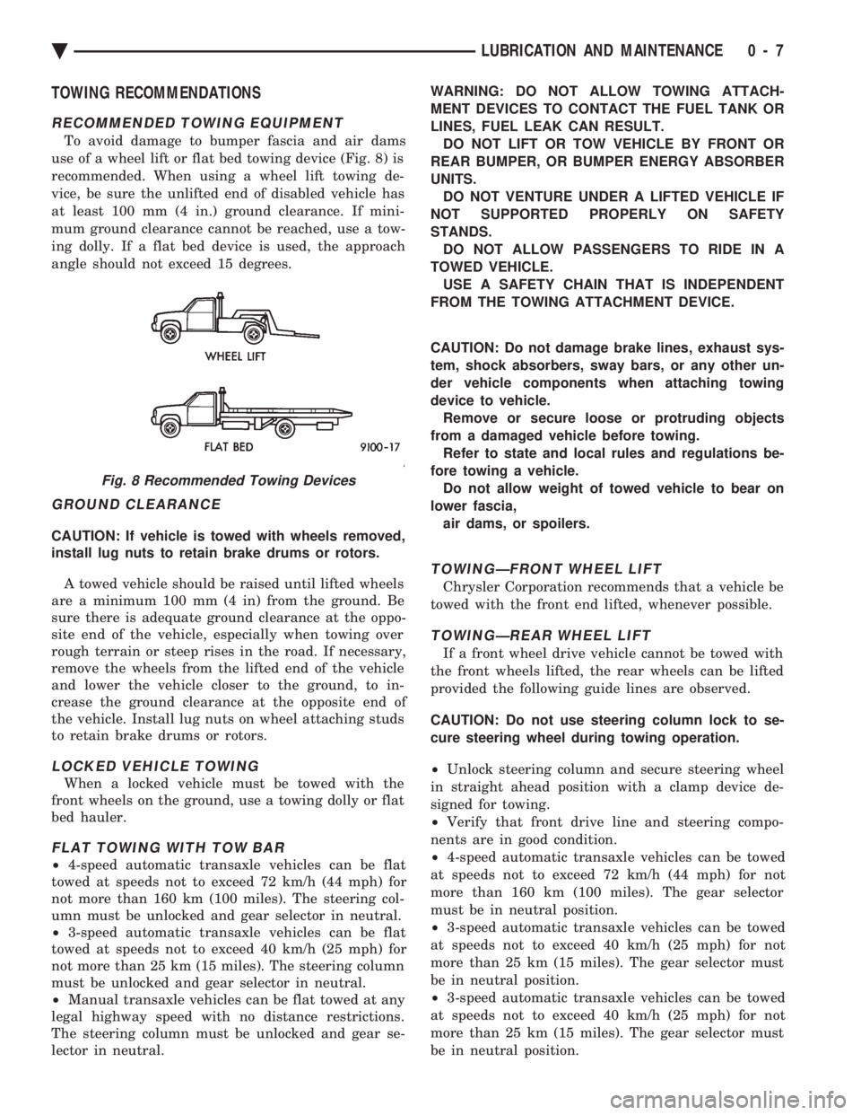
TOWING RECOMMENDATIONS
RECOMMENDED TOWING EQUIPMENT
To avoid damage to bumper fascia and air dams
use of a wheel lift or flat bed towing device (Fig. 8) is
recommended. When using a wheel lift towing de-
vice, be sure the unlifted end of disabled vehicle has
at least 100 mm (4 in.) ground clearance. If mini-
mum ground clearance cannot be reached, use a tow-
ing dolly. If a flat bed device is used, the approach
angle should not exceed 15 degrees.
GROUND CLEARANCE
CAUTION: If vehicle is towed with wheels removed,
install lug nuts to retain brake drums or rotors.
A towed vehicle should be raised until lifted wheels
are a minimum 100 mm (4 in) from the ground. Be
sure there is adequate ground clearance at the oppo-
site end of the vehicle, especially when towing over
rough terrain or steep rises in the road. If necessary,
remove the wheels from the lifted end of the vehicle
and lower the vehicle closer to the ground, to in-
crease the ground clearance at the opposite end of
the vehicle. Install lug nuts on wheel attaching studs
to retain brake drums or rotors.
LOCKED VEHICLE TOWING
When a locked vehicle must be towed with the
front wheels on the ground, use a towing dolly or flat
bed hauler.
FLAT TOWING WITH TOW BAR
² 4-speed automatic transaxle vehicles can be flat
towed at speeds not to exceed 72 km/h (44 mph) for
not more than 160 km (100 miles). The steering col-
umn must be unlocked and gear selector in neutral.
² 3-speed automatic transaxle vehicles can be flat
towed at speeds not to exceed 40 km/h (25 mph) for
not more than 25 km (15 miles). The steering column
must be unlocked and gear selector in neutral.
² Manual transaxle vehicles can be flat towed at any
legal highway speed with no distance restrictions.
The steering column must be unlocked and gear se-
lector in neutral. WARNING: DO NOT ALLOW TOWING ATTACH-
MENT DEVICES TO CONTACT THE FUEL TANK OR
LINES, FUEL LEAK CAN RESULT. DO NOT LIFT OR TOW VEHICLE BY FRONT OR
REAR BUMPER, OR BUMPER ENERGY ABSORBER
UNITS. DO NOT VENTURE UNDER A LIFTED VEHICLE IF
NOT SUPPORTED PROPERLY ON SAFETY
STANDS. DO NOT ALLOW PASSENGERS TO RIDE IN A
TOWED VEHICLE. USE A SAFETY CHAIN THAT IS INDEPENDENT
FROM THE TOWING ATTACHMENT DEVICE.
CAUTION: Do not damage brake lines, exhaust sys-
tem, shock absorbers, sway bars, or any other un-
der vehicle components when attaching towing
device to vehicle. Remove or secure loose or protruding objects
from a damaged vehicle before towing. Refer to state and local rules and regulations be-
fore towing a vehicle. Do not allow weight of towed vehicle to bear on
lower fascia, air dams, or spoilers.
TOWINGÐFRONT WHEEL LIFT
Chrysler Corporation recommends that a vehicle be
towed with the front end lifted, whenever possible.
TOWINGÐREAR WHEEL LIFT
If a front wheel drive vehicle cannot be towed with
the front wheels lifted, the rear wheels can be lifted
provided the following guide lines are observed.
CAUTION: Do not use steering column lock to se-
cure steering wheel during towing operation.
² Unlock steering column and secure steering wheel
in straight ahead position with a clamp device de-
signed for towing.
² Verify that front drive line and steering compo-
nents are in good condition.
² 4-speed automatic transaxle vehicles can be towed
at speeds not to exceed 72 km/h (44 mph) for not
more than 160 km (100 miles). The gear selector
must be in neutral position.
² 3-speed automatic transaxle vehicles can be towed
at speeds not to exceed 40 km/h (25 mph) for not
more than 25 km (15 miles). The gear selector must
be in neutral position.
² 3-speed automatic transaxle vehicles can be towed
at speeds not to exceed 40 km/h (25 mph) for not
more than 25 km (15 miles). The gear selector must
be in neutral position.
Fig. 8 Recommended Towing Devices
Ä LUBRICATION AND MAINTENANCE 0 - 7
Page 422 of 2438

COMPASS MODULE REPLACEMENT
(1) Remove overhead console.
(2) Using a small screwdriver, release the 2 snaps
at rear of compass module. (3) After releasing the 2 snaps, slide compass mod-
ule rearward until free of mounting bar. (4) For installation reverse above procedures.
AMBIENT TEMPERATURE SENSOR
(1) Raise and support vehicle on safety stands.
(2) From behind front bumper fascia, remove screw
attaching sensor to front lower crossmember (Fig. 7). (3) For installation, reverse above procedures.
AC AND AY BODY
INDEX
page page
Ambient Temperature Sensor ............... 12
Automatic Calibration Set Procedure ........... 8
Bezel/Button Switch Removal ............... 10
Bus Accessed Diagnostics .................. 10
Console Removal ........................ 10
Electronic Board Assembly Replacement ....... 10
Electronic Vehicle Information Center (EVIC) Overhead Console ....................... 6 Engine Compartment Node Removal
.......... 12
EVIC Self Check Diagnostics ................ 8
Manual Calibration Set Procedure ............. 8
Map Reading Lamps/Power Sunroof Switch Removal .............................. 11
Overhead Reading/Courtesy Lamp Console ..... 11
Wiring Harness Removal ................... 10
ELECTRONIC VEHICLE INFORMATION CENTER
(EVIC) OVERHEAD CONSOLE
The Electronic Vehicle Information Center is a
computer controlled warning system which, monitors
various sensors used on the vehicle. The system sup-
plements the warning indicators in 8the instrument
cluster. Visual warning messages are displayed by a
digital display in the overhead console (Fig. 1).
When a warning message has been activated, a
tone will sound to attract the driver's attention. The
warning message will then be displayed on the over-
head console until the condition is corrected or a new
display function is called up. A tone will announce each new warning condition.
For complete diagnostic procedures for the EVIC
systems, refer to the Body-Chassis Diagnostic Test
Procedures Manual. The EVIC has a 24 function system that provides
the driver with visual messages when a warning con-
dition exists. These messages are displayed on the
overhead console. For complete EVIC overhead console operating in-
structions, refer to the Owners Manual provided with
the vehicle.
EVIC BUTTON FUNCTIONS
TIME button will display:
² Time of day
² Day of week
² Day of month
² Month of year
The body controller is the source of this informa-
tion. The EVIC function buttons are used to reset
and display this data.
² To set HOURS, press TIME button and within four
seconds press the SET button. An arrow will appear
on the display and point to the hours. Press and hold
the SET button to advance the hours or INFO button
to set back the hours.
² To set MINUTES, press TIME button. The arrow
will point to the minutes. Press and hold the SET
button to advance the minutes or INFO button to set
back the minutes.
Fig. 7 Ambient Temperature Sensor
Fig. 1 EVIC Overhead Console
8C - 6 OVERHEAD CONSOLE Ä
Page 436 of 2438
OVERHEAD CONSOLE REPLACEMENT
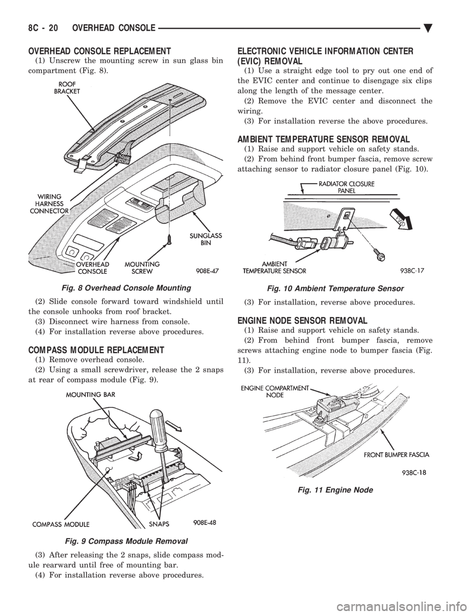
(1) Unscrew the mounting screw in sun glass bin
compartment (Fig. 8).
(2) Slide console forward toward windshield until
the console unhooks from roof bracket. (3) Disconnect wire harness from console.
(4) For installation reverse above procedures.
COMPASS MODULE REPLACEMENT
(1) Remove overhead console.
(2) Using a small screwdriver, release the 2 snaps
at rear of compass module (Fig. 9).
(3) After releasing the 2 snaps, slide compass mod-
ule rearward until free of mounting bar. (4) For installation reverse above procedures.
ELECTRONIC VEHICLE INFORMATION CENTER
(EVIC) REMOVAL
(1) Use a straight edge tool to pry out one end of
the EVIC center and continue to disengage six clips
along the length of the message center. (2) Remove the EVIC center and disconnect the
wiring. (3) For installation reverse the above procedures.
AMBIENT TEMPERATURE SENSOR REMOVAL
(1) Raise and support vehicle on safety stands.
(2) From behind front bumper fascia, remove screw
attaching sensor to radiator closure panel (Fig. 10).
(3) For installation, reverse above procedures.
ENGINE NODE SENSOR REMOVAL
(1) Raise and support vehicle on safety stands.
(2) From behind front bumper fascia, remove
screws attaching engine node to bumper fascia (Fig.
11). (3) For installation, reverse above procedures.
Fig. 8 Overhead Console Mounting
Fig. 9 Compass Module Removal
Fig. 10 Ambient Temperature Sensor
Fig. 11 Engine Node
8C - 20 OVERHEAD CONSOLE Ä
Page 441 of 2438

Test 3 (d3) performs a walking segment test which,
sequentially puts different directions and numbers on
the display. If any segment fails, replace the compass
module.
OVERHEAD CONSOLE REPLACEMENT
(1) Unscrew the mounting screw in sun glass bin
compartment (Fig. 6).
(2) Slide console forward toward windshield until
the console unhooks from roof bracket. (3) Disconnect wire harness from console.
(4) For installation reverse above procedures.
COMPASS MODULE REPLACEMENT
(1) Remove overhead console (Fig 6).
(2) Using a small screwdriver, release the 2 snaps
at rear of compass module (Fig. 7). (3) After releasing the 2 snaps, slide compass mod-
ule rearward until free of mounting bar. (4) For installation reverse above procedures.
AMBIENT TEMPERATURE SENSOR REMOVAL
(1) Raise and support vehicle on safety stands.
(2) Behind front bumper fascia, remove screw at-
taching sensor to radiator closure panel (Fig. 8). (3) For installation, reverse above procedures.
Fig. 6 Overhead Console Mounting
Fig. 7 Compass Module Removal
Fig. 8 Ambient Temperature Sensor
Ä
OVERHEAD CONSOLE 8C - 25
Page 649 of 2438
EXTERIOR LAMPSÐAA BODY INDEX
page page
Center High-Mounted Stop Lamp (CHMSL) Bulb . . 9
Fog Lamp ............................... 9
Fog Lamp Bulb ........................... 9
Front Side Marker Lamp or Bulb .............. 7
Headlamp Bulb ........................... 7 Headlamp Lens
........................... 7
License Plate Lamp or BulbÐAA/P Body ....... 8
License Plate LampsÐAA/C Body ............. 8
Park and Turn Signal Lamp or Bulb ........... 7
Tail, Stop and Turn Signal and Back-Up Lamp . . . 8
HEADLAMP BULB
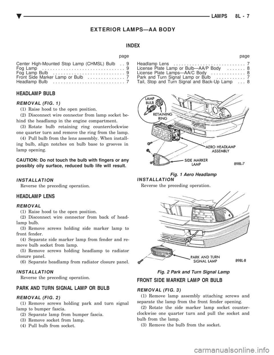
REMOVAL (FIG. 1)
(1) Raise hood to the open position.
(2) Disconnect wire connector from lamp socket be-
hind the headlamp in the engine compartment. (3) Rotate bulb retaining ring counterclockwise
one quarter turn and remove the ring from the lamp. (4) Pull bulb from the lens assembly. When install-
ing bulb, align notches on bulb base to grooves in
lamp opening.
CAUTION: Do not touch the bulb with fingers or any
possibly oily surface, reduced bulb life will result.
INSTALLATION
Reverse the preceding operation.
HEADLAMP LENS
REMOVAL
(1) Raise hood to the open position.
(2) Disconnect wire connector from back of head-
lamp bulb. (3) Remove screws holding side marker lamp to
front fender. (4) Separate side marker lamp from fender and re-
move bulb socket from lamp. (5) Remove screws holding headlamp to radiator
closure panel. (6) Separate headlamp from radiator closure panel.
INSTALLATION
Reverse the preceding operation.
PARK AND TURN SIGNAL LAMP OR BULB
REMOVAL (FIG. 2)
(1) Remove screws holding park and turn signal
lamp to bumper fascia. (2) Separate lamp from bumper fascia.
(3) Remove socket from lamp.
(4) Pull bulb from socket.
INSTALLATION
Reverse the preceding operation.
FRONT SIDE MARKER LAMP OR BULB
REMOVAL (FIG. 3)
(1) Remove lamp assembly attaching screws and
separate the lamp from the front fender opening. (2) Rotate the side marker lamp socket counter-
clockwise one quarter turn and pull the socket and
bulb from the lamp. (3) Remove the bulb from the socket.
Fig. 1 Aero Headlamp
Fig. 2 Park and Turn Signal Lamp
Ä LAMPS 8L - 7
Page 650 of 2438

INSTALLATION
Reverse the preceding operation.
TAIL, STOP AND TURN SIGNAL AND BACK-UP
LAMP
REMOVAL (FIG. 4)
(1) Open deck lid and remove the plastic wing nut
securing the rear trim cover in place. (2) Pivot the end of the trim panel out of the way
to gain access, and remove wing-nuts holding the
lamp to the vehicle. (3) Separate the tail lamp from the body far
enough to rotate the socket and bulb assemblies. Ro-
tate sockets one-half turn and pull the sockets out of
the lamp body. (4) Remove the bulb from the socket.
INSTALLATION
Reverse the preceding operation.
LICENSE PLATE LAMPSÐAA/C Body
REMOVAL (FIG. 5)
(1) Remove screws holding license plate lamp to
rear bumper fascia. (2) Separate license plate lamp from fascia.
(3) Remove socket from license plate lamp.
(4) Pull bulb from socket if bulb replacement is re-
quired.
INSTALLATION
Reverse the preceding operation.
LICENSE PLATE LAMP OR BULBÐAA/P Body
REMOVAL (FIG. 6)
(1) Remove two lamp assembly attaching screws
above the rear license plate opening. (2) Remove the lens from the deck-lid.
(3) Pull the bulb from the socket.
INSTALLATION
Reverse the preceding operation.
Fig. 3 Front Side Marker Lamps
Fig. 4 Rear LightingÐAA/P or AA/D Body
Fig. 5 License Plate LampsÐAA/C Body
Fig. 6 License Plate LampÐAA/P Body
8L - 8 LAMPS Ä
Page 651 of 2438
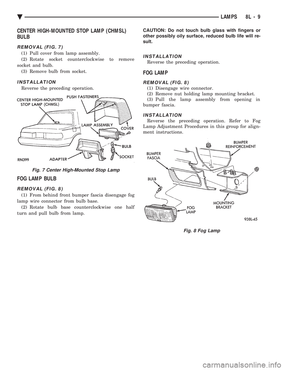
CENTER HIGH-MOUNTED STOP LAMP (CHMSL)
BULB
REMOVAL (FIG. 7)
(1) Pull cover from lamp assembly.
(2) Rotate socket counterclockwise to remove
socket and bulb. (3) Remove bulb from socket.
INSTALLATION
Reverse the preceding operation.
FOG LAMP BULB
REMOVAL (FIG. 8)
(1) From behind front bumper fascia disengage fog
lamp wire connector from bulb base. (2) Rotate bulb base counterclockwise one half
turn and pull bulb from lamp. CAUTION: Do not touch bulb glass with fingers or
other possibly oily surface, reduced bulb life will re-
sult.
INSTALLATION
Reverse the preceding operation.
FOG LAMP
REMOVAL (FIG. 8)
(1) Disengage wire connector.
(2) Remove nut holding lamp mounting bracket.
(3) Pull the lamp assembly from opening in
bumper fascia.
INSTALLATION
Reverse the preceding operation. Refer to Fog
Lamp Adjustment Procedures in this group for align-
ment instructions.
Fig. 7 Center High-Mounted Stop Lamp
Fig. 8 Fog Lamp
Ä LAMPS 8L - 9