1993 CHEVROLET PLYMOUTH ACCLAIM transmission fluid
[x] Cancel search: transmission fluidPage 53 of 2438
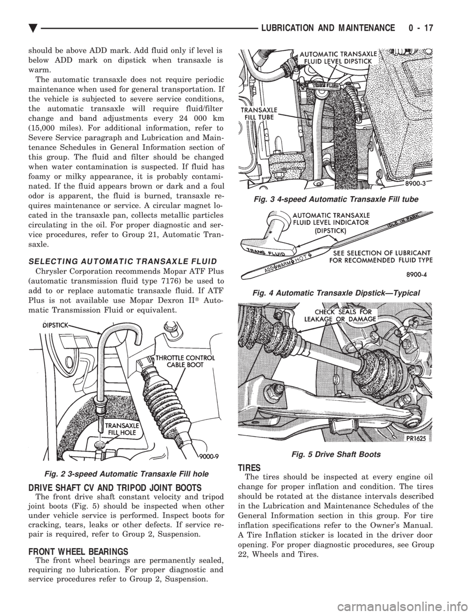
should be above ADD mark. Add fluid only if level is
below ADD mark on dipstick when transaxle is
warm.The automatic transaxle does not require periodic
maintenance when used for general transportation. If
the vehicle is subjected to severe service conditions,
the automatic transaxle will require fluid/filter
change and band adjustments every 24 000 km
(15,000 miles). For additional information, refer to
Severe Service paragraph and Lubrication and Main-
tenance Schedules in General Information section of
this group. The fluid and filter should be changed
when water contamination is suspected. If fluid has
foamy or milky appearance, it is probably contami-
nated. If the fluid appears brown or dark and a foul
odor is apparent, the fluid is burned, transaxle re-
quires maintenance or service. A circular magnet lo-
cated in the transaxle pan, collects metallic particles
circulating in the oil. For proper diagnostic and ser-
vice procedures, refer to Group 21, Automatic Tran-
saxle.
SELECTING AUTOMATIC TRANSAXLE FLUID
Chrysler Corporation recommends Mopar ATF Plus
(automatic transmission fluid type 7176) be used to
add to or replace automatic transaxle fluid. If ATF
Plus is not available use Mopar Dexron II tAuto-
matic Transmission Fluid or equivalent.
DRIVE SHAFT CV AND TRIPOD JOINT BOOTS
The front drive shaft constant velocity and tripod
joint boots (Fig. 5) should be inspected when other
under vehicle service is performed. Inspect boots for
cracking, tears, leaks or other defects. If service re-
pair is required, refer to Group 2, Suspension.
FRONT WHEEL BEARINGS
The front wheel bearings are permanently sealed,
requiring no lubrication. For proper diagnostic and
service procedures refer to Group 2, Suspension.
TIRES
The tires should be inspected at every engine oil
change for proper inflation and condition. The tires
should be rotated at the distance intervals described
in the Lubrication and Maintenance Schedules of the
General Information section in this group. For tire
inflation specifications refer to the Owner's Manual.
A Tire Inflation sticker is located in the driver door
opening. For proper diagnostic procedures, see Group
22, Wheels and Tires.Fig. 2 3-speed Automatic Transaxle Fill hole
Fig. 3 4-speed Automatic Transaxle Fill tube
Fig. 4 Automatic Transaxle DipstickÐTypical
Fig. 5 Drive Shaft Boots
Ä LUBRICATION AND MAINTENANCE 0 - 17
Page 362 of 2438

(2) Remove radiator pressure cap when engine is
cold, Idle engine until thermostat opens, you should
observe coolant flow while looking down the filler
neck. Once flow is detected install radiator pressure
cap.
RADIATOR
REMOVAL
(1) Disconnect negative battery cable from battery.
WARNING: DO NOT REMOVE THE CYLINDER
BLOCK PLUG OR THE RADIATOR DRAINCOCK
WITH THE SYSTEM HOT AND UNDER PRESSURE
BECAUSE SERIOUS BURNS FROM COOLANT CAN
OCCUR.
(2) Drain cooling system. Refer to Draining Cool-
ing System of this section. (3) Remove hose clamps and hoses from the radia-
tor (Fig. 11). Remove coolant reserve system tank to
filler neck tube. (4) Remove automatic transmission hoses, if
equipped. (5) Remove fan and fan support assembly by dis-
connecting fan motor electrical connector. Remove
fan shroud retaining clips, located on the top and
bottom of the shroud for AA, AG, AJ and AP vehi-
cles. AC/AY vehicle retainer clips are located on the
top only. Lift shroud up and out of bottom shroud at-
tachment clips separating shroud from radiator. Fan
damage should always be avoided. (6) Remove upper radiator mounting screws. Dis-
connect the engine block heater wire if equipped. (7) Remove the air conditioning condenser attaching
screws located at the top front of the radiator,if
equipped. Radiator can now be lifted free from engine compart-
ment. Care should be taken not to damage radia-
tor cooling fins or water tubes during removal.
INSTALLATION
(1) Slide radiator down into position behind radiator
support (yoke). (2) Attach air conditioning condenser to radiator, if
equipped, with a force of approximately 10 lbs. to seat
the radiator assembly lower rubber isolators in the
mount holes provided. (3) Tighten radiator mounting screws to 11.9N Im
(105 in. lbs.). (4) Connect automatic transmission hoses, if
equipped. Tighten hose clamps to 4 N Im (35 in. lbs.).
(5) Slide fan shroud, fan and motor down into clips
on lower radiator flange. Replace shroud retaining
clips. (6) Install upper and lower radiator hoses (including
coolant reserve hose). (7) Connect fan motor electrical connection and con-
nect negative battery cable. (8) Fill cooling system with coolant. Refer to Refill-
ing Cooling Systems. in this group.
(9) Operate engine until it reaches normal operating
temperature. Check cooling system and automatic
transmission for correct fluid levels.
Fig. 11 Cooling ModulesÐAll Models
7 - 20 COOLING SYSTEM Ä
Page 933 of 2438
Wiring Diagram
Name Sheet Number
Illumination Lamp ...........................68
Resistor .................................68
Horn System ...............................65
Horn (Hi-Note) .............................65
Horn (Lo-Note) ............................65
Horn Relay ...............................65
Horn Switch ..............................65
Hydraulic Modulator (ABS) 41
Ignition Coil .......................... .14, 20, 29
Ignition Off-Draw Connector .....................5,7
Ignition Switch .............................4,11
Brake Warning Lamp Switch ....................11
Park Brake Switch ...........................11
Illuminated Entry .............................58
Illuminated Entry Module ......................58
Left Door Illuminated Entry Switch ................58
Right Door Illuminated Entry Switch ...............58
Illuminated Visor Vanity Mirror ....................73
Injector(s) ........................... .16, 17, 26
Instrument Panel Wiring to Left Body ...............123
Instrument Panel Wiring to Right Body ..............124
Instrument Panel to Multi-Function Switch ............116
Interface Grommet ............................47
Intermittent Wiper System .................... .63, 64
Intermittent Windshield Wiper Motor ...............64
Intermittent Wiper Control Module ................64
Multi-function Switch .........................63
Windshield Washer Low Fluid Level Sensor ...........63
Windshield Washer Pump Motor .................63
Key-In Switch ...............................46
Key-In Warning Chimes .........................45
Lamp Outage Module ........................ .115
Lamps A/C Lamps ...............................52
Ash Receiver Lamp ..........................52
Back-Up Lamps ............ .93, 94, 98, 102, 103, 105
Cargo Lamp ........................ .76, 96, 100
Center High Mounted Stop Lamp ........94, 98, 102, 105
Cigar Lighter Lamp ..........................52
Cluster Lamp ..............................77
Courtesy Lamps ............................76
Dome Lamp ..............................73
Fog Lamp-Left .............................56
Fog Lamp-Right ............................55
Front Reading Lamp .........................75
Glove Box Lamp ............................54
Halo Lamp ...............................54
Headlamp-Left .............................56
Headlamp Out Lamp .........................77
Headlamp-Right ............................55
Heater Lamp ..............................52
Illumination Lamp ..................... .68, 71, 72
Left Front Door Ajar Lamp .....................77
Left Rear Door Ajar Lamp ......................77
Left Side Marker Lamp ........................93
Left Tail/Stop and Turn Lamp ....................93
License Lamp ................... .93, 98, 102, 104Wiring Diagram
Name Sheet Number
Liftgate Ajar Lamp ..........................77
Low Washer Fluid Lamp .......................77
Park/Turn Lamp-Left .........................56
Park/Turn Lamp-Right ........................55
Radio Lamp ...............................52
Reading Lamps ............................75
Right Front Door Ajar Lamp ....................77
Right Rear Door Ajar Lamp .....................77
Seat Belt Warning Lamp .......................45
Side Marker Lamp-Left Front ....................56
Side Marker Lamp-Left Rear ...........93, 98, 102, 103
Side Marker Lamp-Right Front ...................55
Side Marker Lamp-Right Rear ..........94, 98, 102, 105
Stop Lamp Out Lamp ........................77
Tail Lamp Out Lamp .........................77
Tail/Stop Lamp-Left Rear ................... .93, 98
Tail/Stop Lamp-Right Rear .................. .94, 98
Tail/Stop and Turn Lamp-Left Rear .......93, 98, 102, 103
Tail/Stop and Turn Lamp-Right Rear ......94, 98, 102, 105
Transmission Range Indicator Lamp ...............76
Underhood Lamp ........................ .39, 40
Visor Vanity Mirror Lamp ......................73
Left Power Seat System ........................66
Center Switch .............................66
Front Switch ..............................66
Power Seat Motors ..........................66
Rear Switch ...............................66
License Lamp ..................... .93, 98, 102, 104
Lighter-Cigar ................................52
MAP Sensor .......................... .13, 19, 30
Message Center ..............................60
Traveler and Message Center ....................60
Mini Trip Computer ...........................60
Modules Airbag System Diagnostic Module .................47
Daytime Running Light Module ..................57
Illuminated Entry Module ......................58
Intermittent Wiper Control Module ................64
Lamp Outage Module ..................... .95, 99
Motors A/C-Heater Blower Motor ................... .71, 72
Fuel Pump Motor ...........................69
Heater Blower Motor .........................68
Idle Air Control Motor .................. .12, 18, 30
Intermittent Wiper Motor ......................64
Power Door Locks Motors .................. .85, 86
Power Seat Motors ..........................66
Power Window Motors .................... .81, 82
Radiator Fan Motor ...................... .32, 33
Starter Motor ............................9,10
Windshield Washer Pump Motor .................63
Name Brand Speaker Relay ......................89
Optical Horn Headlamp Dimmer Switch .............1,50
Overhead Console, Dome, Reading and Visor Vanity Lamps ..................... .73, 74, 75, 76
Ambient Temperature Sensor ....................75
Cargo Lamp ..............................76
Ä WIRING DIAGRAMS AA-BODY 8W - 183
Page 935 of 2438
Wiring Diagram
Name Sheet Number
Seat Belt Switch ............................46
Seat Belt Warning Chime ......................45
Seat Belt Warning Lamp .......................45
Sensors Airbag Sensor .............................47
Ambient Temperature Sensor ....................75
Engine Coolant Sensor .................. .15, 21, 27
Fuel Sensor ...............................17
Heated Oxygen Sensor .................. .12, 18, 24
Left Front Wheel Sensor .......................42
Left Rear Wheel Sensor .......................42
MAP Sensor ........................ .13, 19, 30
Output Speed Sensor .........................38
Right Front Wheel Sensor ......................42
Right Rear Wheel Sensor ......................42
Throttle Position (Sensor) .................12, 18, 24
Turbine Speed Sensor ........................38
Vehicle Speed Sensor .................. .15, 21, 28
Windshield Washer Low Fluid Sensor ..............63
Solenoids EMCC Solenoid .............................9
EVAP/Purge Solenoid ................... .13, 19, 23
Exhaust Gas Recirculation Diagnostic Solenoid ......13, 24
Transmission Solenoid ........................35
Speakers-Front Door and Rear w/o Name Brand Speakers . . .88 Left Front Door Speaker .......................88
Left Rear Door Speaker .......................88
Right Front Door Speaker ......................88
Right Rear Door Speaker ......................88
Speaker Choke ..............................89
Speakers-Front Door and Rear w/Name Brand Speakers ............................. .90, 91
Left Front Door Speakers ......................90
Left Rear Door Speaker .......................91
Right Front Door Speaker ......................90
Right Rear Door Speaker ......................91
Splices Splice A0 .....................1,2,4,6,8,39,40
Splice A1 .................................6
Splice A3 .......................... .48, 59, 67
Splice A4 ......................4,5,8,34,39,40
Splice A14 ..............................6,8
Splice A15 ..............................5,7
Splice A15-1 ...........................1,5,7
Splice A20 ............................6,8,43
Splice A21 ...............................??
Splice A21-1 ........................ .13, 19, 23
Splice A21-2 ...................... .13, 19, 23, 44
Splice A21-3 ..............................37
Splice A41 ...............................10
Splice A61 ...............................17
Splice A142 ......................6,8,14,20,24
Splice A142-1 .........................8,14,20
Splice A142-2 .............................26
Splice A142-4 .............................26
Splice B47 ...............................43
Splice B120 ...............................41Wiring Diagram
Name Sheet Number
Splice C7 .......................... .68, 71, 72
Splice D1 ................................34
Splice D2 ................................34
Splice E2-1 ............... .51, 68, 71, 72, 84, 87, 89
Splice E2-2 ............... .52, 68, 71, 72, 84, 87, 89
Splice E17 ...............................49
Splice F20 .................9,16,22,37,47,60,84
Splice F30 ...................... .45, 47, 48, 106
Splice F35 .......................... .66, 67, 85
Splice G5 ........................ .44, 45, 47, 77
Splice G7-1 ......................... .15, 21, 27
Splice G16 ...............................46
Splice G26 ........................... .45, 106
Splice K4 ................................24
Splice K4-1 ........................... .15, 21
Splice K4-2 ......................... .15, 21, 27
Splice K6 .......................... .13, 19, 25
Splice K7 .......................... .16, 22, 27
Splice K7-1 ...............................22
Splice K22 ...............................25
Splice K24 ...............................27
Splice L1 ...................... .93, 97, 101, 103
Splice L3 ................................55
Splice L7 ........................ .50, 56, 95, 99
Splice L7-1 ...............................56
Splice L7-2 ...............................55
Splice L7-3 ..................... .92, 97, 101, 103
Splice L20 ..............................1,49
Splice L39 ...............................55
Splice L43 ...............................56
Splice L60 ...............................55
Splice L61 ...............................56
Splice M1 ................................73
Splice M1-2 ................... .53, 74, 80, 87, 89
Splice M1-3 ........................ .39, 40, 53
Splice M1-4 ........................ .58, 76, 80
Splice M1-5 ........................... .58, 74
Splice M2-3 ........................... .54, 74
Splice M2-4 ........................... .58, 76
Splice M2-5 ........................... .58, 74
Splice P33 ...............................86
Splice P34 ...............................86
Splice Q1-1 ...............................82
Splice T13 ...............................38
Splice T16 ...............................35
Splice T41 ............................ .10, 37
Splice V6 ............................. .11, 64
Splice X13 ...............................90
Splice X15 ...............................90
Splice Z0 ..........................5,7,29,36
Splice Z1 ..............5,43,63,93,94,98, 102, 103
Splice Z1-1 ............... .32, 33, 49, 51, 56, 59, 84
Splice Z1-2 ................. .43, 52, 55, 68, 71, 72
Splice Z1-3 ........................... .41, 56
Splice Z1-4 .......46, 66, 69, 79, 82, 85, 92, 97, 101, 103
Splice Z1-5 ................. .46, 66, 69, 79, 82, 85
Splice Z1-7 ...............................98
Ä WIRING DIAGRAMS AA-BODY 8W - 185
Page 1065 of 2438
Wiring Diagram
Name Sheet Number
RS Amplifier ......................... .122, 123
Electronic Cluster ........................ .99, 100
Data Link Connector ....................... .100
Electronic Cluster Printed Circuit Board Connector .......201
Electronic Fuel Pump and Gauge System ..............36
Electronic Vehicle Information Center Connector ........189
Electronic Vehicle Information Center Engine Compartment Sensors ...................... .97, 98
Brake Fluid Level Sensor ......................98
Coolant Level Sensor .........................98
Data Link Connector .........................97
EVIC Engine Node ...........................98
Engine Air Conditioning and Heater System (3.0L, 3.3L & 3.8L Engine) ................55
A/C and Heater Blower Motor Resistor ..............55
A/C Blower Motor ...........................55
A/C Low Pressure Switch ......................55
A/C Switch ...............................55
A/C Variable Output Compressor Clutch .............55
Blower Switch .............................55
Defrost Switch .............................55
Illumination Lamps ..........................55
Engine Coolant Temperature Sending Unit ........30, 31, 32
Engine Coolant Temperature Sensor ..............19, 25
Engine Oil Level Sensor ..................... .31, 32
Engine Oil Pressure and Temperature Warning System (2.5L) .............................30
Engine Coolant Temperature Sending Unit ............30
Engine Oil Pressure Switch .....................30
Engine Oil Pressure and Temperature Warning System (3.0L) .............................31
Engine Coolant Temperature Sending Unit ............31
Engine Oil Level Sensor .......................31
Engine Oil Pressure Sending Unit/Switch ............31
Engine Oil Pressure and Temperature Warning System (3.3L & 3.8L) .............................32
Engine Coolant Temperature Sending Unit ............32
Engine Oil Level Sensor .......................32
Engine Oil Pressure Sending Unit/Switch ............32
Engine Starter System (2.5L) .....................12
Automatic Park/Neutral Start Switch ...............12
Back-Up Lamp Switch ........................12
Engine Starter Motor .........................12
Engine Starter Relay .........................12
Transmission Solenoid ........................12
Engine Starter System (3.0L, 3.3L & 3.8L) .............13
Engine Starter Motor .........................13
Engine Starter Relay .........................13
Electronic Fuel Pump and Gauge System ..............36
Fuel Pump Motor ...........................36
Fuel Pump Relay ...........................36
Fuel Tank Level Gauge Sending Unit Fuel Switch .......36
EVAP/Purge Solenoid .................... .15, 20, 27
Fan Control Relay ......................... .52, 54
Front End Lighting-Aero Headlamps (Dodge Dynasty) . . .69, 70 Left Headlamp (Aero) .........................70
Left Park/Turn Signal Lamp .....................70
Left Side Marker Lamp ........................70Wiring Diagram
Name Sheet Number
Right Headlamp (Aero) ........................69
Right Park/Turn Signal Lamp ....................69
Right Side Marker Lamp .......................69
Front End Lighting-Aero Headlamps with Daytime Running Lights (Dodge Dynasty) .................... .71, 72
Daytime Running Lamp Module ..................72
Left Headlamp (Aero) .........................72
Left Park/Turn Signal Lamp .....................72
Left Side Marker Lamp ........................72
Right Headlamp (Aero) ........................71
Right Park/Turn Signal Lamp ....................71
Right Side Marker Lamp .......................71
Front End Lighting Concealed Headlamps (Imperial) . . . .73, 74
Left Cornering Lamp .........................74
Left High Beam Headlamp ......................74
Left Low Beam Headlamp ......................74
Left Park Lamps ............................74
Left Park/Turn Signal Lamp .....................74
Left Side Turn Lamp .........................74
Right Cornering Lamp ........................73
Right High Beam Headlamp .....................73
Right Low Beam Headlamp .....................73
Right Park Lamps ...........................73
Right Park/Turn Signal Lamp ....................73
Right Side Turn Lamp ........................73
Front End Lighting Concealed Headlamps with D.R.L.1 (Imperial) .......................... .75, 76, 77
Daytime Running Lamp Module ..................76
Left Cornering Lamp .........................77
Left High Beam Headlamp ......................77
Left Low Beam Headlamp ......................77
Left Park Lamps ............................77
Left Park/Turn Signal Lamp .....................77
Left Side Turn Lamp .........................77
Right Cornering Lamp ........................75
Right High Beam Headlamp .....................75
Right Low Beam Headlamp .....................75
Right Park Lamps ...........................75
Right Park/Turn Signal Lamp ....................75
Right Side Turn Lamp ........................75
Front End Lighting Concealed Headlamps with D.R.L.2 (Imperial) .......................... .78, 79, 80
Daytime Running Lamp Module ..................79
Left Cornering Lamp .........................80
Left High Beam Headlamp ......................80
Left Low Beam Headlamp ......................80
Left Park Lamps ............................80
Left Park/Turn Signal Lamp .....................80
Left Side Turn Lamp .........................80
Right Cornering Lamp ........................78
Right High Beam Headlamp .....................78
Right Low Beam Headlamp .....................78
Right Park Lamps ...........................78
Right Park/Turn Signal Lamp ....................78
Right Side Turn Lamp ........................78
Front End Lighting Concealed Headlamps (New Yorker/5th Avenue) .............................. .81, 82
Ä WIRING DIAGRAMS AC-AY BODY 8W - 315
Page 1067 of 2438
Wiring Diagram
Name Sheet Number
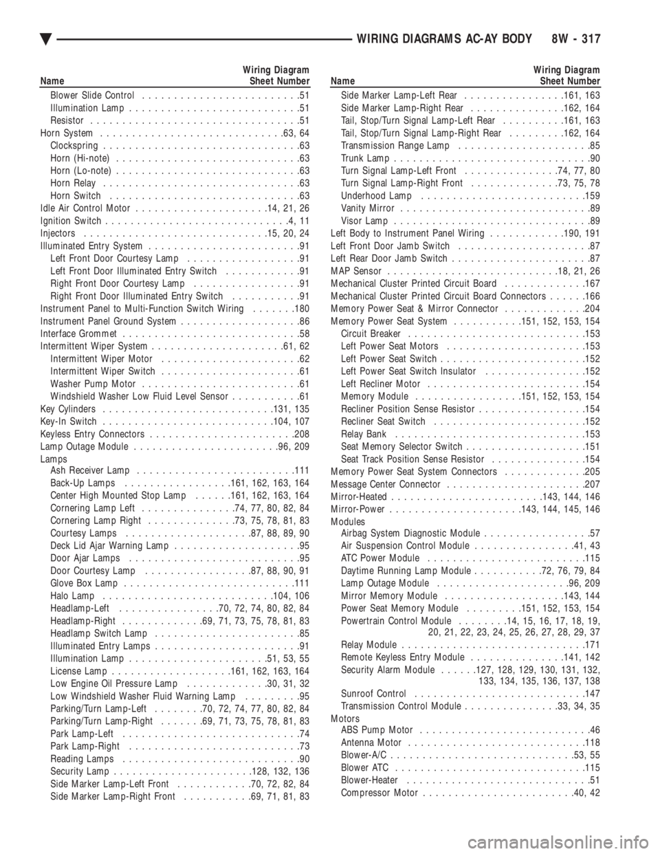
Blower Slide Control .........................51
Illumination Lamp ...........................51
Resistor .................................51
Horn System ............................ .63, 64
Clockspring ...............................63
Horn (Hi-note) .............................63
Horn (Lo-note) .............................63
Horn Relay ...............................63
Horn Switch ..............................63
Idle Air Control Motor .................... .14, 21, 26
Ignition Switch .............................4,11
Injectors ............................ .15, 20, 24
Illuminated Entry System ........................91
Left Front Door Courtesy Lamp ..................91
Left Front Door Illuminated Entry Switch ............91
Right Front Door Courtesy Lamp .................91
Right Front Door Illuminated Entry Switch ...........91
Instrument Panel to Multi-Function Switch Wiring .......180
Instrument Panel Ground System ...................86
Interface Grommet ............................58
Intermittent Wiper System .................... .61, 62
Intermittent Wiper Motor ......................62
Intermittent Wiper Switch ......................61
Washer Pump Motor .........................61
Windshield Washer Low Fluid Level Sensor ...........61
Key Cylinders .......................... .131, 135
Key-In Switch .......................... .104, 107
Keyless Entry Connectors ...................... .208
Lamp Outage Module ...................... .96, 209
Lamps Ash Receiver Lamp ........................ .111
Back-Up Lamps ................ .161, 162, 163, 164
Center High Mounted Stop Lamp ......161, 162, 163, 164
Cornering Lamp Left ...............74, 77, 80, 82, 84
Cornering Lamp Right ..............73, 75, 78, 81, 83
Courtesy Lamps ................... .87, 88, 89, 90
Deck Lid Ajar Warning Lamp ....................95
Door Ajar Lamps ...........................95
Door Courtesy Lamp ................ .87, 88, 90, 91
Glove Box Lamp .......................... .111
Halo Lamp .......................... .104, 106
Headlamp-Left ............... .70, 72, 74, 80, 82, 84
Headlamp-Right ............ .69, 71, 73, 75, 78, 81, 83
Headlamp Switch Lamp .......................85
Illuminated Entry Lamps .......................91
Illumination Lamp ..................... .51, 53, 55
License Lamp .................. .161, 162, 163, 164
Low Engine Oil Pressure Lamp .............30, 31, 32
Low Windshield Washer Fluid Warning Lamp .........95
Parking/Turn Lamp-Left ........70, 72, 74, 77, 80, 82, 84
Parking/Turn Lamp-Right .......69, 71, 73, 75, 78, 81, 83
Park Lamp-Left ............................74
Park Lamp-Right ...........................73
Reading Lamps ............................90
Security Lamp ..................... .128, 132, 136
Side Marker Lamp-Left Front ............70, 72, 82, 84
Side Marker Lamp-Right Front ...........69, 71, 81, 83Wiring Diagram
Name Sheet Number
Side Marker Lamp-Left Rear ................161, 163
Side Marker Lamp-Right Rear ...............162, 164
Tail, Stop/Turn Signal Lamp-Left Rear ..........161, 163
Tail, Stop/Turn Signal Lamp-Right Rear .........162, 164
Transmission Range Lamp .....................85
Trunk Lamp ...............................90
Turn Signal Lamp-Left Front ...............74, 77, 80
Turn Signal Lamp-Right Front ..............73, 75, 78
Underhood Lamp ......................... .159
Vanity Mirror ..............................89
Visor Lamp ...............................89
Left Body to Instrument Panel Wiring ............190, 191
Left Front Door Jamb Switch .....................87
Left Rear Door Jamb Switch ......................87
MAP Sensor .......................... .18, 21, 26
Mechanical Cluster Printed Circuit Board .............167
Mechanical Cluster Printed Circuit Board Connectors ......166
Memory Power Seat & Mirror Connector .............204
Memory Power Seat System ...........151, 152, 153, 154
Circuit Breaker ........................... .153
Left Power Seat Motors ..................... .153
Left Power Seat Switch ...................... .152
Left Power Seat Switch Insulator ................152
Left Recliner Motor ........................ .154
Memory Module ................ .151, 152, 153, 154
Recliner Position Sense Resistor .................154
Recliner Seat Switch ....................... .152
Relay Bank ............................. .153
Seat Memory Selector Switch ...................151
Seat Track Position Sense Resistor ...............154
Memory Power Seat System Connectors .............205
Message Center Connector ..................... .207
Mirror-Heated ....................... .143, 144, 146
Mirror-Power .................... .143, 144, 145, 146
Modules Airbag System Diagnostic Module .................57
Air Suspension Control Module ................41, 43
ATC Power Module ........................ .115
Daytime Running Lamp Module ...........72, 76, 79, 84
Lamp Outage Module .................... .96, 209
Mirror Memory Module .................. .143, 144
Power Seat Memory Module .........151, 152, 153, 154
Powertrain Control Module ........14, 15, 16, 17, 18, 19,
20, 21, 22, 23, 24, 25, 26, 27, 28, 29, 37
Relay Module ............................ .171
Remote Keyless Entry Module ...............141, 142
Security Alarm Module ......127, 128, 129, 130, 131, 132,
133, 134, 135, 136, 137, 138
Sunroof Control .......................... .147
Transmission Control Module ...............33, 34, 35
Motors ABS Pump Motor ...........................46
Antenna Motor ........................... .118
Blower-A/C ............................ .53, 55
Blower ATC ............................. .115
Blower-Heater .............................51
Compressor Motor ....................... .40, 42
Ä WIRING DIAGRAMS AC-AY BODY 8W - 317
Page 1069 of 2438
Wiring Diagram
Name Sheet Number
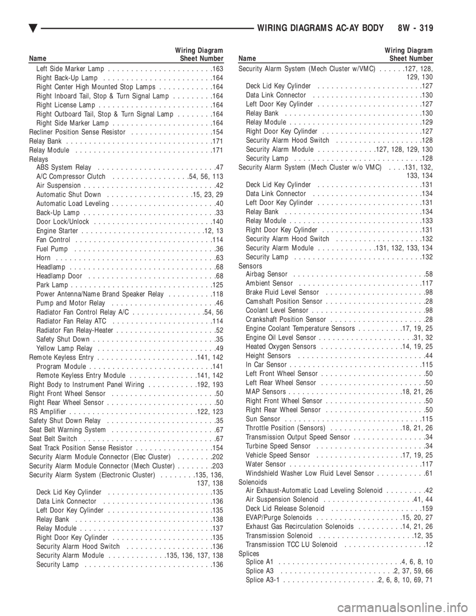
Left Side Marker Lamp ...................... .163
Right Back-Up Lamp ....................... .164
Right Center High Mounted Stop Lamps ............164
Right Inboard Tail, Stop & Turn Signal Lamp .........164
Right License Lamp ........................ .164
Right Outboard Tail, Stop & Turn Signal Lamp ........164
Right Side Marker Lamp ..................... .164
Recliner Position Sense Resistor ..................154
Relay Bank ............................... .171
Relay Module ............................. .171
Relays ABS System Relay ..........................47
A/C Compressor Clutch .................54, 56, 113
Air Suspension .............................42
Automatic Shut Down .................. .15, 23, 29
Automatic Load Leveling .......................40
Back-Up Lamp .............................33
Door Lock/Unlock ......................... .140
Engine Starter .......................... .12, 13
Fan Control ............................. .114
Fuel Pump ...............................36
Horn ...................................63
Headlamp ................................68
Headlamp Door ............................68
Park Lamp .............................. .125
Power Antenna/Name Brand Speaker Relay ..........118
Pump and Motor Relay .......................46
Radiator Fan Control Relay A/C ................54, 56
Radiator Fan Relay ATC ..................... .114
Radiator Fan Relay-Heater ......................52
Safety Shut Down ...........................35
Yellow Lamp Relay ..........................49
Remote Keyless Entry ..................... .141, 142
Program Module .......................... .141
Remote Keyless Entry Module ...............141, 142
Right Body to Instrument Panel Wiring ...........192, 193
Right Front Wheel Sensor .......................50
Right Rear Wheel Sensor ........................50
RS Amplifier ........................... .122, 123
Safety Shut Down Relay ........................35
Seat Belt Warning System .......................67
Seat Belt Switch .............................67
Seat Track Position Sense Resistor .................154
Security Alarm Module Connector (Elec Cluster) ........202
Security Alarm Module Connector (Mech Cluster) ........203
Security Alarm System (Electronic Cluster) ........135, 136,
137, 138
Deck Lid Key Cylinder ...................... .135
Data Link Connector ....................... .136
Left Door Key Cylinder ...................... .135
Relay Bank ............................. .138
Relay Module ............................ .137
Right Door Key Cylinder ..................... .135
Security Alarm Hood Switch ...................136
Security Alarm Module .............135, 136, 137, 138
Security Lamp ........................... .136Wiring Diagram
Name Sheet Number
Security Alarm System (Mech Cluster w/VMC) ......127, 128,
129, 130
Deck Lid Key Cylinder ...................... .127
Data Link Connector ....................... .130
Left Door Key Cylinder ...................... .127
Relay Bank ............................. .130
Relay Module ............................ .129
Right Door Key Cylinder ..................... .127
Security Alarm Hood Switch ...................128
Security Alarm Module .............127, 128, 129, 130
Security Lamp ........................... .128
Security Alarm System (Mech Cluster w/o VMC) . . . .131, 132,
133, 134
Deck Lid Key Cylinder ...................... .131
Data Link Connector ....................... .134
Left Door Key Cylinder ...................... .131
Relay Bank ............................. .134
Relay Module ............................ .133
Right Door Key Cylinder ..................... .131
Security Alarm Hood Switch ...................132
Security Alarm Module .............131, 132, 133, 134
Security Lamp ........................... .132
Sensors Airbag Sensor .............................58
Ambient Sensor .......................... .117
Brake Fluid Level Sensor ......................98
Camshaft Position Sensor ......................28
Coolant Level Sensor .........................98
Crankshaft Position Sensor .....................28
Engine Coolant Temperature Sensors ..........17, 19, 25
Engine Oil Level Sensor .................... .31, 32
Heated Oxygen Sensors ................. .14, 19, 25
Height Sensors ............................44
In Car Senso r............................ .115
Left Front Wheel Sensor .......................50
Left Rear Wheel Sensor .......................50
MAP Sensors ........................ .18, 21, 26
Right Front Wheel Sensor ......................50
Right Rear Wheel Sensor ......................50
Sun Sensor ............................. .115
Throttle Position (Sensors) ................18, 21, 26
Transmission Output Speed Sensor ................34
Turbine Speed Sensor ........................34
Vehicle Speed Sensor .................. .17, 19, 25
Water Sensor ............................ .117
Windshield Washer Low Fluid Level Sensor ...........61
Solenoids Air Exhaust-Automatic Load Leveling Solenoid .........42
Air Suspension Solenoid ................... .41, 44
Deck Lid Release Solenoid ................... .159
EVAP/Purge Solenoids .................. .15, 20, 27
Exhaust Gas Recirculation Solenoids ..........14, 21, 26
Transmission Solenoid .................... .12, 35
Transmission TCC LU Solenoid ..................12
Splices Splice A1 ...........................4,6,8,10
Splice A3 .........................2,37,59,66
Splice A3-1 .....................2,6,8,10,69,71
Ä WIRING DIAGRAMS AC-AY BODY 8W - 319
Page 1284 of 2438
Wiring Diagram
Name Sheet Number
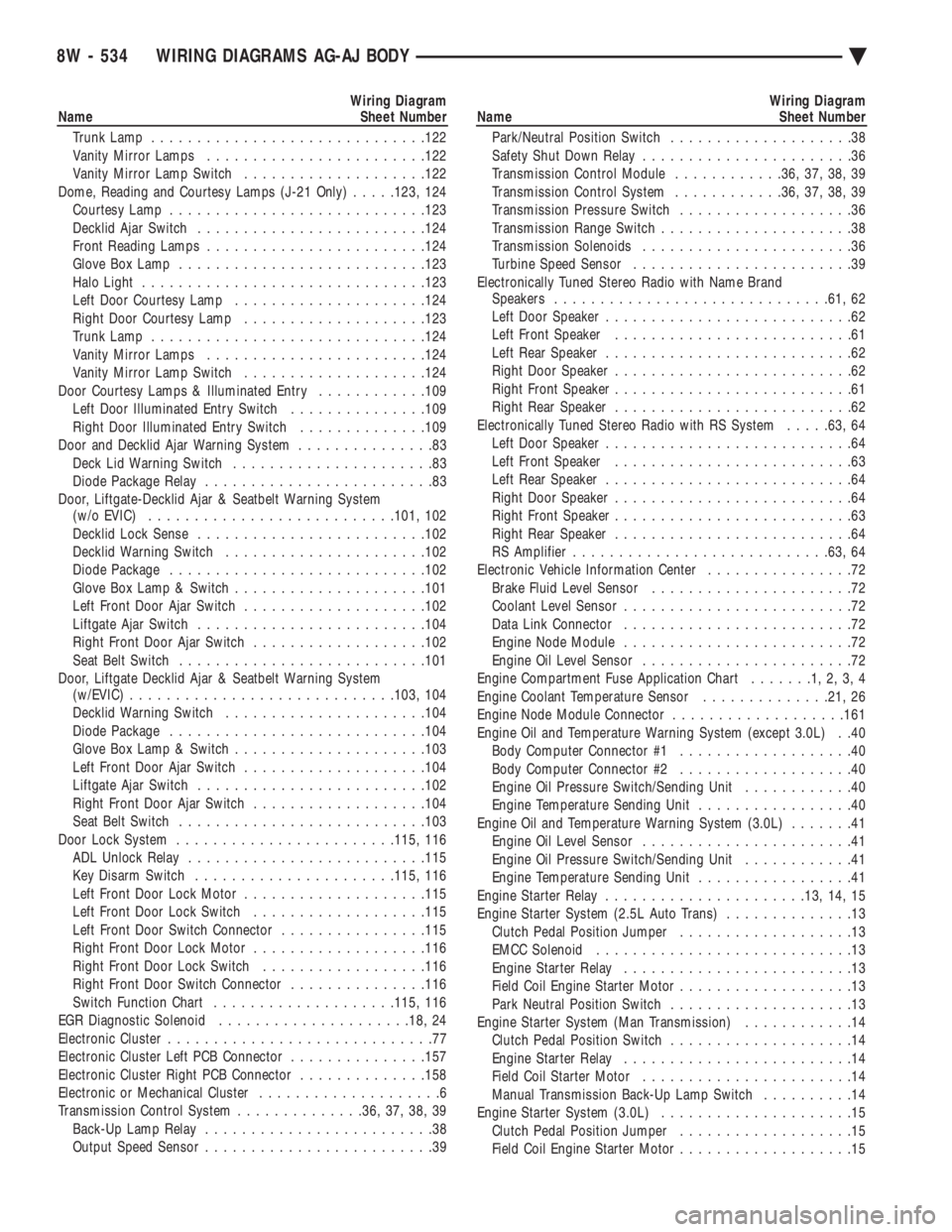
Trunk Lamp ............................. .122
Vanity Mirror Lamps ....................... .122
Vanity Mirror Lamp Switch ................... .122
Dome, Reading and Courtesy Lamps (J-21 Only) .....123, 124
Courtesy Lamp ........................... .123
Decklid Ajar Switch ........................ .124
Front Reading Lamps ....................... .124
Glove Box Lamp .......................... .123
Halo Light .............................. .123
Left Door Courtesy Lamp .................... .124
Right Door Courtesy Lamp ................... .123
Trunk Lamp ............................. .124
Vanity Mirror Lamps ....................... .124
Vanity Mirror Lamp Switch ................... .124
Door Courtesy Lamps & Illuminated Entry ............109
Left Door Illuminated Entry Switch ...............109
Right Door Illuminated Entry Switch ..............109
Door and Decklid Ajar Warning System ...............83
Deck Lid Warning Switch ......................83
Diode Package Relay .........................83
Door, Liftgate-Decklid Ajar & Seatbelt Warning System (w/o EVIC) .......................... .101, 102
Decklid Lock Sense ........................ .102
Decklid Warning Switch ..................... .102
Diode Package ........................... .102
Glove Box Lamp & Switch .................... .101
Left Front Door Ajar Switch ................... .102
Liftgate Ajar Switch ........................ .104
Right Front Door Ajar Switch ...................102
Seat Belt Switch .......................... .101
Door, Liftgate Decklid Ajar & Seatbelt Warning System (w/EVIC) ............................ .103, 104
Decklid Warning Switch ..................... .104
Diode Package ........................... .104
Glove Box Lamp & Switch .................... .103
Left Front Door Ajar Switch ................... .104
Liftgate Ajar Switch ........................ .102
Right Front Door Ajar Switch ...................104
Seat Belt Switch .......................... .103
Door Lock System ....................... .115, 116
ADL Unlock Relay ......................... .115
Key Disarm Switch ..................... .115, 116
Left Front Door Lock Motor ................... .115
Left Front Door Lock Switch ...................115
Left Front Door Switch Connector ................115
Right Front Door Lock Motor ...................116
Right Front Door Lock Switch ..................116
Right Front Door Switch Connector ...............116
Switch Function Chart ................... .115, 116
EGR Diagnostic Solenoid .................... .18, 24
Electronic Cluster .............................77
Electronic Cluster Left PCB Connector ...............157
Electronic Cluster Right PCB Connector ..............158
Electronic or Mechanical Cluster ....................6
Transmission Control System ..............36, 37, 38, 39
Back-Up Lamp Relay .........................38
Output Speed Sensor .........................39Wiring Diagram
Name Sheet Number
Park/Neutral Position Switch ....................38
Safety Shut Down Relay .......................36
Transmission Control Module ............36, 37, 38, 39
Transmission Control System ............36, 37, 38, 39
Transmission Pressure Switch ...................36
Transmission Range Switch .....................38
Transmission Solenoids .......................36
Turbine Speed Sensor ........................39
Electronically Tuned Stereo Radio with Name Brand Speakers ............................. .61, 62
Left Door Speaker ...........................62
Left Front Speaker ..........................61
Left Rear Speaker ...........................62
Right Door Speaker ..........................62
Right Front Speaker ..........................61
Right Rear Speaker ..........................62
Electronically Tuned Stereo Radio with RS System .....63, 64
Left Door Speaker ...........................64
Left Front Speaker ..........................63
Left Rear Speaker ...........................64
Right Door Speaker ..........................64
Right Front Speaker ..........................63
Right Rear Speaker ..........................64
RS Amplifier ........................... .63, 64
Electronic Vehicle Information Center ................72
Brake Fluid Level Sensor ......................72
Coolant Level Sensor .........................72
Data Link Connector .........................72
Engine Node Module .........................72
Engine Oil Level Sensor .......................72
Engine Compartment Fuse Application Chart .......1,2,3,4
Engine Coolant Temperature Sensor ..............21, 26
Engine Node Module Connector ...................161
Engine Oil and Temperature Warning System (except 3.0L) . .40 Body Computer Connector #1 ...................40
Body Computer Connector #2 ...................40
Engine Oil Pressure Switch/Sending Unit ............40
Engine Temperature Sending Unit .................40
Engine Oil and Temperature Warning System (3.0L) .......41
Engine Oil Level Sensor .......................41
Engine Oil Pressure Switch/Sending Unit ............41
Engine Temperature Sending Unit .................41
Engine Starter Relay ..................... .13, 14, 15
Engine Starter System (2.5L Auto Trans) ..............13
Clutch Pedal Position Jumper ...................13
EMCC Solenoid ............................13
Engine Starter Relay .........................13
Field Coil Engine Starter Motor ...................13
Park Neutral Position Switch ....................13
Engine Starter System (Man Transmission) ............14
Clutch Pedal Position Switch ....................14
Engine Starter Relay .........................14
Field Coil Starter Motor .......................14
Manual Transmission Back-Up Lamp Switch ..........14
Engine Starter System (3.0L) .....................15
Clutch Pedal Position Jumper ...................15
Field Coil Engine Starter Motor ...................15
8W - 534 WIRING DIAGRAMS AG-AJ BODY Ä