1993 CHEVROLET PLYMOUTH ACCLAIM rear view mirror
[x] Cancel search: rear view mirrorPage 681 of 2438
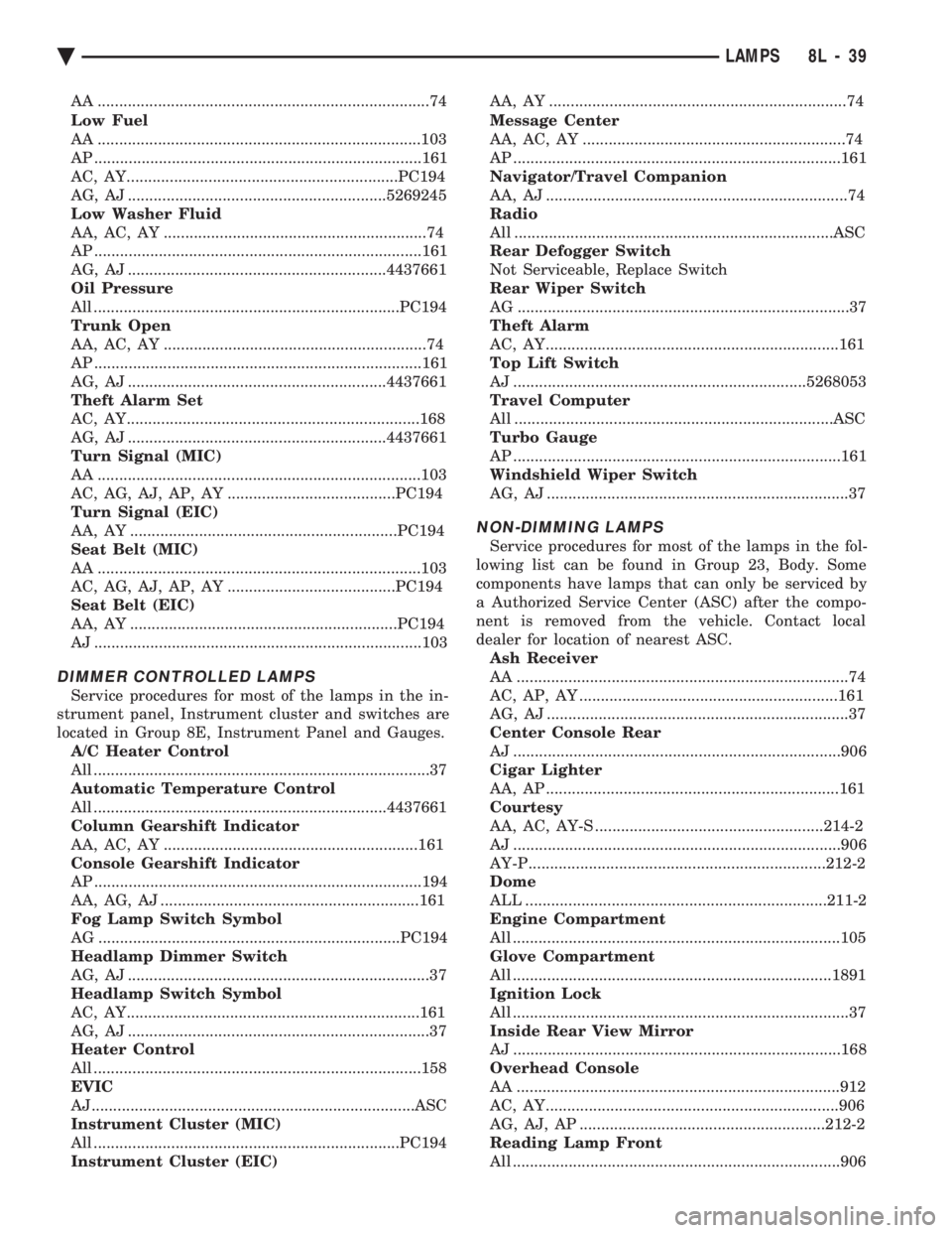
AA .............................................................................74
Low Fuel
AA ...........................................................................103
AP ............................................................................161
AC, AY...............................................................PC194
AG, AJ ............................................................5269245
Low Washer Fluid
AA, AC, AY .............................................................74
AP ............................................................................161
AG, AJ ............................................................4437661
Oil Pressure
All .......................................................................PC194
Trunk Open
AA, AC, AY .............................................................74
AP ............................................................................161
AG, AJ ............................................................4437661
Theft Alarm Set
AC, AY....................................................................168
AG, AJ ............................................................4437661
Turn Signal (MIC)
AA ...........................................................................103
AC, AG, AJ, AP, AY .......................................PC194
Turn Signal (EIC)
AA, AY ..............................................................PC194
Seat Belt (MIC)
AA ...........................................................................103
AC, AG, AJ, AP, AY .......................................PC194
Seat Belt (EIC)
AA, AY ..............................................................PC194
AJ ............................................................................103
DIMMER CONTROLLED LAMPS
Service procedures for most of the lamps in the in-
strument panel, Instrument cluster and switches are
located in Group 8E, Instrument Panel and Gauges. A/C Heater Control
All ..............................................................................37
Automatic Temperature Control
All ....................................................................4437661
Column Gearshift Indicator
AA, AC, AY ...........................................................161
Console Gearshift Indicator
AP ............................................................................194
AA, AG, AJ ............................................................161
Fog Lamp Switch Symbol
AG ......................................................................PC194
Headlamp Dimmer Switch
AG, AJ ......................................................................37
Headlamp Switch Symbol
AC, AY....................................................................161
AG, AJ ......................................................................37
Heater Control
All ............................................................................158
EVIC
AJ...........................................................................ASC
Instrument Cluster (MIC)
All .......................................................................PC194
Instrument Cluster (EIC) AA, AY .....................................................................74
Message Center
AA, AC, AY .............................................................74
AP ............................................................................161
Navigator/Travel Companion
AA, AJ ......................................................................74
Radio
All ..........................................................................ASC
Rear Defogger Switch
Not Serviceable, Replace Switch
Rear Wiper Switch
AG .............................................................................37
Theft Alarm
AC, AY....................................................................161
Top Lift Switch
AJ ....................................................................5268053
Travel Computer
All ..........................................................................ASC
Turbo Gauge
AP ............................................................................161
Windshield Wiper Switch
AG, AJ ......................................................................37
NON-DIMMING LAMPS
Service procedures for most of the lamps in the fol-
lowing list can be found in Group 23, Body. Some
components have lamps that can only be serviced by
a Authorized Service Center (ASC) after the compo-
nent is removed from the vehicle. Contact local
dealer for location of nearest ASC. Ash Receiver
AA .............................................................................74
AC, AP, AY ............................................................161
AG, AJ ......................................................................37
Center Console Rear
AJ ............................................................................906
Cigar Lighter
AA, AP ....................................................................161
Courtesy
AA, AC, AY-S .....................................................214-2
AJ ............................................................................906
AY-P.....................................................................212-2
Dome
ALL ......................................................................211-2
Engine Compartment
All ............................................................................105
Glove Compartment
All ..........................................................................1891
Ignition Lock
All ..............................................................................37
Inside Rear View Mirror
AJ ............................................................................168
Overhead Console
AA ...........................................................................912
AC, AY....................................................................906
AG, AJ, AP .........................................................212-2
Reading Lamp Front
All ............................................................................906
Ä LAMPS 8L - 39
Page 711 of 2438

wing. Refer to Owner Manual supplied with vehicle
for complete instructions for seat operation.
SWITCH TEST
For switch testing, remove switch from its mount-
ing location. Using an ohmmeter, refer to Figures 13
and 14 to determine if continuity is correct. If these
results are not obtained, replace the switch.
SWITCH REPLACEMENT REMOVAL
(1) Remove left cushion side shield.
(2) Disconnect wiring from switch.
(3) Depress bezel retainers and push switch from
bezel. (4) For installation, reverse above procedure.
POWER MEMORY SEAT, RECLINER AND
MIRRORS
AC & AY Body vehicles have, as an option, a spe-
cial 2 position memory power seat, recliner and
memory power outside rear view mirror system.
Each of the components can be moved to a desired
position by operating switches (Fig. 15). The seat and
recliner use potentiometers as position sensors and
the mirrors use rheostats to send their positioning
information back to the control module in the driv-
er's seat. After the desired seat and mirror position is
set. The seat, recliner, and mirror position can be
memorized at any time by pressing and release the
Set button. Followed by pressing the Position 1 or 2
button, for the specific position desired. DO NOT
press any other seat related switch for at least 5 sec-
onds. However, for the driver to recall a position, the
vehicle must not be moving and the seat belt must
NOT be buckled. Refer to the Owners Manual sup-
plied with the vehicle for complete instructions on
system operation.
Fig. 7 Switch ContinuityÐAG & AJ Bodies (8-Way)
Fig. 8 Seat AdjusterÐAC and AJ Bodies
Ä POWER SEATS 8R - 5
Page 712 of 2438
SYSTEM SOFT LIMITS
This portion of the system becomes activated when
the control module must shut off a specific seat, re-
cliner or mirror motor because it has reached the end
of its travel. When a mechanical stall condition is de-
tected, the control module will set a soft limit in its
memory and will not allow the motor to be driven
past that point. To override the soft limits, activate the seat or re-
cliner switch twice in the desired direction holding
the switch activated until the end of travel has been
reached. Reactivate and hold the switch once more
for three seconds. This will cause new soft limits to
be set in the control module.
SETTING SYSTEM SOFT LIMITS
If the control module or motor assemblies have
been replaced, the control module must learn its new
soft limits. To do this, perform the memory seat di-
agnostic self-test. After the tests are completed, the
control module will have learned and memorized its
new soft limits.
TEST PROCEDURES
Before any testing is attempted, the battery should
be carefully charged and all connections and termi-
nals cleaned and tightened to insure proper continu-
ity and grounds.
MEMORY SEAT AND MIRROR DIAGNOSTIC
SELF-TESTS
The system has a built-in set of three self-tests
which check all components in the system while giv-
ing a visual feedback. To enter the first self-test mode, switch test, press
memory position 1 and 2 buttons, hold for at least
five seconds and no longer than ten seconds. Follow
this immediately by pressing the Set button and hold
for at least five seconds but less than ten seconds.
Three seconds after the button is released, the seat,
recliner and mirrors will move to a mid-travel posi-
tion. Within ten seconds, press and release a seat
button to activate a seat or recliner motor. All
switches except the mirror switches may now be
tested one at a time. The memory switches, Position
1 and 2 and Set buttons, may also be tested. A good
switch contact actuation will NOD the seat. The seat
nod consists of seat front up and seat track forward
followed by seat front down and seat track rearward.
The nod also includes both outside power rear view
mirrors operating in the vertical plane. The system
will continue NODDING for good switches until 10
seconds pass without any switch actuation. Within 10 seconds of the last seat nod, press mem-
ory position 1 and 2 buttons for at least 5 seconds
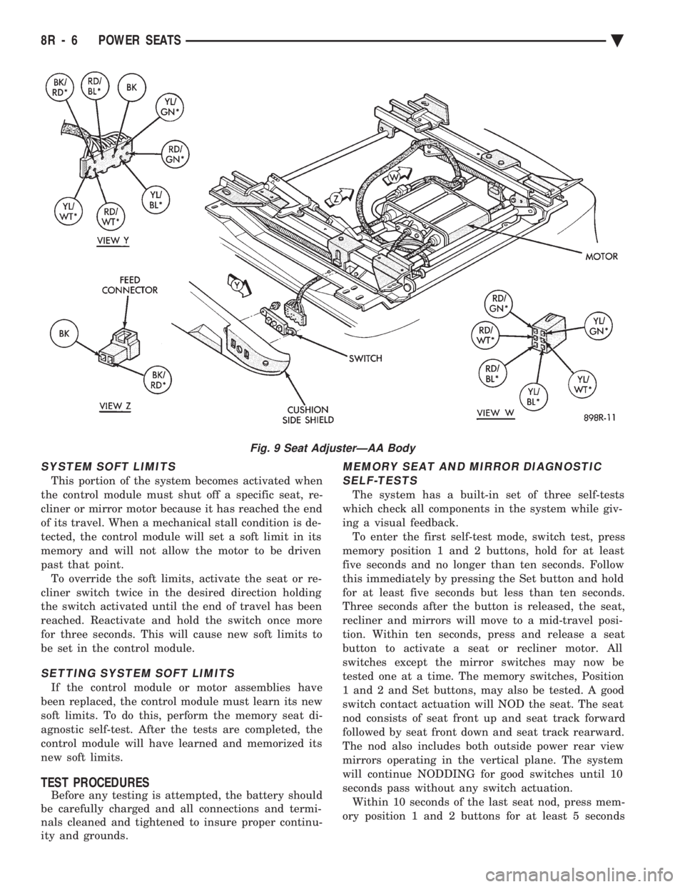
Fig. 9 Seat AdjusterÐAA Body
8R - 6 POWER SEATS Ä
Page 2165 of 2438
GUIDE ASSEMBLY INSTALLATION
(1) Install guide cable into rear of guide assembly.
(2) Install guide assembly at an angle so the rear
portion slips under finger clips at rear of module
housing. (3) Place cable in groove of cable holder.
(4) Install screws in track assembly.
(5) Install locators.
(6) Reverse removal operation.
WINDSHIELD
SAFETY PRECAUTIONS AND WARNINGS
WARNING: DO NOT OPERATE VEHICLE FOR AT
LEAST 24 HOURS AFTER WINDSHIELD INSTALLA-
TION. WINDSHIELD MAY NOT PERFORM PROPERLY
IN THE EVENT OF A COLLISION IF URETHANE AD-
HESIVE IS NOT SUFFICIENTLY CURED. REFER TO
MANUFACTURER OF URETHANE BEING USED FOR
CURING TIME SPECIFICATIONS. WHEN INSTALLING GLASS, DO NOT USE URE-
THANE ADHESIVE AFTER DATE ON PRODUCT HAS
EXPIRED. SAFETY AND QUALITY OF REPAIR
WOULD BE QUESTIONABLE. DO NOT USE URETHANE ADHESIVE OR PRIMER IN
CLOSED WORK AREA, PERSONAL INJURY CAN RE-
SULT. PROTECT SKIN FROM COMING IN CONTACT WITH
URETHANE, PERSONAL INJURY CAN RESULT. WEAR EYE AND HAND PROTECTION WHEN
WORKING WITH GLASS, PERSONAL INJURY CAN
RESULT.
CAUTION: Protect all painted or trimmed surfaces
from coming in contact with urethane or primers,
damage will result. Do not damage painted surfaces when removing
mouldings or cutting urethane around windshield.
It is difficult to salvage a windshield during the
removal operation. The windshield is part of the struc-
tural support for the roof. The urethane bonding used
to secure the windshield to the fence is difficult to cut
or clean from any surface. If the mouldings are set in
urethane, it would also be unlikely they could be
salvaged. Before removing the windshield, check the
availability of the windshield and mouldings from the
parts supplier.
WINDSHIELD REMOVAL
(1) Remove inside rear view mirror.
(2) Remove cowl cover.
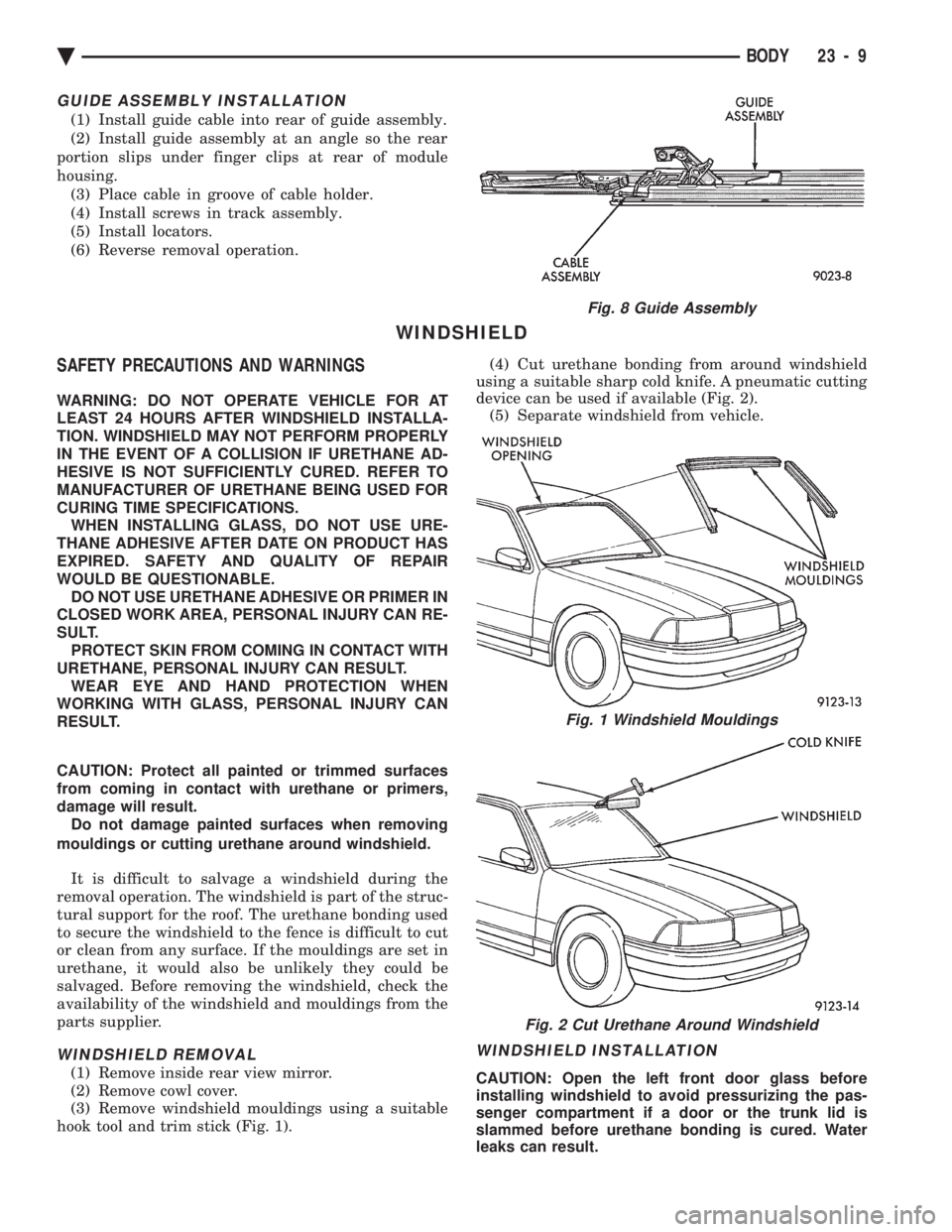
(3) Remove windshield mouldings using a suitable
hook tool and trim stick (Fig. 1). (4) Cut urethane bonding from around windshield
using a suitable sharp cold knife. A pneumatic cutting
device can be used if available (Fig. 2). (5) Separate windshield from vehicle.
WINDSHIELD INSTALLATION
CAUTION: Open the left front door glass before
installing windshield to avoid pressurizing the pas-
senger compartment if a door or the trunk lid is
slammed before urethane bonding is cured. Water
leaks can result.
Fig. 8 Guide Assembly
Fig. 1 Windshield Mouldings
Fig. 2 Cut Urethane Around Windshield
Ä BODY 23 - 9
Page 2166 of 2438
Allow the urethane at least 24 hours to cure before
returning the vehicle to use. The windshield fence should be cleaned of old ure-
thane bonding material. Support spacers should be
cleaned and properly installed on weld studs or re-
pair screws at bottom of windshield opening. (1) Place replacement windshield into windshield
opening and position glass in the center of the open-
ing against the support spacers. Mark the glass at
the support spacers with a grease pencil or pieces of
masking tape and ink pen to use as a reference for
installation. Remove replacement windshield from
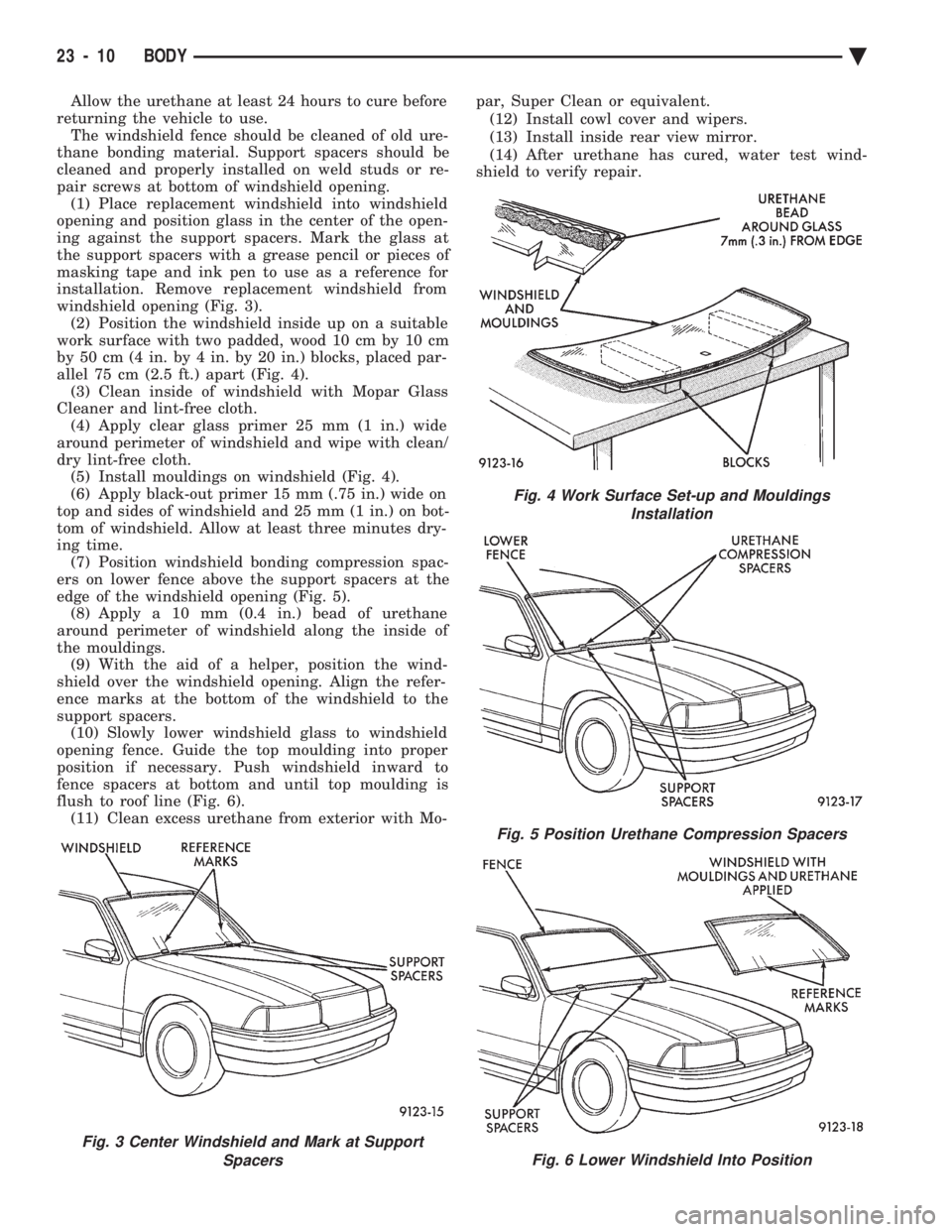
windshield opening (Fig. 3). (2) Position the windshield inside up on a suitable
work surface with two padded, wood 10 cm by 10 cm
by 50 cm (4 in. by 4 in. by 20 in.) blocks, placed par-
allel 75 cm (2.5 ft.) apart (Fig. 4). (3) Clean inside of windshield with Mopar Glass
Cleaner and lint-free cloth. (4) Apply clear glass primer 25 mm (1 in.) wide
around perimeter of windshield and wipe with clean/
dry lint-free cloth. (5) Install mouldings on windshield (Fig. 4).
(6) Apply black-out primer 15 mm (.75 in.) wide on
top and sides of windshield and 25 mm (1 in.) on bot-
tom of windshield. Allow at least three minutes dry-
ing time. (7) Position windshield bonding compression spac-
ers on lower fence above the support spacers at the
edge of the windshield opening (Fig. 5). (8) Apply a 10 mm (0.4 in.) bead of urethane
around perimeter of windshield along the inside of
the mouldings. (9) With the aid of a helper, position the wind-
shield over the windshield opening. Align the refer-
ence marks at the bottom of the windshield to the
support spacers. (10) Slowly lower windshield glass to windshield
opening fence. Guide the top moulding into proper
position if necessary. Push windshield inward to
fence spacers at bottom and until top moulding is
flush to roof line (Fig. 6). (11) Clean excess urethane from exterior with Mo- par, Super Clean or equivalent.
(12) Install cowl cover and wipers.
(13) Install inside rear view mirror.
(14) After urethane has cured, water test wind-
shield to verify repair.
Fig. 3 Center Windshield and Mark at Support
Spacers
Fig. 4 Work Surface Set-up and MouldingsInstallation
Fig. 5 Position Urethane Compression Spacers
Fig. 6 Lower Windshield Into Position
23 - 10 BODY Ä
Page 2167 of 2438
AA-VEHICLE BODY COMPONENT SERVICE INDEX
page page
A-Pillar and Roof Rail Mouldings ............. 25
B-Pillar Trim Panel ....................... 25
Body Side Moulding and Applique ............ 24
Cowl Cover ............................. 13
Cowl Panel Trim and Scuff Plates ............ 25
Door Opening Weatherstrips ................ 24
Floor Carpet ............................ 30
Front Center Console ..................... 29
Front Door and Hinge ..................... 15
Front Door Belt Moulding and Weatherstrip ..... 17
Front Door Glass ........................ 17
Front Door Glass Channel and Run Weatherstrip . 18
Front Door Glass Run Lower Channel ......... 18
Front Door Latch ......................... 16
Front Door Side View Mirror ................ 17
Front Door Silencer and Water Shield ......... 15
Front Door Trim Panel .................... 14
Front Door Window Regulator/Manual ......... 18
Front Door Window Regulator/Power .......... 19
Front End Splash Shields .................. 13
Front Fender ............................ 14
Front Power Door Lock Actuator ............. 19
Front Seat Belts ......................... 27
Front Seats ............................. 28
Fuel Fill Door ........................... 36
Grille .................................. 11
Head Lining ............................. 30
Hood and Hinges ........................ 11
Hood Latch and Release Cable .............. 12
Outside Front Door Latch Release Handle ..... 16
Outside Rear Door Latch Release Handle ...... 21 Overhead Console
........................ 30
Quarter Extension Trim Panel ............... 27
Quarter Trim Panel ....................... 27
Rear Deck Filler Panel .................... 31
Rear Door and Hinge ..................... 20
Rear Door Belt Moulding and Weatherstrip ..... 22
Rear Door Glass ......................... 22
Rear Door Glass Run Weatherstrip ........... 22
Rear Door Glass Stationary Glass Module ..... 23
Rear Door Latch ......................... 21
Rear Door Silencer and Water Shield ......... 20
Rear Door Trim Panel ..................... 20
Rear Door Window Regulator/Manual ......... 23
Rear Door Window Regulator/Power .......... 23
Rear Power Door Lock Actuator ............. 22
Rear Seat Belts .......................... 28
Rear Seats ............................. 28
Rear Shelf Trim Panel ..................... 27
Rear Window Glass ...................... 32
Sun Roof Air Deflector .................... 31
Sun Roof Drain Tubes .................... 31
Sun Roof Weatherstrip .................... 31
Trunk Lid .............................. 33
Trunk Lid Hinge ......................... 34
Trunk Lid Latch .......................... 34
Trunk Lid Lock .......................... 34
Trunk Lid Luggage Rack ................... 35
Trunk Lid Torsion Bar ..................... 34
Trunk Lining ............................ 35
Trunk Opening Weatherstrip ................ 35
Vinyl Roof Bonnet ........................ 31
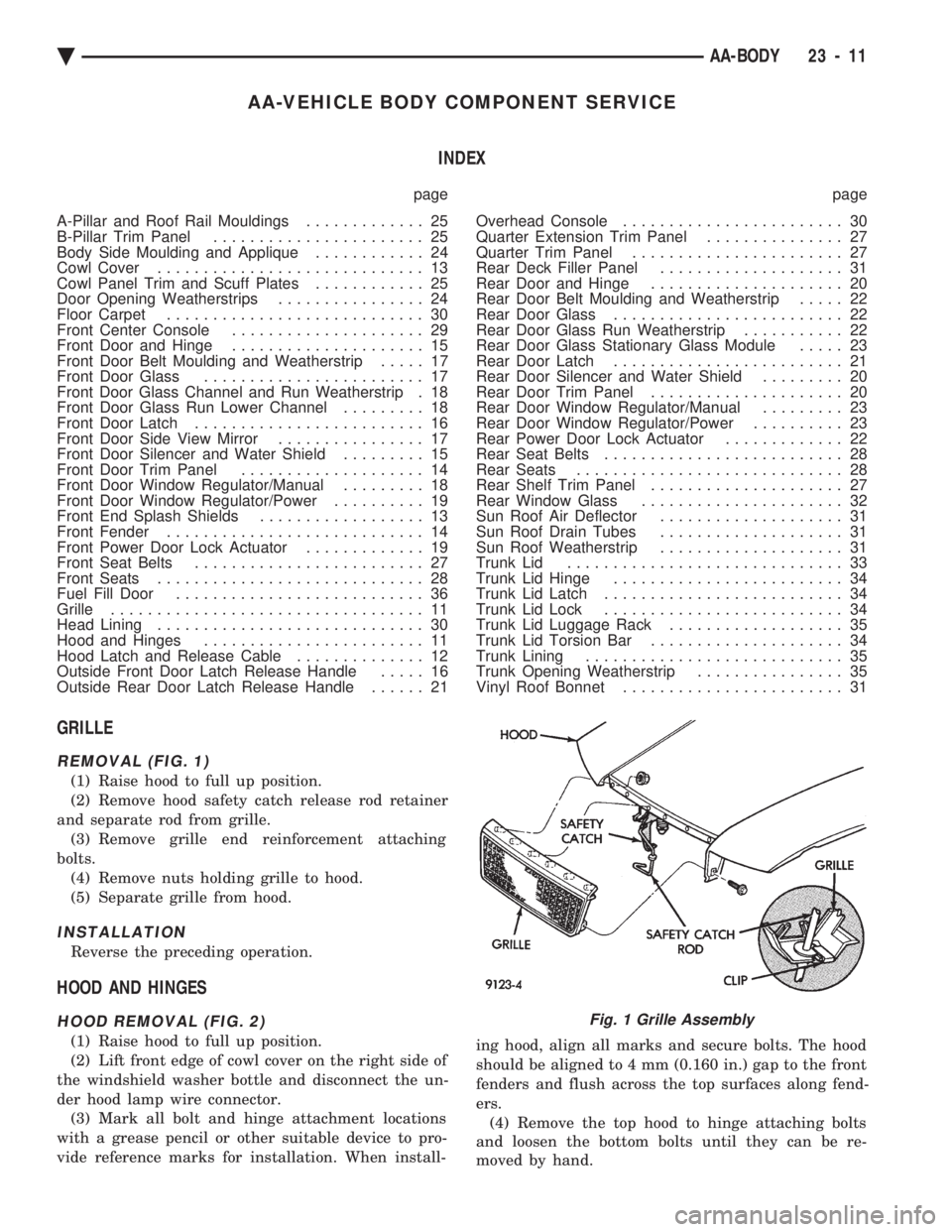
GRILLE
REMOVAL (FIG. 1)
(1) Raise hood to full up position.
(2) Remove hood safety catch release rod retainer
and separate rod from grille. (3) Remove grille end reinforcement attaching
bolts. (4) Remove nuts holding grille to hood.
(5) Separate grille from hood.
INSTALLATION
Reverse the preceding operation.
HOOD AND HINGES
HOOD REMOVAL (FIG. 2)
(1) Raise hood to full up position.
(2) Lift front edge of cowl cover on the right side of
the windshield washer bottle and disconnect the un-
der hood lamp wire connector. (3) Mark all bolt and hinge attachment locations
with a grease pencil or other suitable device to pro-
vide reference marks for installation. When install- ing hood, align all marks and secure bolts. The hood
should be aligned to 4 mm (0.160 in.) gap to the front
fenders and flush across the top surfaces along fend-
ers. (4) Remove the top hood to hinge attaching bolts
and loosen the bottom bolts until they can be re-
moved by hand.
Fig. 1 Grille Assembly
Ä AA-BODY 23 - 11
Page 2173 of 2438
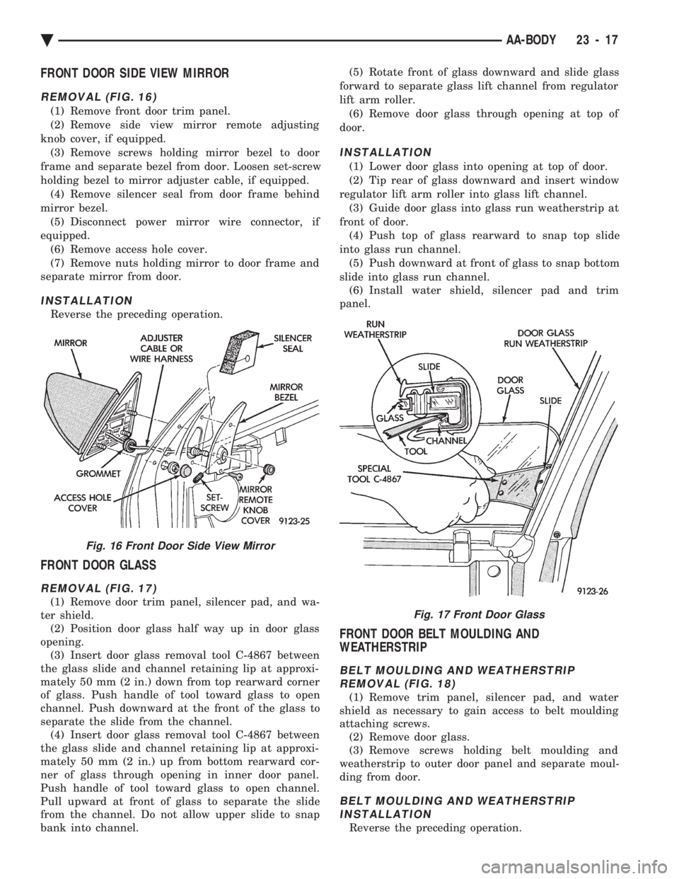
FRONT DOOR SIDE VIEW MIRROR
REMOVAL (FIG. 16)
(1) Remove front door trim panel.
(2) Remove side view mirror remote adjusting
knob cover, if equipped. (3) Remove screws holding mirror bezel to door
frame and separate bezel from door. Loosen set-screw
holding bezel to mirror adjuster cable, if equipped. (4) Remove silencer seal from door frame behind
mirror bezel. (5) Disconnect power mirror wire connector, if
equipped. (6) Remove access hole cover.
(7) Remove nuts holding mirror to door frame and
separate mirror from door.
INSTALLATION
Reverse the preceding operation.
FRONT DOOR GLASS
REMOVAL (FIG. 17)
(1) Remove door trim panel, silencer pad, and wa-
ter shield. (2) Position door glass half way up in door glass
opening. (3) Insert door glass removal tool C-4867 between
the glass slide and channel retaining lip at approxi-
mately 50 mm (2 in.) down from top rearward corner
of glass. Push handle of tool toward glass to open
channel. Push downward at the front of the glass to
separate the slide from the channel. (4) Insert door glass removal tool C-4867 between
the glass slide and channel retaining lip at approxi-
mately 50 mm (2 in.) up from bottom rearward cor-
ner of glass through opening in inner door panel.
Push handle of tool toward glass to open channel.
Pull upward at front of glass to separate the slide
from the channel. Do not allow upper slide to snap
bank into channel. (5) Rotate front of glass downward and slide glass
forward to separate glass lift channel from regulator
lift arm roller. (6) Remove door glass through opening at top of
door.
INSTALLATION
(1) Lower door glass into opening at top of door.
(2) Tip rear of glass downward and insert window
regulator lift arm roller into glass lift channel. (3) Guide door glass into glass run weatherstrip at
front of door. (4) Push top of glass rearward to snap top slide
into glass run channel. (5) Push downward at front of glass to snap bottom
slide into glass run channel. (6) Install water shield, silencer pad and trim
panel.
FRONT DOOR BELT MOULDING AND
WEATHERSTRIP
BELT MOULDING AND WEATHERSTRIP REMOVAL (FIG. 18)
(1) Remove trim panel, silencer pad, and water
shield as necessary to gain access to belt moulding
attaching screws. (2) Remove door glass.
(3) Remove screws holding belt moulding and
weatherstrip to outer door panel and separate moul-
ding from door.
BELT MOULDING AND WEATHERSTRIP INSTALLATION
Reverse the preceding operation.
Fig. 16 Front Door Side View Mirror
Fig. 17 Front Door Glass
Ä AA-BODY 23 - 17
Page 2186 of 2438
INSTALLATION
Reverse the preceding operation. On vehicles with
automatic transaxle, verify gear selector indicator
adjustment before returning vehicle to use.
FLOOR CARPET
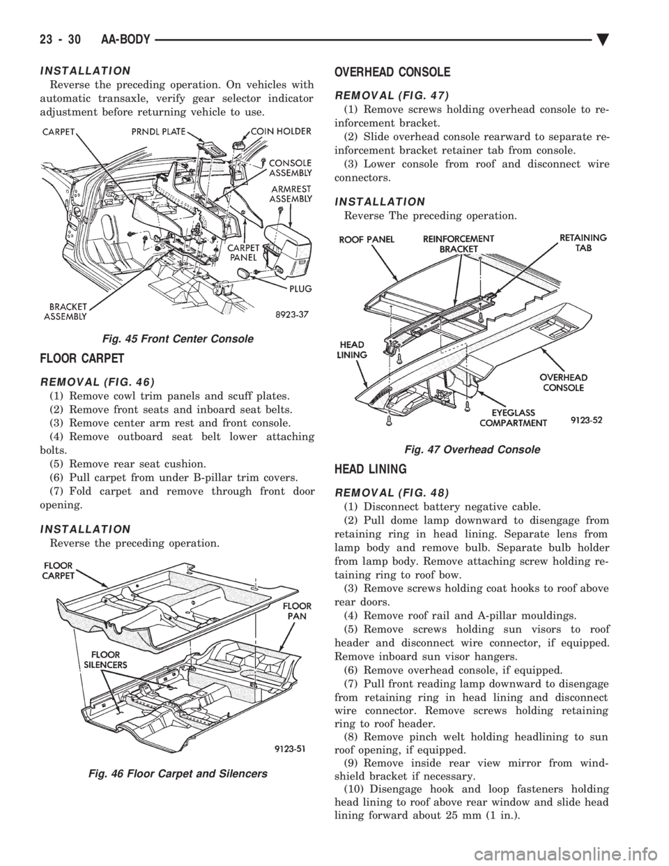
REMOVAL (FIG. 46)
(1) Remove cowl trim panels and scuff plates.
(2) Remove front seats and inboard seat belts.
(3) Remove center arm rest and front console.
(4) Remove outboard seat belt lower attaching
bolts. (5) Remove rear seat cushion.
(6) Pull carpet from under B-pillar trim covers.
(7) Fold carpet and remove through front door
opening.
INSTALLATION
Reverse the preceding operation.
OVERHEAD CONSOLE
REMOVAL (FIG. 47)
(1) Remove screws holding overhead console to re-
inforcement bracket. (2) Slide overhead console rearward to separate re-
inforcement bracket retainer tab from console. (3) Lower console from roof and disconnect wire
connectors.
INSTALLATION
Reverse The preceding operation.
HEAD LINING
REMOVAL (FIG. 48)
(1) Disconnect battery negative cable.
(2) Pull dome lamp downward to disengage from
retaining ring in head lining. Separate lens from
lamp body and remove bulb. Separate bulb holder
from lamp body. Remove attaching screw holding re-
taining ring to roof bow. (3) Remove screws holding coat hooks to roof above
rear doors. (4) Remove roof rail and A-pillar mouldings.
(5) Remove screws holding sun visors to roof
header and disconnect wire connector, if equipped.
Remove inboard sun visor hangers. (6) Remove overhead console, if equipped.
(7) Pull front reading lamp downward to disengage
from retaining ring in head lining and disconnect
wire connector. Remove screws holding retaining
ring to roof header. (8) Remove pinch welt holding headlining to sun
roof opening, if equipped. (9) Remove inside rear view mirror from wind-
shield bracket if necessary. (10) Disengage hook and loop fasteners holding
head lining to roof above rear window and slide head
lining forward about 25 mm (1 in.).
Fig. 45 Front Center Console
Fig. 46 Floor Carpet and Silencers
Fig. 47 Overhead Console
23 - 30 AA-BODY Ä