1993 CHEVROLET PLYMOUTH ACCLAIM rear view mirror
[x] Cancel search: rear view mirrorPage 2193 of 2438
AC-VEHICLE BODY COMPONENT SERVICE INDEX
page page
A-Pillar and Roof Rail Mouldings ............. 46
B-Pillar Trim Panel ....................... 46
Body Mouldings .......................... 49
Cowl Panel Trim and Scuff Plates ............ 46
Door Frame Trim Moulding ................. 41
Front Door and Hinge ..................... 41
Front Door Glass ........................ 43
Front Door Latch ......................... 42
Front Door Trim Panel .................... 40
Front Door Water Shield ................... 41
Front Door Window Regulator ............... 42
Front End Splash Shields .................. 40
Front Seat Belts ......................... 47
Front Seats ............................. 48
Grille AC/C Body ......................... 38
Grille AC/D or AC/C-H Body ................ 37
Grille Extension Moulding .................. 37
Grille Opening Panel AC/C-Body ............. 38
Grille Opening Panel AC/D and AC/C-H Body . . . 37
Head Lining ............................. 45
Hood and Hinges ........................ 38
Hood Latch and Release Cable .............. 39
Hood Latch Release Cable ................. 39 Hood Ornament AC/C
..................... 38
Outside Door Handle ...................... 42
Overhead Console ........................ 45
Quarter Trim Panel ....................... 46
Rear Deck Filler Panel .................... 49
Rear Door and Hinge ..................... 44
Rear Door Frame Trim Moulding ............. 43
Rear Door Glass ......................... 45
Rear Door Glass Lift Plate and Guide Bar ..... 45
Rear Door Latch ......................... 44
Rear Door Outside Handle ................. 44
Rear Door Silencer and Water Shield ......... 43
Rear Door Trim Panel ..................... 43
Rear Door Window Regulator ............... 45
Rear Seat Belts .......................... 47
Rear Seats ............................. 49
Rear Shelf Trim Panel ..................... 47
Rear Window Glass ...................... 50
Side View Mirror Trim Cover ................ 41
Trunk Lid .............................. 50
Trunk Lid Hinge ......................... 51
Trunk Lid Torsion Bar ..................... 51
Vinyl Roof Bonnet ........................ 49
GRILLE AC/D or AC/C-H BODY
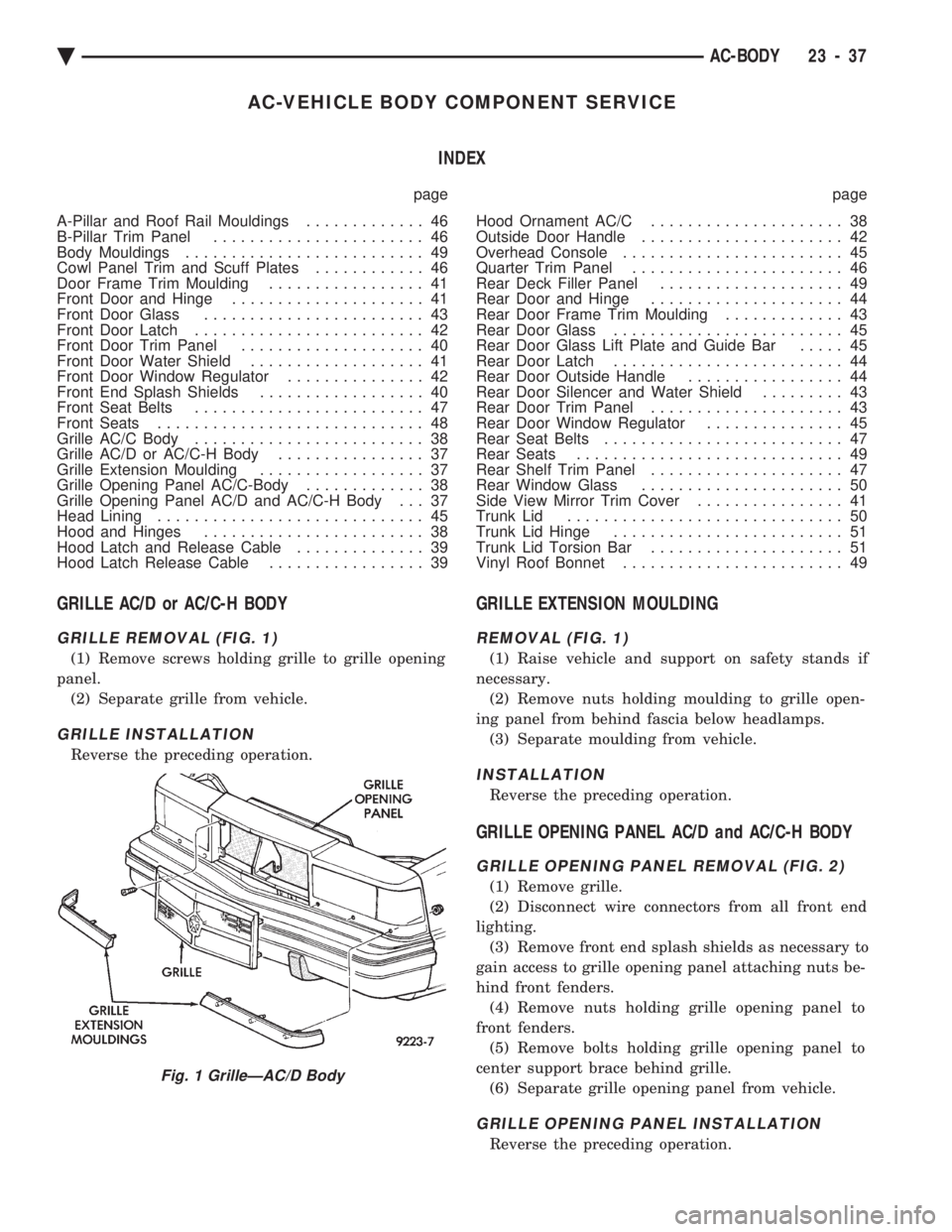
GRILLE REMOVAL (FIG. 1)
(1) Remove screws holding grille to grille opening
panel. (2) Separate grille from vehicle.
GRILLE INSTALLATION
Reverse the preceding operation.
GRILLE EXTENSION MOULDING
REMOVAL (FIG. 1)
(1) Raise vehicle and support on safety stands if
necessary. (2) Remove nuts holding moulding to grille open-
ing panel from behind fascia below headlamps. (3) Separate moulding from vehicle.
INSTALLATION
Reverse the preceding operation.
GRILLE OPENING PANEL AC/D and AC/C-H BODY
GRILLE OPENING PANEL REMOVAL (FIG. 2)
(1) Remove grille.
(2) Disconnect wire connectors from all front end
lighting. (3) Remove front end splash shields as necessary to
gain access to grille opening panel attaching nuts be-
hind front fenders. (4) Remove nuts holding grille opening panel to
front fenders. (5) Remove bolts holding grille opening panel to
center support brace behind grille. (6) Separate grille opening panel from vehicle.
GRILLE OPENING PANEL INSTALLATION
Reverse the preceding operation.
Fig. 1 GrilleÐAC/D Body
Ä AC-BODY 23 - 37
Page 2199 of 2438
(4) Remove door glass.
(5) Remove nut holding cable retainer to inner
door panel and slip cables from behind retainer. (6) Disengage push in retainer holding cables to
inner door panel above speaker on vehicles with
power windows. (7) Remove bolts holding top of glass lift bar to in-
ner door panel. (8) Remove nut holding bottom of lift bar to bot-
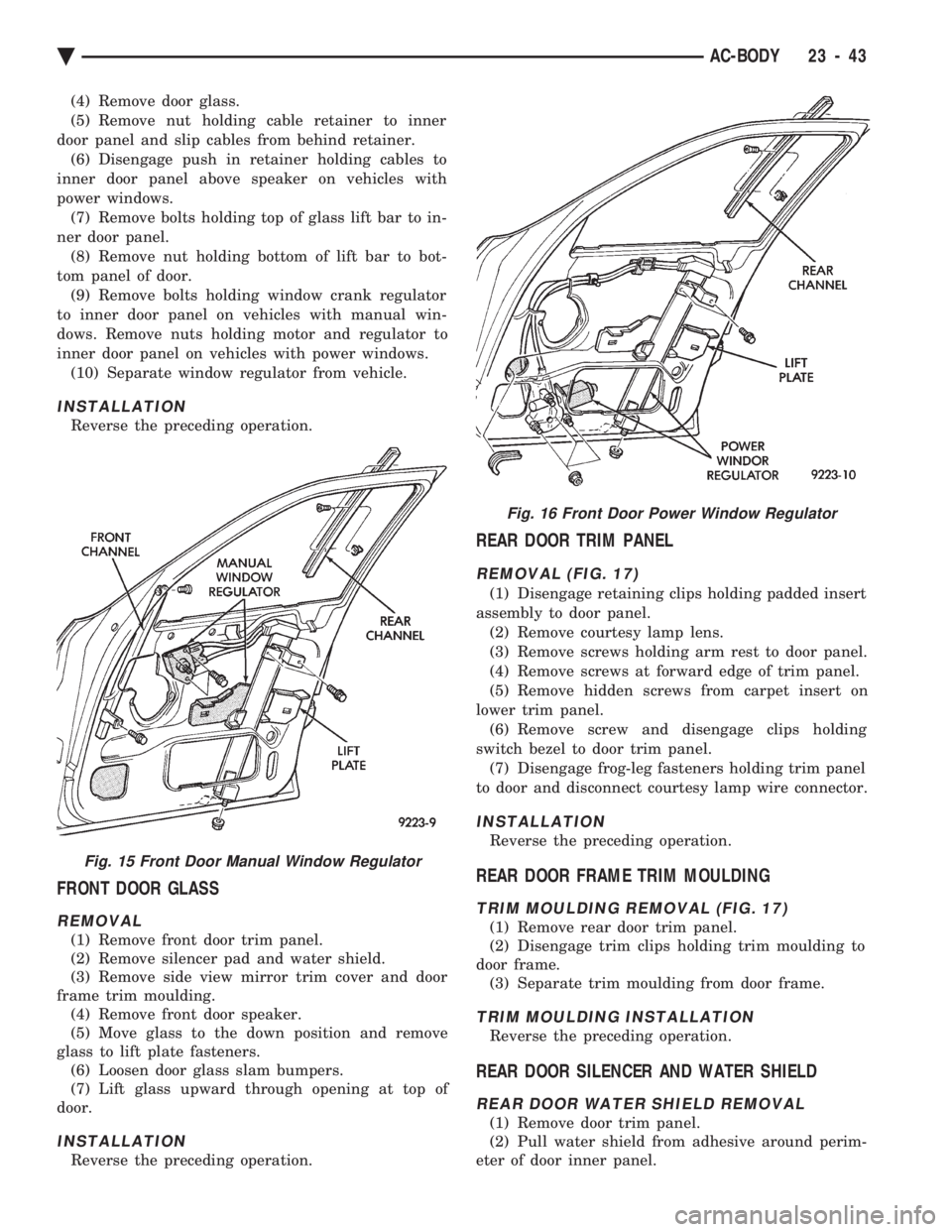
tom panel of door. (9) Remove bolts holding window crank regulator
to inner door panel on vehicles with manual win-
dows. Remove nuts holding motor and regulator to
inner door panel on vehicles with power windows. (10) Separate window regulator from vehicle.
INSTALLATION
Reverse the preceding operation.
FRONT DOOR GLASS
REMOVAL
(1) Remove front door trim panel.
(2) Remove silencer pad and water shield.
(3) Remove side view mirror trim cover and door
frame trim moulding. (4) Remove front door speaker.
(5) Move glass to the down position and remove
glass to lift plate fasteners. (6) Loosen door glass slam bumpers.
(7) Lift glass upward through opening at top of
door.
INSTALLATION
Reverse the preceding operation.
REAR DOOR TRIM PANEL
REMOVAL (FIG. 17)
(1) Disengage retaining clips holding padded insert
assembly to door panel. (2) Remove courtesy lamp lens.
(3) Remove screws holding arm rest to door panel.
(4) Remove screws at forward edge of trim panel.
(5) Remove hidden screws from carpet insert on
lower trim panel. (6) Remove screw and disengage clips holding
switch bezel to door trim panel. (7) Disengage frog-leg fasteners holding trim panel
to door and disconnect courtesy lamp wire connector.
INSTALLATION
Reverse the preceding operation.
REAR DOOR FRAME TRIM MOULDING
TRIM MOULDING REMOVAL (FIG. 17)
(1) Remove rear door trim panel.
(2) Disengage trim clips holding trim moulding to
door frame. (3) Separate trim moulding from door frame.
TRIM MOULDING INSTALLATION
Reverse the preceding operation.
REAR DOOR SILENCER AND WATER SHIELD
REAR DOOR WATER SHIELD REMOVAL
(1) Remove door trim panel.
(2) Pull water shield from adhesive around perim-
eter of door inner panel.
Fig. 15 Front Door Manual Window Regulator
Fig. 16 Front Door Power Window Regulator
Ä AC-BODY 23 - 43
Page 2202 of 2438
(7) Pull front reading lamp downward to disengage
from retaining ring in head lining and disconnect
wire connector. Remove screws holding retaining
ring to roof header. (8) Remove pinch welt holding headlining to sun
roof opening, if equipped. (9) Remove inside rear view mirror from wind-
shield bracket, if necessary. (10) Disengage hook and loop fasteners holding
head lining to roof above rear window and slide head
lining forward about 25 mm (1 in.). (11) Shift the front of head lining to one side to
pull head lining from behind B-pillar trim. Pull head
lining from behind other B-pillar trim. (12) Allow front of head lining to drop downward.
Slide head lining forward from behind quarter panel
trim. (13) Remove head lining from vehicle.
INSTALLATION
Reverse the preceding operation.
COWL PANEL TRIM AND SCUFF PLATES
COWL PANEL AND DOOR OPENING SCUFFPLATE REMOVAL (FIG. 22)
(1) Open front door.
(2) Remove screw holding trim panel to cowl for-
ward of the front door opening. (3) Remove screws holding scuff plate to door sill.
(4) Separate cowl panel trim and scuff plate from
vehicle.
COWL PANEL AND DOOR OPENING SCUFF PLATE INSTALLATION
Reverse the preceding operation.
REAR DOOR OPENING SCUFF PLATEREMOVAL (FIG. 22)
(1) Open rear door.
(2) Remove screws holding scuff plate to door sill.
(3) Separate scuff plate from vehicle.
REAR DOOR OPENING SCUFF PLATE INSTALLATION
Reverse the preceding operation.
A-PILLAR AND ROOF RAIL MOULDINGS
A-PILLAR MOULDING REMOVAL (FIG. 22)
(1) Open front door.
(2) Disengage clips holding A-pillar moulding to
roof rail above door opening. (3) Slide A-pillar moulding upward and pull rear-
ward to separate moulding from A-pillar.
A-PILLAR MOULDING INSTALLATION
Reverse the preceding operation.
REAR DOOR ROOF RAIL MOULDING REMOVAL (FIG. 22)
(1) Open rear door.
(2) Disengage clips holding roof rail moulding to
roof rail above rear door opening. (3) Separate moulding from vehicle.
REAR DOOR ROOF RAIL MOULDINGINSTALLATION
Reverse the preceding operation.
B-PILLAR TRIM PANEL
REMOVAL (FIG. 22)
(1) Remove roof rail mouldings and scuff plates as
necessary. (2) Remove shoulder harness turning loop cover.
Remove bolt holding turning loop to B-pillar. (3) Remove bolt holding seat belt to floor below
B-pillar. (4) Remove upper B-pillar trim.
(5) Remove lower B-pillar trim.
INSTALLATION
Reverse the preceding operation.
QUARTER TRIM PANEL
REMOVAL (FIG. 22)
(1) Remove rear roof rail mouldings and scuff
plates as necessary.
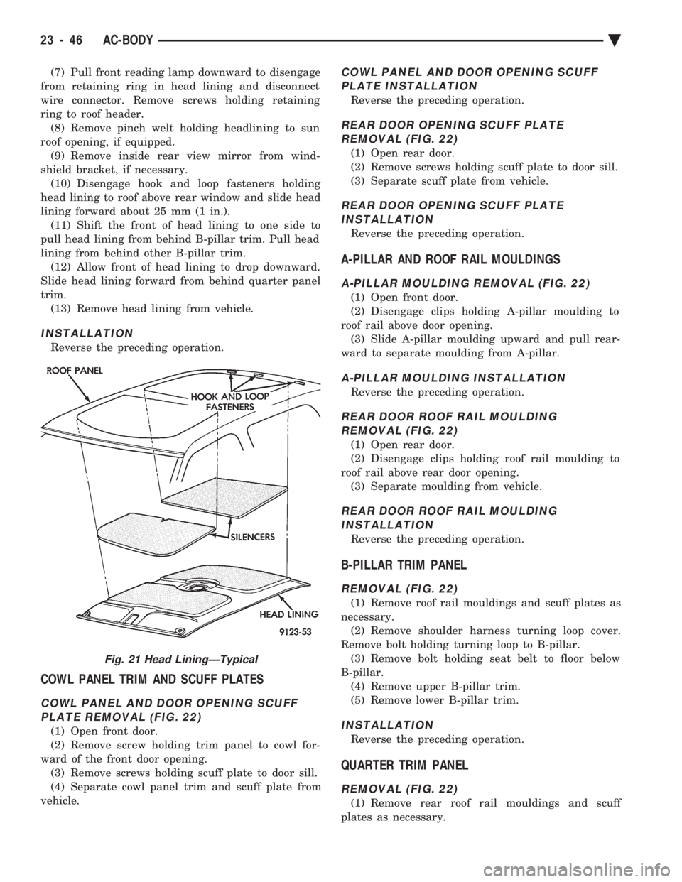
Fig. 21 Head LiningÐTypical
23 - 46 AC-BODY Ä
Page 2208 of 2438
AG-VEHICLE BODY COMPONENT SERVICE INDEX
page page
A-Pillar and Roof Rail Mouldings ............. 61
Body Side Applique ....................... 60
Body Side Mouldings ...................... 60
Closure Panel Sight Shield ................. 52
Cowl Cover ............................. 54
Door Glass ............................. 58
Door Glass Opening Moulding ............... 59
Door Latch ............................. 57
Door Opening Scuff Plates ................. 61
Door Opening Weatherstrips ................ 60
Door Trim Panel ......................... 56
Floor Carpet ............................ 64
Front Center Console ..................... 64
Front Door and Hinge ..................... 56
Front Door Silencer and Water Shield ......... 56
Front End Splash Shields .................. 54
Front Fender ............................ 55
Front Seat Belts ......................... 61
Front Seats ............................. 63
Fuel Fill Door ........................... 68
Glass Run Weatherstrip ................... 58
Head Lining ............................. 65
Hood and Hinges ........................ 52
Hood Applique .......................... 54
Hood Latch and Release Cable .............. 53
Hood Latch Safety Catch .................. 54
Inside Latch Release Handle ................ 59 Lift Gate
............................... 67
Lift Gate and Fuel Fill Door Release Cables .... 69
Lift Gate Latch and Striker ................. 68
Lift Gate Lock Cylinder .................... 68
Lift Gate Prop Cylinder .................... 67
Lift Gate Spoiler ......................... 67
Lift Gate Trim ........................... 61
Lower Quarter Trim Panel .................. 61
Lower Tail Panel Trim Cover ................ 61
Manual Window Lift Plate and Guide .......... 58
Manual Window Regulator .................. 57
Manual Window Regulator .................. 58
Outside Door Latch Release Handle .......... 58
Overhead Console ........................ 65
Power Door Lock Actuator .................. 59
Power Window Regulator .................. 57
Quarter Glass Module ..................... 66
Quarter Panel Spoiler ..................... 67
Rear Seat Belts .......................... 62
Rear Seats ............................. 63
Rear Window Glass ...................... 65
Roof Seam Molding ....................... 66
Side View Mirror ......................... 59
Sunroof Lift Control ....................... 65
Tail Lamp Closure Panel ................... 69
Upper Quarter Trim Panel .................. 61
CLOSURE PANEL SIGHT SHIELD
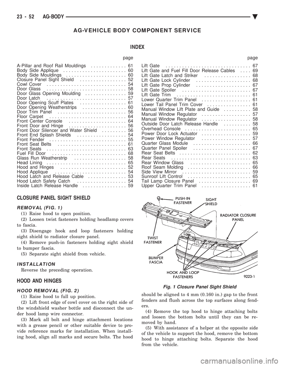
REMOVAL (FIG. 1)
(1) Raise hood to open position.
(2) Loosen twist fasteners holding headlamp covers
to fascia. (3) Disengage hook and loop fasteners holding
sight shield to radiator closure panel. (4) Remove push-in fasteners holding sight shield
to bumper fascia. (5) Separate sight shield from vehicle.
INSTALLATION
Reverse the preceding operation.
HOOD AND HINGES
HOOD REMOVAL (FIG. 2)
(1) Raise hood to full up position.
(2) Lift front edge of cowl cover on the right side of
the windshield washer bottle and disconnect the un-
der hood lamp wire connector. (3) Mark all bolt and hinge attachment locations
with a grease pencil or other suitable device to pro-
vide reference marks for installation. When install-
ing hood, align all marks and secure bolts. The hood should be aligned to 4 mm (0.160 in.) gap to the front
fenders and flush across the top surfaces along fend-
ers. (4) Remove the top hood to hinge attaching bolts
and loosen the bottom bolts until they can be re-
moved by hand. (5) With assistance of a helper at the opposite side
of the vehicle to support the hood, remove the bottom
hood to hinge attaching bolts. Separate the hood
from the vehicle.
Fig. 1 Closure Panel Sight Shield
23 - 52 AG-BODY Ä
Page 2253 of 2438
AP-VEHICLE BODY COMPONENT SERVICE INDEX
page page
A-Pillar and Roof Rail Mouldings ............ 109
B-Pillar Trim PanelÐAP-44 Body ............ 109
Body Side Moulding and Applique ........... 108
Cowl Panel Trim and Scuff Plates ........... 109
Door Opening Weatherstrips ............... 107
Floor Carpet ........................... 113
Front Center Console .................... 113
Front Door and Hinge .................... 100
Front Door Belt Moulding and Weatherstrip .... 102
Front Door Glass ........................ 101
Front Door Glass Channel and Run Weatherstrip .......................... 103
Front Door Glass Run Lower Channels ....... 103
Front Door Latch ........................ 101
Front Door Side View Mirror ............... 101
Front Door Trim PanelÐAP-24/44 Body ....... 99
Front Door Water Shield .................. 100
Front Door Window Regulator/Manual ........ 103
Front Door Window Regulator/Power ......... 104
Front End Splash Shields .................. 99
Front Power Door Lock Actuator ............ 102
Front Seat BeltsÐAP-24 Body .............. 110
Front Seat BeltsÐAP-44 Body .............. 110
Front Seats ............................ 111
Grille .................................. 97
Grille Opening Panel ...................... 97
Head Lining ............................ 114
Hood and Hinges ........................ 97 Hood Latch and Release Cable
.............. 98
Lift Gate Luggage Rack ................... 116
Lift Gate Remote Release Cable ............ 115
Lower Quarter Trim PanelÐAP-44 Body ...... 109
Outside Front Door Latch Release Handle ..... 101
Outside Rear Door Latch Release Handle ..... 105
Overhead Console ....................... 113
Quarter Glass Weatherstrip ................ 108
Quarter Glass Window ................... 108
Quarter Trim PanelÐAP-44 Body ........... 109
Rear Door and Hinge .................... 104
Rear Door Belt Moulding and Weatherstrip .... 106
Rear Door Glass ........................ 106
Rear Door Glass Run Weatherstrip .......... 107
Rear Door Latch ........................ 105
Rear Door Silencer and Water Shield ........ 104
Rear Door Stationary Glass ................ 107
Rear Door Trim Panel .................... 104
Rear Door Window Regulator/Manual ........ 107
Rear Door Window Regulator/Power ......... 107
Rear Power Door Lock Actuator ............ 106
Rear Seat Belts ......................... 111
Rear Seats ............................ 112
Rear Window Glass ...................... 115
Sun Roof Air Deflector ................... 114
Sun Roof Drain Tubes .................... 115
Sun Roof Weatherstrip ................... 114
Upper Quarter Trim PanelÐAP-44 Body ...... 109
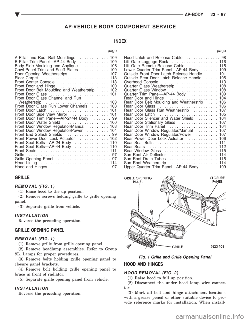
GRILLE
REMOVAL (FIG. 1)
(1) Raise hood to the up position.
(2) Remove screws holding grille to grille opening
panel. (3) Separate grille from vehicle.
INSTALLATION
Reverse the preceding operation.
GRILLE OPENING PANEL
REMOVAL (FIG. 1)
(1) Remove grille from grille opening panel.
(2) Remove headlamp assemblies. Refer to Group
8L. Lamps for proper procedures. (3) Remove bolts holding grille opening panel to
closure panel brackets. (4) Remove bolt holding grille opening panel to
brace in front of radiator. (5) Separate grille opening panel from vehicle.
INSTALLATION
Reverse the preceding operation.
HOOD AND HINGES
HOOD REMOVAL (FIG. 2)
(1) Raise hood to full up position.
(2) Disconnect the under hood lamp wire connec-
tor. (3) Mark all bolt and hinge attachment locations
with a grease pencil or other suitable device to pro-
vide reference marks for installation. When install-
Fig. 1 Grille and Grille Opening Panel
Ä AP-BODY 23 - 97
Page 2257 of 2438
FRONT DOOR HINGE INSTALLATION
Reverse the preceding operation. Align door to
achieve 6 mm (0.240 in.) gap to all surrounding pan-
els and flush across gaps.
OUTSIDE FRONT DOOR LATCH RELEASE HANDLE
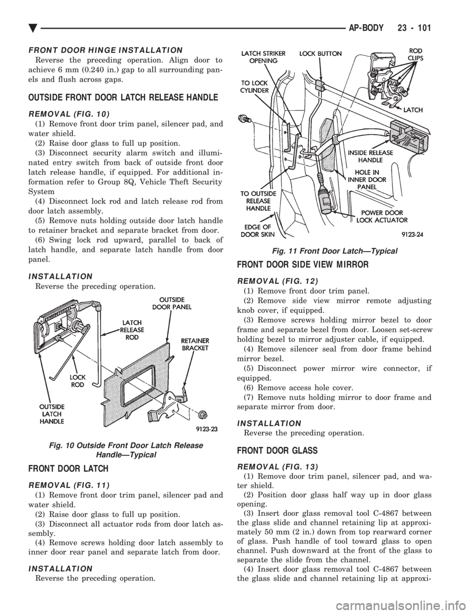
REMOVAL (FIG. 10)
(1) Remove front door trim panel, silencer pad, and
water shield. (2) Raise door glass to full up position.
(3) Disconnect security alarm switch and illumi-
nated entry switch from back of outside front door
latch release handle, if equipped. For additional in-
formation refer to Group 8Q, Vehicle Theft Security
System (4) Disconnect lock rod and latch release rod from
door latch assembly. (5) Remove nuts holding outside door latch handle
to retainer bracket and separate bracket from door. (6) Swing lock rod upward, parallel to back of
latch handle, and separate latch handle from door
panel.
INSTALLATION
Reverse the preceding operation.
FRONT DOOR LATCH
REMOVAL (FIG. 11)
(1) Remove front door trim panel, silencer pad and
water shield. (2) Raise door glass to full up position.
(3) Disconnect all actuator rods from door latch as-
sembly. (4) Remove screws holding door latch assembly to
inner door rear panel and separate latch from door.
INSTALLATION
Reverse the preceding operation.
FRONT DOOR SIDE VIEW MIRROR
REMOVAL (FIG. 12)
(1) Remove front door trim panel.
(2) Remove side view mirror remote adjusting
knob cover, if equipped. (3) Remove screws holding mirror bezel to door
frame and separate bezel from door. Loosen set-screw
holding bezel to mirror adjuster cable, if equipped. (4) Remove silencer seal from door frame behind
mirror bezel. (5) Disconnect power mirror wire connector, if
equipped. (6) Remove access hole cover.
(7) Remove nuts holding mirror to door frame and
separate mirror from door.
INSTALLATION
Reverse the preceding operation.
FRONT DOOR GLASS
REMOVAL (FIG. 13)
(1) Remove door trim panel, silencer pad, and wa-
ter shield. (2) Position door glass half way up in door glass
opening. (3) Insert door glass removal tool C-4867 between
the glass slide and channel retaining lip at approxi-
mately 50 mm (2 in.) down from top rearward corner
of glass. Push handle of tool toward glass to open
channel. Push downward at the front of the glass to
separate the slide from the channel. (4) Insert door glass removal tool C-4867 between
the glass slide and channel retaining lip at approxi-
Fig. 10 Outside Front Door Latch Release HandleÐTypical
Fig. 11 Front Door LatchÐTypical
Ä AP-BODY 23 - 101
Page 2258 of 2438
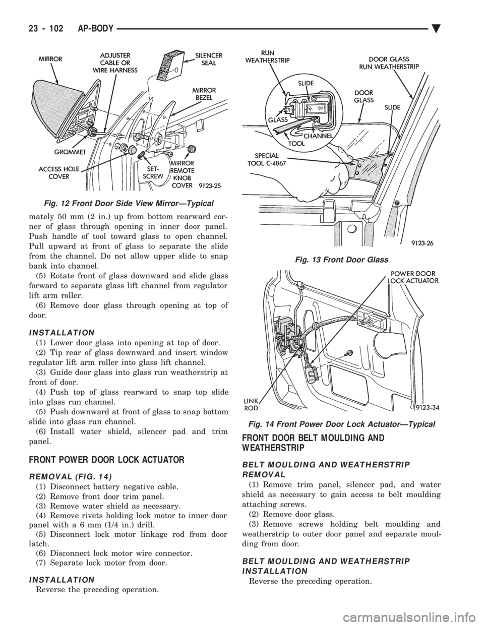
mately 50 mm (2 in.) up from bottom rearward cor-
ner of glass through opening in inner door panel.
Push handle of tool toward glass to open channel.
Pull upward at front of glass to separate the slide
from the channel. Do not allow upper slide to snap
bank into channel. (5) Rotate front of glass downward and slide glass
forward to separate glass lift channel from regulator
lift arm roller. (6) Remove door glass through opening at top of
door.
INSTALLATION
(1) Lower door glass into opening at top of door.
(2) Tip rear of glass downward and insert window
regulator lift arm roller into glass lift channel. (3) Guide door glass into glass run weatherstrip at
front of door. (4) Push top of glass rearward to snap top slide
into glass run channel. (5) Push downward at front of glass to snap bottom
slide into glass run channel. (6) Install water shield, silencer pad and trim
panel.
FRONT POWER DOOR LOCK ACTUATOR
REMOVAL (FIG. 14)
(1) Disconnect battery negative cable.
(2) Remove front door trim panel.
(3) Remove water shield as necessary.
(4) Remove rivets holding lock motor to inner door
panel wit ha6mm (1/4 in.) drill.
(5) Disconnect lock motor linkage rod from door
latch. (6) Disconnect lock motor wire connector.
(7) Separate lock motor from door.
INSTALLATION
Reverse the preceding operation.
FRONT DOOR BELT MOULDING AND
WEATHERSTRIP
BELT MOULDING AND WEATHERSTRIP
REMOVAL
(1) Remove trim panel, silencer pad, and water
shield as necessary to gain access to belt moulding
attaching screws. (2) Remove door glass.
(3) Remove screws holding belt moulding and
weatherstrip to outer door panel and separate moul-
ding from door.
BELT MOULDING AND WEATHERSTRIP INSTALLATION
Reverse the preceding operation.
Fig. 12 Front Door Side View MirrorÐTypical
Fig. 13 Front Door Glass
Fig. 14 Front Power Door Lock ActuatorÐTypical
23 - 102 AP-BODY Ä
Page 2270 of 2438
INSTALLATION
Reverse The preceding operation.
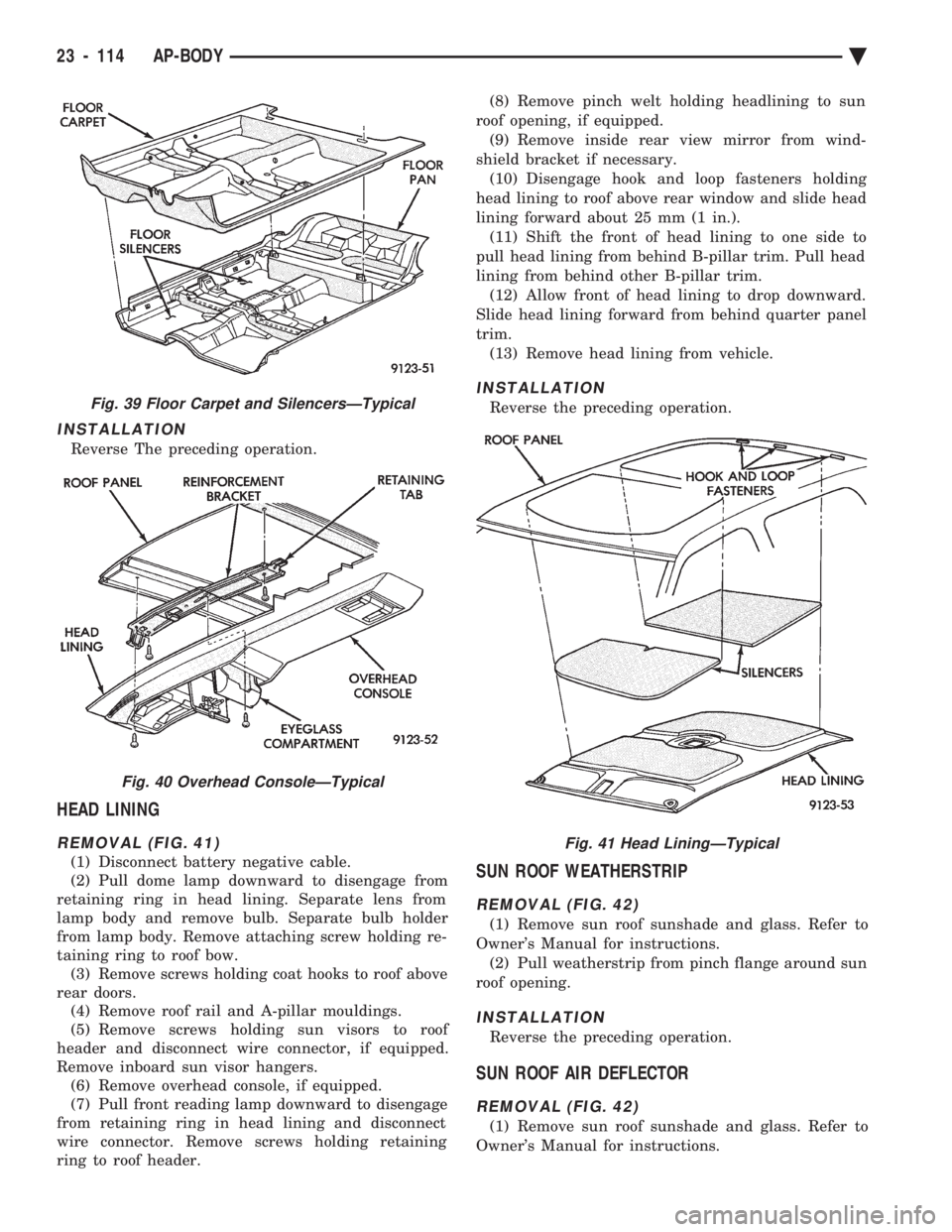
HEAD LINING
REMOVAL (FIG. 41)
(1) Disconnect battery negative cable.
(2) Pull dome lamp downward to disengage from
retaining ring in head lining. Separate lens from
lamp body and remove bulb. Separate bulb holder
from lamp body. Remove attaching screw holding re-
taining ring to roof bow. (3) Remove screws holding coat hooks to roof above
rear doors. (4) Remove roof rail and A-pillar mouldings.
(5) Remove screws holding sun visors to roof
header and disconnect wire connector, if equipped.
Remove inboard sun visor hangers. (6) Remove overhead console, if equipped.
(7) Pull front reading lamp downward to disengage
from retaining ring in head lining and disconnect
wire connector. Remove screws holding retaining
ring to roof header. (8) Remove pinch welt holding headlining to sun
roof opening, if equipped. (9) Remove inside rear view mirror from wind-
shield bracket if necessary. (10) Disengage hook and loop fasteners holding
head lining to roof above rear window and slide head
lining forward about 25 mm (1 in.). (11) Shift the front of head lining to one side to
pull head lining from behind B-pillar trim. Pull head
lining from behind other B-pillar trim. (12) Allow front of head lining to drop downward.
Slide head lining forward from behind quarter panel
trim. (13) Remove head lining from vehicle.
INSTALLATION
Reverse the preceding operation.
SUN ROOF WEATHERSTRIP
REMOVAL (FIG. 42)
(1) Remove sun roof sunshade and glass. Refer to
Owner's Manual for instructions. (2) Pull weatherstrip from pinch flange around sun
roof opening.
INSTALLATION
Reverse the preceding operation.
SUN ROOF AIR DEFLECTOR
REMOVAL (FIG. 42)
(1) Remove sun roof sunshade and glass. Refer to
Owner's Manual for instructions.
Fig. 39 Floor Carpet and SilencersÐTypical
Fig. 40 Overhead ConsoleÐTypical
Fig. 41 Head LiningÐTypical
23 - 114 AP-BODY Ä