1993 CHEVROLET PLYMOUTH ACCLAIM heater
[x] Cancel search: heaterPage 31 of 2438
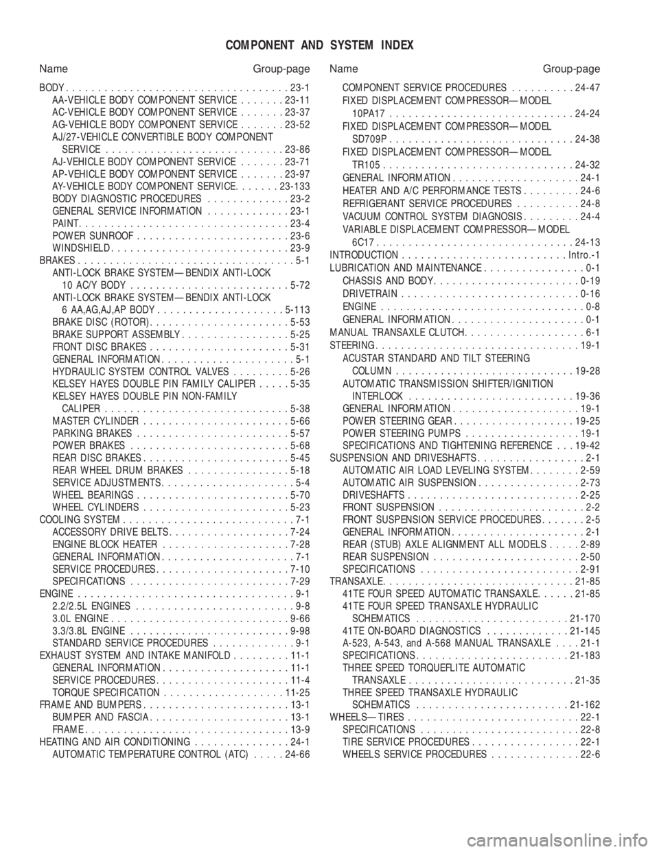
COMPONENT AND SYSTEM INDEX
Name Group-page Name Group-page
BODY ................................... 23-1
AA-VEHICLE BODY COMPONENT SERVICE .......23-11
AC-VEHICLE BODY COMPONENT SERVICE .......23-37
AG-VEHICLE BODY COMPONENT SERVICE .......23-52
AJ/27-VEHICLE CONVERTIBLE BODY COMPONENT SERVICE ............................ 23-86
AJ-VEHICLE BODY COMPONENT SERVICE .......23-71
AP-VEHICLE BODY COMPONENT SERVICE .......23-97
AY-VEHICLE BODY COMPONENT SERVICE .......23-133
BODY DIAGNOSTIC PROCEDURES .............23-2
GENERAL SERVICE INFORMATION .............23-1
PAINT ................................. 23-4
POWER SUNROOF ........................ 23-6
WINDSHIELD ............................ 23-9
BRAKES ..................................5-1
ANTI-LOCK BRAKE SYSTEMÐBENDIX ANTI-LOCK 10 AC/Y BODY ......................... 5-72
ANTI-LOCK BRAKE SYSTEMÐBENDIX ANTI-LOCK 6 AA,AG,AJ,AP BODY .................... 5-113
BRAKE DISC (ROTOR) ...................... 5-53
BRAKE SUPPORT ASSEMBLY .................5-25
FRONT DISC BRAKES ...................... 5-31
GENERAL INFORMATION .....................5-1
HYDRAULIC SYSTEM CONTROL VALVES .........5-26
KELSEY HAYES DOUBLE PIN FAMILY CALIPER .....5-35
KELSEY HAYES DOUBLE PIN NON-FAMILY CALIPER ............................. 5-38
MASTER CYLINDER ....................... 5-66
PARKING BRAKES ........................ 5-57
POWER BRAKES ......................... 5-68
REAR DISC BRAKES ....................... 5-45
REAR WHEEL DRUM BRAKES ................5-18
SERVICE ADJUSTMENTS .....................5-4
WHEEL BEARINGS ........................ 5-70
WHEEL CYLINDERS ....................... 5-23
COOLING SYSTEM ...........................7-1
ACCESSORY DRIVE BELTS ................... 7-24
ENGINE BLOCK HEATER .................... 7-28
GENERAL INFORMATION .....................7-1
SERVICE PROCEDURES ..................... 7-10
SPECIFICATIONS ......................... 7-29
ENGINE ..................................9-1
2.2/2.5L ENGINES .........................9-8
3.0L ENGINE ............................ 9-66
3.3/3.8L ENGINE ......................... 9-98
STANDARD SERVICE PROCEDURES .............9-1
EXHAUST SYSTEM AND INTAKE MANIFOLD .........11-1
GENERAL INFORMATION .................... 11-1
SERVICE PROCEDURES ..................... 11-4
TORQUE SPECIFICATION ................... 11-25
FRAME AND BUMPERS ....................... 13-1
BUMPER AND FASCIA ...................... 13-1
FRAME ................................ 13-9
HEATING AND AIR CONDITIONING ...............24-1
AUTOMATIC TEMPERATURE CONTROL (ATC) .....24-66 COMPONENT SERVICE PROCEDURES
..........24-47
FIXED DISPLACEMENT COMPRESSORÐMODEL 10PA17............................. 24-24
FIXED DISPLACEMENT COMPRESSORÐMODEL SD709P ............................. 24-38
FIXED DISPLACEMENT COMPRESSORÐMODEL TR105 .............................. 24-32
GENERAL INFORMATION .................... 24-1
HEATER AND A/C PERFORMANCE TESTS .........24-6
REFRIGERANT SERVICE PROCEDURES ..........24-8
VACUUM CONTROL SYSTEM DIAGNOSIS .........24-4
VARIABLE DISPLACEMENT COMPRESSORÐMODEL 6C17 ............................... 24-13
INTRODUCTION .......................... Intro.-1
LUBRICATION AND MAINTENANCE ................0-1
CHASSIS AND BODY ....................... 0-19
DRIVETRAIN ............................ 0-16
ENGINE ................................0-8
GENERAL INFORMATION .....................0-1
MANUAL TRANSAXLE CLUTCH ...................6-1
STEERING ................................ 19-1
ACUSTAR STANDARD AND TILT STEERING COLUMN ............................ 19-28
AUTOMATIC TRANSMISSION SHIFTER/IGNITION INTERLOCK .......................... 19-36
GENERAL INFORMATION .................... 19-1
POWER STEERING GEAR ................... 19-25
POWER STEERING PUMPS ..................19-1
SPECIFICATIONS AND TIGHTENING REFERENCE . . . 19-42
SUSPENSION AND DRIVESHAFTS .................2-1
AUTOMATIC AIR LOAD LEVELING SYSTEM ........2-59
AUTOMATIC AIR SUSPENSION ................2-73
DRIVESHAFTS ........................... 2-25
FRONT SUSPENSION .......................2-2
FRONT SUSPENSION SERVICE PROCEDURES .......2-5
GENERAL INFORMATION .....................2-1
REAR (STUB) AXLE ALIGNMENT ALL MODELS .....2-89
REAR SUSPENSION ....................... 2-50
SPECIFICATIONS ......................... 2-91
TRANSAXLE .............................. 21-85
41TE FOUR SPEED AUTOMATIC TRANSAXLE ......21-85
41TE FOUR SPEED TRANSAXLE HYDRAULIC SCHEMATICS ........................ 21-170
41TE ON-BOARD DIAGNOSTICS .............21-145
A-523, A-543, and A-568 MANUAL TRANSAXLE ....21-1
SPECIFICATIONS ........................ 21-183
THREE SPEED TORQUEFLITE AUTOMATIC TRANSAXLE .......................... 21-35
THREE SPEED TRANSAXLE HYDRAULIC SCHEMATICS ........................ 21-162
WHEELSÐTIRES ........................... 22-1
SPECIFICATIONS ......................... 22-8
TIRE SERVICE PROCEDURES .................22-1
WHEELS SERVICE PROCEDURES ..............22-6
Page 40 of 2438
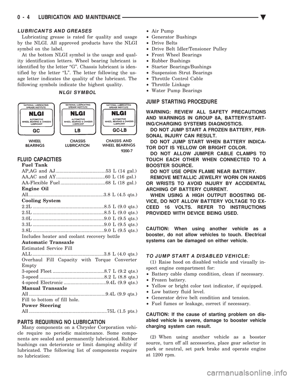
LUBRICANTS AND GREASES
Lubricating grease is rated for quality and usage
by the NLGI. All approved products have the NLGI
symbol on the label. At the bottom NLGI symbol is the usage and qual-
ity identification letters. Wheel bearing lubricant is
identified by the letter ``G''. Chassis lubricant is iden-
tified by the letter ``L''. The letter following the us-
age letter indicates the quality of the lubricant. The
following symbols indicate the highest quality.
FLUID CAPACITIES
Fuel Tank
AP,AG and AJ ......................................53 L (14 gal.)
AA,AC and AY .....................................60 L (16 gal.)
AA-Flexible Fuel ..................................68 L (18 gal.)
Engine Oil
All.........................................................3.8 L (4.5 qts.)
Cooling System
2.2L ......................................................8.5 L (9.0 qts.)
2.5L ......................................................8.5 L (9.0 qts.)
3.0L ......................................................9.0 L (9.5 qts.)
3.3L ......................................................9.0 L (9.5 qts.)
3.8L ......................................................9.0 L (9.5 qts.)
Includes heater and coolant recovery bottle
Automatic Transaxle
Estimated Service Fill
ALL ......................................................3.8 L (4.0 qts.)
Overhaul Fill Capacity with Torque Converter
Empty
3-speed Fleet .......................................8.7 L (9.2 qts.)
3-speed .................................................8.2 L (8.8 qts.)
4-speed Electronic ................................9.4L (9.9 qts.)
Manual Transaxle
All ..........................................................9.4L (9.9 qts.)
Fill to bottom of fill hole.
Power Steering
All ...........................................................75L (1.5 pts.)
PARTS REQUIRING NO LUBRICATION
Many components on a Chrysler Corporation vehi-
cle require no periodic maintenance. Some compo-
nents are sealed and permanently lubricated. Rubber
bushings can deteriorate or limit damping ability if
lubricated. The following list of components require
no lubrication: ²
Air Pump
² Generator Bushings
² Drive Belts
² Drive Belt Idler/Tensioner Pulley
² Front Wheel Bearings
² Rubber Bushings
² Starter Bearings/Bushings
² Suspension Strut Bearings
² Throttle Control Cable
² Throttle Linkage
² Water Pump Bearings
JUMP STARTING PROCEDURE
WARNING: REVIEW ALL SAFETY PRECAUTIONS
AND WARNINGS IN GROUP 8A, BATTERY/START-
ING/CHARGING SYSTEMS DIAGNOSTICS. DO NOT JUMP START A FROZEN BATTERY, PER-
SONAL INJURY CAN RESULT. DO NOT JUMP START WHEN BATTERY INDICA-
TOR DOT IS YELLOW OR BRIGHT COLOR. DO NOT ALLOW JUMPER CABLE CLAMPS TO
TOUCH EACH OTHER WHEN CONNECTED TO A
BOOSTER SOURCE. DO NOT USE OPEN FLAME NEAR BATTERY.
REMOVE METALLIC JEWELRY WORN ON HANDS
OR WRISTS TO AVOID INJURY BY ACCIDENTAL
ARCHING OF BATTERY CURRENT. WHEN USING A HIGH OUTPUT BOOSTING DE-
VICE, DO NOT ALLOW BATTERY VOLTAGE TO EX-
CEED 16 VOLTS. REFER TO INSTRUCTIONS
PROVIDED WITH DEVICE BEING USED.
CAUTION: When using another vehicle as a
booster, do not allow vehicles to touch. Electrical
systems can be damaged on either vehicle.
TO JUMP START A DISABLED VEHICLE:
(1) Raise hood on disabled vehicle and visually in-
spect engine compartment for:
² Battery cable clamp condition, clean if necessary.
² Frozen battery.
² Yellow or bright color test indicator, if equipped.
² Low battery fluid level.
² Generator drive belt condition and tension.
² Fuel fumes or leakage, correct if necessary.
CAUTION: If the cause of starting problem on dis-
abled vehicle is severe, damage to booster vehicle
charging system can result.
(2) When using another vehicle as a booster
source, turn off all accessories, place gear selector in
park or neutral, set park brake and operate engine
at 1200 rpm.
NLGI SYMBOL
0 - 4 LUBRICATION AND MAINTENANCE Ä
Page 220 of 2438

(7) Unfasten brackets on steel heater water line at
dash panel and left frame rail. On Manual Transmis-
sion vehicles, unfasten clutch cable bracket at shock
tower and move aside. (8) Slide the power brake unit up and to the left
(mounting holes are slotted) on the dash panel, then
tilt inboard and up to remove.
CAUTION: Do not attempt to disassemble power
brake unit as this booster is serviced ONLY as a
complete assembly.
INSTALL (1) Position power brake booster onto dash panel.
(2) Install and tighten the 4 power brake booster to
dash panel mounting nuts (Fig. 5) to 29 N Im (250 in.
lbs.) torque. (3) Install steel heater water line and clutch cable
bracket, if so equipped. (4) Carefully position master cylinder on power
brake unit. (5) Install and tighten the 2 master cylinder to
power booster mounting nuts (Fig. 4) to 29 N Im (250
in. lbs.) torque. (6) Connect vacuum hose onto the check valve, lo-
cated on the power brake unit. (7) Using lubriplate, or equivalent, coat the bearing
surface of pedal pin (Fig. 5). (8) Connect power brake booster input rod to brake
pedal pin and install a NEW retainer clip. Use only a
new retainer clip DO NOT USE the old clip. (9) Check stop light operation.
WHEEL BEARINGS
FRONT WHEEL BEARINGS
Front wheel drive vehicles are equipped with per-
manently sealed front wheel bearings. There is no
periodic lubrication or maintenance recommended for
these units. However if during servicing of the brake
system, service to the front wheel bearing is required
refer to Group 2, Suspension in this service manual.
REAR WHEEL BEARINGS
NORMAL SERVICE
The lubricant in the rear wheel bearings should be
inspected whenever the hubs are removed to inspect
or service the brake system. Or at least every 30,000
miles (48,000 km). The bearings should be cleaned
and repacked with a High Temperature Multipurpose
E.P. Grease whenever the disc brake rotors are re-
surfaced.
INSPECTION
Check lubricant to see that it is adequate in quan-
tity and quality. If the grease is low in quantity, con-
tains dirt, appears dry or has been contaminated
with water, it will appear milky. The bearings then must be cleaned and repacked.
Do not add grease to
a wheel bearing that already has grease packed
in it. Relubricate completely. Mixing of different
types of greases in wheel bearings should be
avoided since it may result in excessive thinning
and leakage of the grease.
REMOVAL AND INSTALLATION
For the servicing, removal and installation of the
rear wheel bearings follow the procedure listed below. (1) Remove the rear tire and wheel assembly.
(2) On rear disc brake equipped vehicles remove the
caliper and rotor. Support the caliper out of the way.
Do not allow the caliper to hang by the hydraulic
hose. See disc brake section in this group for caliper
removal procedure. (3) Remove grease cap, cotter pin, nut lock, nut,
thrust washer and outer wheel bearing. (4) Carefully slide hub or drum from spindle. Do not
drag inner bearing or grease seal over stub axle
(thread, bearing, and oil seal may be damaged.) Using
an appropriate tool remove the grease seal and inner
bearing from the drum or hub. Discard grease
Fig. 5 Power Brake Booster Mounting
5 - 70 BRAKES Ä
Page 343 of 2438
COOLING SYSTEM
CONTENTS
page page
ACCESSORY DRIVE BELTS ............... 24
ENGINE BLOCK HEATER ................. 28
GENERAL INFORMATION .................. 1 SERVICE PROCEDURES
.................. 10
SPECIFICATIONS ....................... 29
GENERAL INFORMATION
Throughout this group, references may be made to
a particular vehicle by letter or number designation.
A chart showing the breakdown of these designations
is included in the Introduction Section at the front of
this service manual.
COOLING SYSTEM
The cooling system consists of an engine cooling
module, thermostat, coolant, a water pump to circu-
late the coolant. The engine cooling module may con-
sist of a radiator, electric fan motor, shroud, radiator
pressure cap, coolant reserve system, transmission oil
cooler, hoses, clamps, air condition condenser, trans-
mission oil lines and charge air cooler.
² When Engine is cold: Thermostat is closed, cooling
system has no flow through the radiator. The coolant
bypass flows through the engine only. ²
When Engine is warm: Thermostat is open, cooling
system has bypass flow and coolant flow through ra-
diator. Its primary purpose is to maintain engine temper-
ature in a range that will provide satisfactory engine
performance and emission levels under all expected
driving conditions. It also provides hot water (cool-
ant) for heater performance and cooling for auto-
matic transmission oil. It does this by transferring
heat from engine metal to coolant, moving this
heated coolant to the radiator, and then transferring
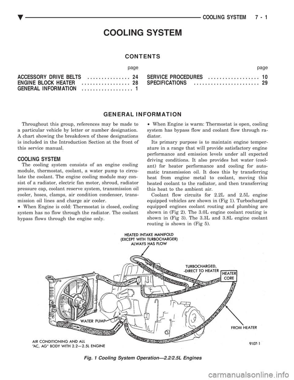
this heat to the ambient air. Coolant flow circuits for 2.2L and 2.5L engine
equipped vehicles are shown in (Fig 1). Turbocharged
equipped engines coolant routing and plumbing are
shown in (Fig 2). The 3.0L engine coolant routing is
shown in (Fig 3). The 3.3L and 3.8L engine coolant
routing is shown in (Fig 5).
Fig. 1 Cooling System OperationÐ2.2/2.5L Engines
Ä COOLING SYSTEM 7 - 1
Page 344 of 2438

TURBOCHARGER COOLANT ROUTING
Engines equipped with a Turbocharger maintain a
continuous engine coolant flow through the Turbo-
charger bearing housing water jacket. Hose and tube
assemblies provide a closed loop coolant flow from
the cylinder block water jacket to the turbocharger
housing and back to the cylinder head waterbox (Fig.
2). Excluding heated intake manifold hose routing
(hose is routed from waterbox directly to heater), all
other system functions are essentially the same as
shown for standard engines. During any reassembly procedures all pipe fittings
in water jacket, bearing housing and waterbox re-
quire cleaning and application of thread sealant for
entire length of threads. Tighten all fittings to
torque specified in (Fig 2).
WATER PIPESÐ3.0L
The 3.0L engines use metal piping beyond the
lower radiator hose to route coolant to the suction
side of water pump, located in the V of the cylinder
banks. These pipes are also provided with inlet nipples for
thermostat bypass and heater return coolant hos-
es,and brackets for rigid engine attachment. The
pipes employ O-rings for sealing at their interconnec-
tion and to the water pump (Fig. 4).
Fig. 2 Turbocharger-Tube Hose AssembliesÐTurbo III Engine
Fig. 3 Cooling System OperationÐ3.0L Engine
7 - 2 COOLING SYSTEM Ä
Page 352 of 2438
SERVICE PROCEDURES INDEX
page page
Automatic Transmission Oil Coolers .......... 23
Coolant ................................ 14
Coolant Recovery System (CRS) ............. 17
Cooling System Drain, Clean, Flush and Refill . . 15
Electric Fan Motor ........................ 22
Engine Thermostats ....................... 13
Fan Shroud ............................. 23 Fans
.................................. 21
Radiator Hoses .......................... 21
Radiator Pressure Cap .................... 18
Radiators ............................... 18
Testing System for Leaks .................. 17
Water Pumps ........................... 10
WATER PUMPS
A quick test to tell whether or not the pump is
working is to see if the heater warms properly. A
defective pump will not be able to circulate heated
coolant through the long heater hose. The water pump on all models can be replaced
without discharging the air conditioning system.
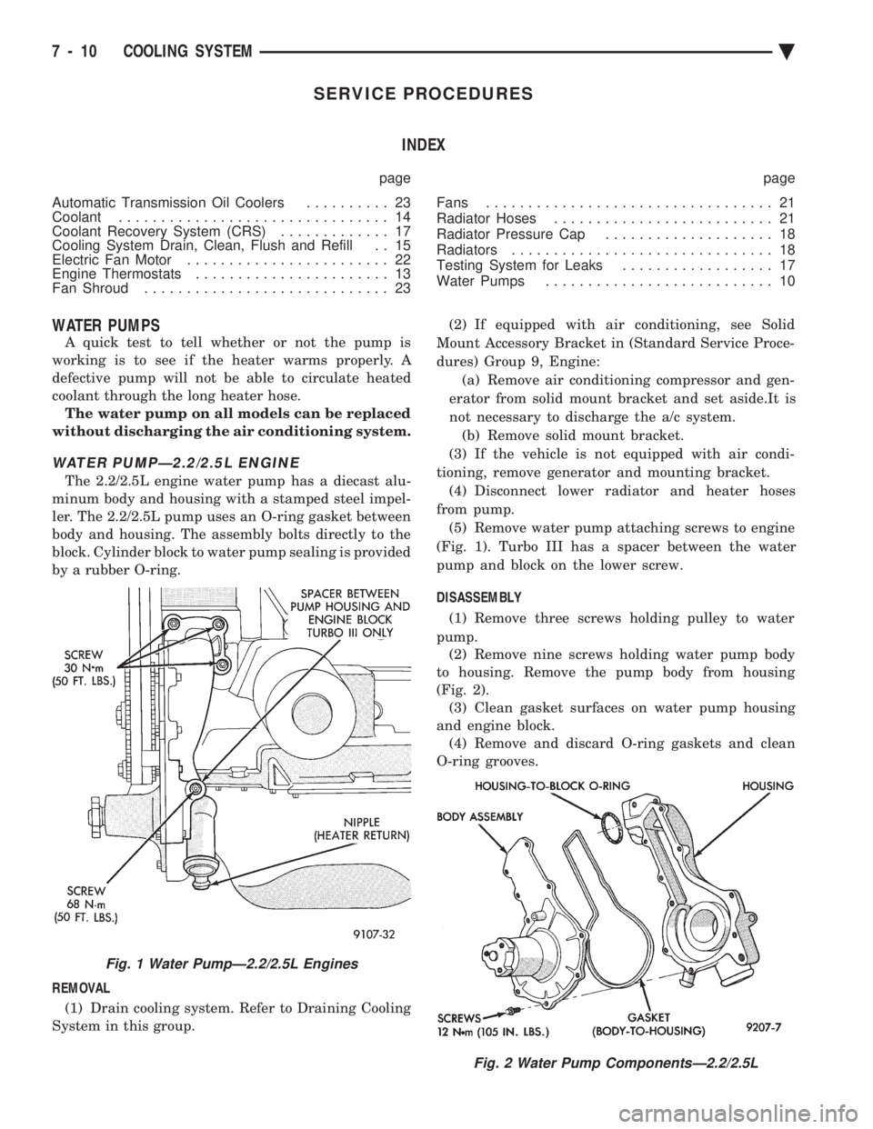
WATER PUMPÐ2.2/2.5L ENGINE
The 2.2/2.5L engine water pump has a diecast alu-
minum body and housing with a stamped steel impel-
ler. The 2.2/2.5L pump uses an O-ring gasket between
body and housing. The assembly bolts directly to the
block. Cylinder block to water pump sealing is provided
by a rubber O-ring.
REMOVAL (1) Drain cooling system. Refer to Draining Cooling
System in this group. (2) If equipped with air conditioning, see Solid
Mount Accessory Bracket in (Standard Service Proce-
dures) Group 9, Engine: (a) Remove air conditioning compressor and gen-
erator from solid mount bracket and set aside.It is
not necessary to discharge the a/c system. (b) Remove solid mount bracket.
(3) If the vehicle is not equipped with air condi-
tioning, remove generator and mounting bracket. (4) Disconnect lower radiator and heater hoses
from pump. (5) Remove water pump attaching screws to engine
(Fig. 1). Turbo III has a spacer between the water
pump and block on the lower screw.
DISASSEMBLY (1) Remove three screws holding pulley to water
pump. (2) Remove nine screws holding water pump body
to housing. Remove the pump body from housing
(Fig. 2). (3) Clean gasket surfaces on water pump housing
and engine block. (4) Remove and discard O-ring gaskets and clean
O-ring grooves.
Fig. 2 Water Pump ComponentsÐ2.2/2.5L
Fig. 1 Water PumpÐ2.2/2.5L Engines
7 - 10 COOLING SYSTEM Ä
Page 353 of 2438
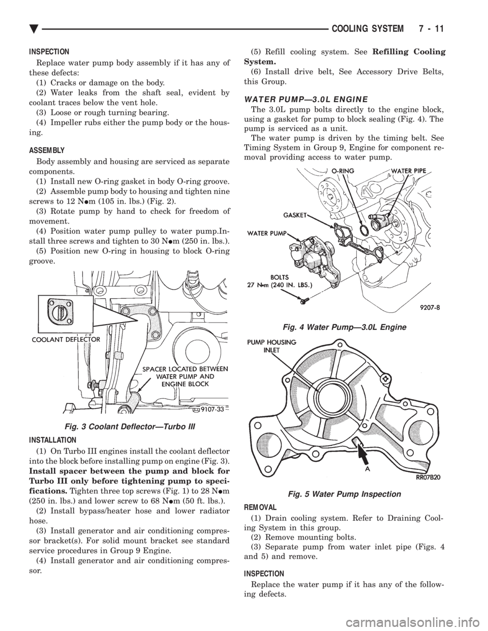
INSPECTION Replace water pump body assembly if it has any of
these defects: (1) Cracks or damage on the body.
(2) Water leaks from the shaft seal, evident by
coolant traces below the vent hole. (3) Loose or rough turning bearing.
(4) Impeller rubs either the pump body or the hous-
ing.
ASSEMBLY
Body assembly and housing are serviced as separate
components. (1) Install new O-ring gasket in body O-ring groove.
(2) Assemble pump body to housing and tighten nine
screws to 12 N Im (105 in. lbs.) (Fig. 2).
(3) Rotate pump by hand to check for freedom of
movement. (4) Position water pump pulley to water pump.In-
stall three screws and tighten to 30 N Im (250 in. lbs.).
(5) Position new O-ring in housing to block O-ring
groove.
INSTALLATION (1) On Turbo III engines install the coolant deflector
into the block before installing pump on engine (Fig. 3).
Install spacer between the pump and block for
Turbo III only before tightening pump to speci-
fications. Tighten three top screws (Fig. 1) to 28 N Im
(250 in. lbs.) and lower screw to 68 N Im (50 ft. lbs.).
(2) Install bypass/heater hose and lower radiator
hose. (3) Install generator and air conditioning compres-
sor bracket(s). For solid mount bracket see standard
service procedures in Group 9 Engine. (4) Install generator and air conditioning compres-
sor. (5) Refill cooling system. See
Refilling Cooling
System. (6) Install drive belt, See Accessory Drive Belts,
this Group.
WATER PUMPÐ3.0L ENGINE
The 3.0L pump bolts directly to the engine block,
using a gasket for pump to block sealing (Fig. 4). The
pump is serviced as a unit. The water pump is driven by the timing belt. See
Timing System in Group 9, Engine for component re-
moval providing access to water pump.
REMOVAL (1) Drain cooling system. Refer to Draining Cool-
ing System in this group. (2) Remove mounting bolts.
(3) Separate pump from water inlet pipe (Figs. 4
and 5) and remove.
INSPECTION Replace the water pump if it has any of the follow-
ing defects.
Fig. 4 Water PumpÐ3.0L Engine
Fig. 5 Water Pump Inspection
Fig. 3 Coolant DeflectorÐTurbo III
Ä COOLING SYSTEM 7 - 11
Page 355 of 2438

(5) Install drive belt. See Accessory Drive Belts
this group. (6) Install right front lower fender shield.
(7) Refill Cooling System. See Refilling Cooling
System in this section.
ENGINE THERMOSTATS
The 2.2 and 2.5L engine thermostats are located on
the front of the engine (radiator side) in the water
box which is part of the cylinder head construction
(Fig. 9). Turbo III thermostat is located in the water
box located on the driver side of the cylinder head
(Fig. 10). These thermostats do not have an air bleed notch.
The 3.0L engine thermostat is located in a water
box, formed in the timing belt end of the intake man-
ifold. This thermostat has an air bleed valve, located
in the thermostat flange (Fig. 11). The 3.3/3.8L engine thermostat is located in a wa-
ter box, formed in the drive belt side of the intake
manifold (Fig. 13).
DESCRIPTION AND OPERATION
The engine cooling thermostats are wax pellet
driven, reverse poppet choke type. They are designed
to provide the fastest warm up possible by prevent-
ing leakage through them and to guarantee a mini-
mum engine operating temperature of 88 to 93ÉC
(192 to 199ÉF). They also automatically reach wide
open so they do not restrict flow to the radiator as
temperature of the coolant rises in hot weather to
around 104ÉC (220ÉF). Above this temperature the
coolant temperature is controlled by the radiator,
fan, and ambient temperature, not the thermostat.
OPERATION AND TESTING
The thermostat is operated by a wax filled con-
tainer (pellet) which is sealed so that when heated to
a predetermined temperature. The wax expands
enough to overcome the closing spring and water
pump pressure, which forces the valve to open. Cool-
ant leakage into the pellet will cause a thermostat to
fail open. Do not attempt to free up a thermostat
with a screwdriver. The open too soon type failure mode is included in
the onboard diagnosis. The check engine light will
not be lit by an open too soon condition. If it has
failed open, code 17 will be set. Do not change a ther-
mostat for lack of heat by gauge or heater perfor-
mance, unless code 17 is present, see diagnosis for
other probable causes. Failing shut is the normal
long term mode of failure, and normally, only on
high mileage vehicles. The temperature gauge will
indicate this, Refer to diagnosis in this section.
REMOVAL
(1) Drain cooling system down to thermostat level
or below. (2) Remove thermostat housing bolts and housing
(Figs. 9, 10, 11 and 13). (3) Remove thermostat, discard gasket and clean
both gasket sealing surfaces.
INSTALLATIONÐ2.2/2.5L AND TURBO III ENGINES
Place a new gasket (dipped in clean water) on wa-
ter box surface, center thermostat in water box on
gasket. Place housing over gasket and thermostat,
making sure thermostat is in the thermostat hous-
ing. Bolt housing to water box (Figs. 9 and 10).
Tighten bolts to 28 N Im (250 in. lbs.). Refill cooling
system (see Refilling System ).
INSTALLATIONÐ3.0L ENGINE
Center thermostat in water box pocket. Check that
the flange is seated correctly in the countersunk por-
tion of the intake manifold water box (Figs. 11 and
12). Install new gasket on water box. Install housing
over gasket and thermostat and tighten bolts to 12
N Im (133 in. lbs. torque).
Fig. 9 Thermostat, Housing, and Water BoxÐ2.2/
2.5L Engine
Fig. 10 Thermostat, Housing, and Water BoxÐTurbo III
Ä COOLING SYSTEM 7 - 13