1993 CHEVROLET PLYMOUTH ACCLAIM air filter
[x] Cancel search: air filterPage 44 of 2438
ENGINE INDEX
page page
Engine Oil Filter .......................... 9
Battery ................................ 15
Crankcase Ventilation System ............... 13
Drive Belts ............................. 14
Emission Control System ................... 14
Engine Air Cleaner ....................... 11
Engine Cooling System .................... 10 Engine Oil
............................... 8
Frequency of Engine Oil and Filter Changes ..... 8
Fuel Filter .............................. 14
Fuel Recommendations .................... 14
Ignition Cables, Distributor Cap, and Rotor ..... 14
Rubber and Plastic Component Inspection ...... 15
Spark Plugs ............................ 14
FREQUENCY OF ENGINE OIL AND FILTER
CHANGES
ENGINE OIL
Road conditions as well as your kind of driving af-
fect the interval at which your oil should be changed.
Check the following to determine if any apply to you:
² Frequent short trip driving less than 8 kilometers
(5 miles)
² Frequent driving in dusty conditions
² Frequent trailer towing
² Extensive idling (such as vehicle operation in stop
and go traffic)
² More than 50% of your driving is at sustained
high speeds during hot weather, above 32ÉC (90ÉF) If any of these apply to you then change your en-
gine oil every 4 800 kilometers (3,000 miles) or 3
months, whichever comes first. If none of these apply to you then change your oil
every 12 000 kilometers (7,500 miles) or 6 months,
whichever comes first. If none of these apply and the vehicle is in com-
mercial type service such as, Police, Taxi or Limou-
sine and principally used for highway driving of 40
kilometers (25 miles) or more between stations, the
engine oil should be changed every 8 000 kilometers
(5,000 miles) or 6 months, whichever comes first.
FLEXIBLE FUEL VEHICLES
Flexible fuel is corrosive and contributes to engine
oil contamination. When flexible fuel is being used,
the engine oil should be changed every 8 000 kilome-
ters (5,000 miles) or 6 months, whichever comes first.
OIL FILTER
The engine oil filter should be replaced with a new
filter at every second oil change.
ENGINE OIL
WARNING: NEW OR USED ENGINE OIL CAN BE IR-
RITATING TO THE SKIN. AVOID PROLONGED OR
REPEATED SKIN CONTACT WITH ENGINE OIL.
CONTAMINANTS IN USED ENGINE OIL, CAUSED
BY INTERNAL COMBUSTION, CAN BE HAZARDOUS TO YOUR HEALTH. THOROUGHLY WASH EX-
POSED SKIN WITH SOAP AND WATER. DO NOT WASH SKIN WITH GASOLINE, DIESEL
FUEL, THINNER, OR SOLVENTS, HEALTH PROB-
LEMS CAN RESULT. DO NOT POLLUTE, DISPOSE OF USED ENGINE
OIL PROPERLY. CONTACT YOUR DEALER OR
GOVERNMENT AGENCY FOR LOCATION OF COL-
LECTION CENTER IN YOUR AREA.
BREAK-IN PERIOD
CAUTION: Wide open throttle operation in low
gears, before engine break-in period is complete,
can damage engine.
On a Chrysler Corporation vehicle an extended
break-in period is not required. Driving speeds of not
over 80-90 km/h (50-55 mph) for the first 100 km (60
miles) is recommended. Hard acceleration and high
engine rpm in lower gears should be avoided.
SELECTING ENGINE OIL
CAUTION: Do not use non-detergent or straight
mineral oil when adding or changing crankcase lu-
bricant. Engine or Turbocharger failure can result.
The factory fill engine oil is a high quality, energy
conserving, crankcase lubricant. The Recommended
SAE Viscosity Grades chart defines the viscosity
grades that must be used based on temperature in
the region where vehicle is operated and optional
equipment.
NON-FLEXIBLE FUEL VEHICLES Chrysler Corporation recommends that Mopar mo-
tor oil, or equivalent, be used when adding or chang-
ing crankcase lubricant. The API symbol (Fig. 1) on
the container indicates the viscosity grade, quality
and fuel economy ratings of the lubricant it contains.
Use ENERGY CONSERVING II motor oil with API
SERVICE SG or SG/CD classification.
0 - 8 LUBRICATION AND MAINTENANCE Ä
Page 46 of 2438
ENGINE COOLING SYSTEM
WARNINGS AND PRECAUTIONS
WARNING: ANTIFREEZE IS AN ETHYLENE GLYCOL
BASE COOLANT AND IS HARMFUL IF SWAL-
LOWED OR INHALED. IF SWALLOWED, DRINK
TWO GLASSES OF WATER AND INDUCE VOMIT-
ING. IF INHALED, MOVE TO FRESH AIR AREA.
SEEK MEDICAL ATTENTION IMMEDIATELY. DO
NOT STORE IN OPEN OR UNMARKED CONTAIN-
ERS. WASH SKIN AND CLOTHING THOROUGHLY
AFTER COMING IN CONTACT WITH ETHYLENE
GLYCOL. KEEP OUT OF REACH OF CHILDREN. DISPOSE OF GLYCOL BASE COOLANT PROP-
ERLY, CONTACT YOUR DEALER OR GOVERNMENT
AGENCY FOR LOCATION OF COLLECTION CEN-
TER IN YOUR AREA. DO NOT OPEN A COOLING SYSTEM WHEN THE
ENGINE IS AT RUNNING TEMPERATURE, PER-
SONAL INJURY CAN RESULT. AVOID RADIATOR COOLING FAN WHEN ENGINE
COMPARTMENT RELATED SERVICE IS PER-
FORMED, PERSONAL INJURY CAN RESULT.
CAUTION: Do not use straight antifreeze as engine
coolant, inadequate engine running temperatures
can result. Do not operate vehicle without proper concentra-
tion of recommended ethylene glycol coolant, high
running temperatures and cooling system corrosion
can result.
The engine cooling system will develop internal
pressure of 97 to 123 kPa (14 to 18 psi) at normal op-
erating temperature. Allow the vehicle approxi-
mately one half hour to cool off before opening the
cooling system. As an indicator of pressure, squeeze
the upper radiator hose between index finger and
thumb. If it collapses with little effort the system
would have low internal pressure and should be safe
to open to the first safety notch of the radiator cap.
Refer to Group 7, Cooling System.
COOLING SYSTEM INSPECTION
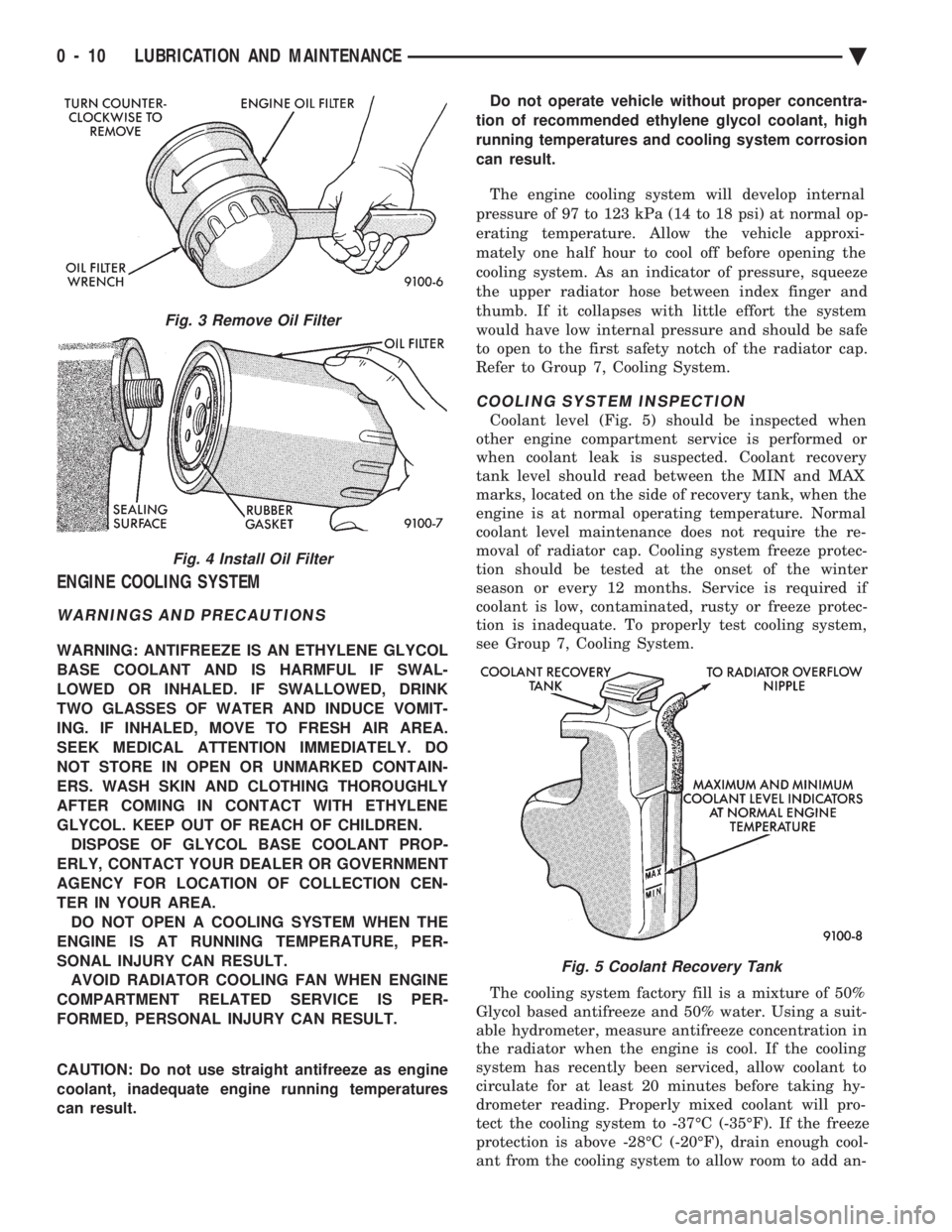
Coolant level (Fig. 5) should be inspected when
other engine compartment service is performed or
when coolant leak is suspected. Coolant recovery
tank level should read between the MIN and MAX
marks, located on the side of recovery tank, when the
engine is at normal operating temperature. Normal
coolant level maintenance does not require the re-
moval of radiator cap. Cooling system freeze protec-
tion should be tested at the onset of the winter
season or every 12 months. Service is required if
coolant is low, contaminated, rusty or freeze protec-
tion is inadequate. To properly test cooling system,
see Group 7, Cooling System.
The cooling system factory fill is a mixture of 50%
Glycol based antifreeze and 50% water. Using a suit-
able hydrometer, measure antifreeze concentration in
the radiator when the engine is cool. If the cooling
system has recently been serviced, allow coolant to
circulate for at least 20 minutes before taking hy-
drometer reading. Properly mixed coolant will pro-
tect the cooling system to -37ÉC (-35ÉF). If the freeze
protection is above -28ÉC (-20ÉF), drain enough cool-
ant from the cooling system to allow room to add an-
Fig. 3 Remove Oil Filter
Fig. 4 Install Oil Filter
Fig. 5 Coolant Recovery Tank
0 - 10 LUBRICATION AND MAINTENANCE Ä
Page 47 of 2438
tifreeze to achieve adequate protection. A mix table
on the coolant container indicates the amount of an-
tifreeze required to winterize the cooling system
based on the capacity, see Capacity Chart in General
Information section of this group.
SELECTING ANTIFREEZE
Chrysler Corporation recommends Mopar Anti-
freeze/Summer Coolant, or equivalent be used to win-
terize and protect cooling system.
RADIATOR CAP
The radiator cap must be secure to provide proper
pressure release and coolant recovery. Inspect and
test radiator cap when cooling system service is per-
formed or when problem is suspected.
COOLING SYSTEM SERVICE
The cooling system should be drained, flushed and
filled with the proper coolant mixture at the inter-
vals described in the Lubrication and Maintenance
Schedules. Refer to General Information section of
this group. For proper service instructions see Group
7, Cooling System.
ENGINE AIR CLEANER
The engine air cleaner should be serviced at the in-
tervals described in the Lubrication and Mainte-
nance Schedules. Refer to General Information
section of this group. Additional information can be
found in Group 14, Fuel System and Group 25, Emis-
sion System. Inspect all air cleaner hoses or tubes for
damage or leaks when other engine compartment
service is performed. Replace faulty components.
AIR CLEANER SERVICE
CAUTION: The air cleaner cover must be installed
properly for the emissions system and engine con-
troller to function correctly. Do not immerse paper air filter element or temper-
ature sensor in cleaning solvents, damage can re-
sult.
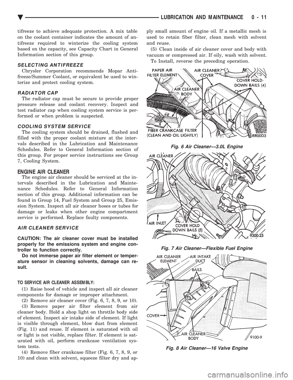
TO SERVICE AIR CLEANER ASSEMBLY: (1) Raise hood of vehicle and inspect all air cleaner
components for damage or improper attachment. (2) Remove air cleaner cover (Fig. 6, 7, 8, 9, or 10).
(3) Remove paper air filter element from air
cleaner body. Hold a shop light on throttle body side
of element. Inspect air intake side of element. If light
is visible through element, blow dust from element
(Fig. 11) and reuse. If element is saturated with oil
or light is not visible, replace filter. If element is sat-
urated with oil, perform crankcase ventilation sys-
tem tests. (4) Remove fiber crankcase filter (Fig. 6, 7, 8, 9, or
10) and clean with solvent, squeeze filter dry and ap- ply small amount of engine oil. If a metallic mesh is
used to retain fiber filter, clean mesh with solvent
and reuse.
(5) Clean inside of air cleaner cover and body with
vacuum or compressed air. If oily, wash with solvent. To Install, reverse the preceding operation.
Fig. 6 Air CleanerÐ3.0L Engine
Fig. 7 Air CleanerÐFlexible Fuel Engine
Fig. 8 Air CleanerÐ16 Valve Engine
Ä LUBRICATION AND MAINTENANCE 0 - 11
Page 49 of 2438
CRANKCASE VENTILATION SYSTEM
Engine crankcase pressure and emissions are
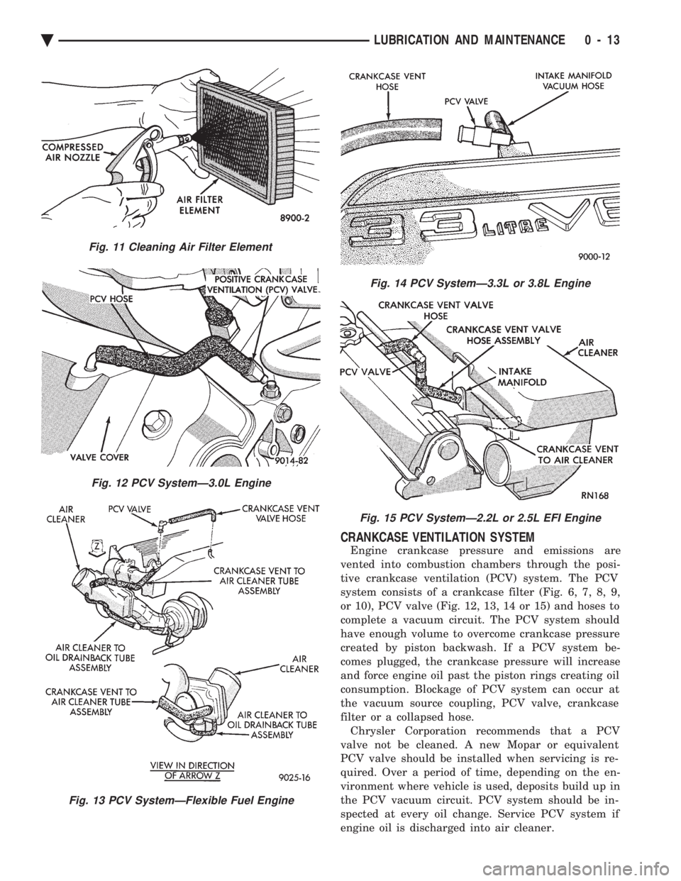
vented into combustion chambers through the posi-
tive crankcase ventilation (PCV) system. The PCV
system consists of a crankcase filter (Fig. 6, 7, 8, 9,
or 10), PCV valve (Fig. 12, 13, 14 or 15) and hoses to
complete a vacuum circuit. The PCV system should
have enough volume to overcome crankcase pressure
created by piston backwash. If a PCV system be-
comes plugged, the crankcase pressure will increase
and force engine oil past the piston rings creating oil
consumption. Blockage of PCV system can occur at
the vacuum source coupling, PCV valve, crankcase
filter or a collapsed hose. Chrysler Corporation recommends that a PCV
valve not be cleaned. A new Mopar or equivalent
PCV valve should be installed when servicing is re-
quired. Over a period of time, depending on the en-
vironment where vehicle is used, deposits build up in
the PCV vacuum circuit. PCV system should be in-
spected at every oil change. Service PCV system if
engine oil is discharged into air cleaner.
Fig. 11 Cleaning Air Filter Element
Fig. 12 PCV SystemÐ3.0L Engine
Fig. 13 PCV SystemÐFlexible Fuel Engine
Fig. 14 PCV SystemÐ3.3L or 3.8L Engine
Fig. 15 PCV SystemÐ2.2L or 2.5L EFI Engine
Ä LUBRICATION AND MAINTENANCE 0 - 13
Page 50 of 2438
PCV SYSTEM TEST
Refer to group 25, Emission Control System for
proper procedures to test PCV system.
FUEL RECOMMENDATIONS
Chrysler Corporation recommends that only fuel pur-
chased from a reputable retailer be used. Use high qual-
ity, unleaded gasoline to provide satisfactory
driveability and highest fuel economy. Gasoline contain-
ing detergent and corrosion control additives are desire-
able. If the engine develops spark knock (audible ping),
poor performance, hard starting or stalling, purchase
fuel from another source. Engine performance can vary
when using different brands of gasoline with the same
octane rating. Occasional light engine spark knock un-
der heavy acceleration, at low speed or when vehicle is
heavily loaded is not harmful. Extended periods of
spark knock under moderate acceleration or at cruising
speed can damage the engine. The cause of excessive
spark knock condition must be diagnosed and corrected.
For diagnostic procedures refer to Group 14, Fuel Sys-
tem and Powertrain Diagnostic Procedures manual.
SELECTING GASOLINE
CAUTION:Do not use fuel containing METHANOL
(methyl or wood alcohol), damage to fuel system
will result. Do not use leaded gasoline, damage to catalytic
converter will result and vehicle will not conform to
emission control standards.
ETHANOL, MTBE OR ETBE BLENDS
All Chrysler Corporation vehicles are designed to
use unleaded gasoline ONLY. Gasohol blends, con-
taining 10% Ethanol (ethyl or grain alcohol) 90% un-
leaded gasoline can be used provided it has adequate
octane rating. Fuel blends containing up to 15% MTBE (Methyl
Tertiary Butyl Ether) and 85% unleaded gasoline can
be used. Fuel blends containing up to 17% ETBE
(Ethyl Tertiary Butyl Ether) and 83% unleaded gas-
oline can also be used. Fuel blended with ethanol, MTBE or ETBE are
also referred to as reformulated or clean air gasoline.
These fuels contribute less emissions to the atmo-
sphere. Chrysler Corporation recommends that
blended fuels be used when available
METHANOL BLENDS Using gasoline blended with methanol can result
in starting and driveability problems. Deterioration
of fuel system components will result. Methanol in-
duced problems are not the responsibility of Chrysler
Corporation and may not be covered by the vehicle
warranty. NON-TURBOCHARGED ENGINES
Use regular unleaded gasoline having a minimum
octane rating of 87 (R+M)/2. Higher octane premium
unleaded gasoline can be used if desired.
2.2L 16 VALVE TURBOCHARGED ENGINE
Use premium unleaded gasoline having a mini-
mum octane rating of 91 (R+M)/2. Gasoline with oc-
tane rating less than 91 (R+M)/2 can be used if
recommended gasoline is not available. Low octane
gasoline will reduce engine performance.
FLEXIBLE FUEL VEHICLES
CAUTION: Do not use 100% methanol, damage to
fuel system can result. Use unleaded regular gasoline having a minimum
octane rating of 87 (R=M)/2 and M85 fuel that is
85% methanol and 15% unleaded gasoline, or a mix-
ture of these two.
FUEL FILTER
The fuel filter requires service only when a fuel
contamination problem is suspected. For proper diag-
nostic and service procedures refer to Group 14, Fuel
System,
IGNITION CABLES, DISTRIBUTOR CAP, AND
ROTOR
Inspect and test ignition cables, distributor cap and
rotor when the spark plugs are replaced. Oil and
grime should be cleaned from the ignition cables and
distributor cap to avoid possible spark plug fouling.
Mopar, Foamy Engine Degreaser, or equivalent is
recommended for cleaning the engine compartment.
For proper service and diagnostic procedures refer to
Group 8D, Ignition System.
SPARK PLUGS
Ignition spark plugs should be replaced at the
mileage interval described in the Lubrication and
Maintenance Schedules. Refer to the General Infor-
mation section of this group. For proper service pro-
cedures refer to Group 8D, Ignition Systems.
DRIVE BELTS
Inspect and adjust drive belts at the interval de-
scribed in the Lubrication and Maintenance Sched-
ules. Refer to General Information section of this
group. For proper inspection and adjustment proce-
dures, see Group 7, Cooling System.
EMISSION CONTROL SYSTEM
Inspect all emission control components and hoses
when other under hood service is performed. Refer to
emission system Vacuum Hose Label located on the
0 - 14 LUBRICATION AND MAINTENANCE Ä
Page 53 of 2438
should be above ADD mark. Add fluid only if level is
below ADD mark on dipstick when transaxle is
warm.The automatic transaxle does not require periodic
maintenance when used for general transportation. If
the vehicle is subjected to severe service conditions,
the automatic transaxle will require fluid/filter
change and band adjustments every 24 000 km
(15,000 miles). For additional information, refer to
Severe Service paragraph and Lubrication and Main-
tenance Schedules in General Information section of
this group. The fluid and filter should be changed
when water contamination is suspected. If fluid has
foamy or milky appearance, it is probably contami-
nated. If the fluid appears brown or dark and a foul
odor is apparent, the fluid is burned, transaxle re-
quires maintenance or service. A circular magnet lo-
cated in the transaxle pan, collects metallic particles
circulating in the oil. For proper diagnostic and ser-
vice procedures, refer to Group 21, Automatic Tran-
saxle.
SELECTING AUTOMATIC TRANSAXLE FLUID
Chrysler Corporation recommends Mopar ATF Plus
(automatic transmission fluid type 7176) be used to
add to or replace automatic transaxle fluid. If ATF
Plus is not available use Mopar Dexron II tAuto-
matic Transmission Fluid or equivalent.
DRIVE SHAFT CV AND TRIPOD JOINT BOOTS
The front drive shaft constant velocity and tripod
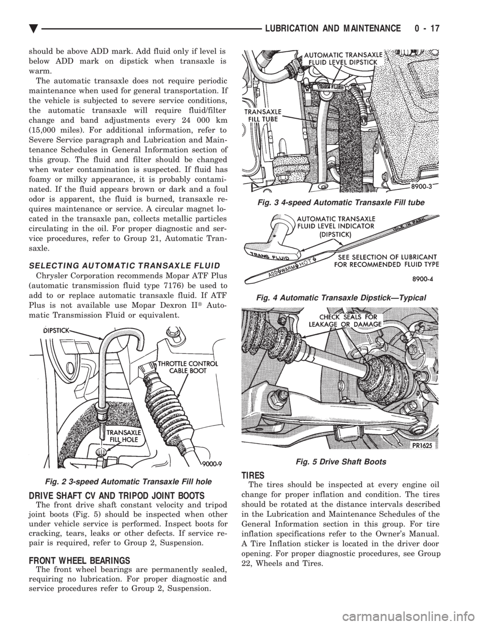
joint boots (Fig. 5) should be inspected when other
under vehicle service is performed. Inspect boots for
cracking, tears, leaks or other defects. If service re-
pair is required, refer to Group 2, Suspension.
FRONT WHEEL BEARINGS
The front wheel bearings are permanently sealed,
requiring no lubrication. For proper diagnostic and
service procedures refer to Group 2, Suspension.
TIRES
The tires should be inspected at every engine oil
change for proper inflation and condition. The tires
should be rotated at the distance intervals described
in the Lubrication and Maintenance Schedules of the
General Information section in this group. For tire
inflation specifications refer to the Owner's Manual.
A Tire Inflation sticker is located in the driver door
opening. For proper diagnostic procedures, see Group
22, Wheels and Tires.Fig. 2 3-speed Automatic Transaxle Fill hole
Fig. 3 4-speed Automatic Transaxle Fill tube
Fig. 4 Automatic Transaxle DipstickÐTypical
Fig. 5 Drive Shaft Boots
Ä LUBRICATION AND MAINTENANCE 0 - 17
Page 229 of 2438
PUMP/MOTOR ASSEMBLY
NOTE: The (CAB) does not control the opera-
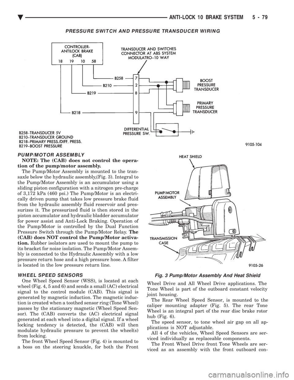
tion of the pump/motor assembly. The Pump/Motor Assembly is mounted to the tran-
saxle below the hydraulic assembly,(Fig. 3). Integral to
the Pump/Motor Assembly is an accumulator using a
sliding piston configuration with a nitrogen pre-charge
of 3,172 kPa (460 psi.) The Pump/Motor is an electri-
cally driven pump that takes low pressure brake fluid
from the hydraulic assembly fluid reservoir and pres-
surizes it. The pressurized fluid is then stored in the
piston accumulator and hydraulic bladder accumulator
for power assist and Anti-Lock Braking. Operation of
the Pump/Motor is controlled by the Dual Function
Pressure Switch through the Pump/Motor Relay. The
(CAB) does NOT control the Pump/Motor activa-
tion. Rubber isolators are used to mount the pump to
its bracket for noise isolation. The Pump/Motor Assem-
bly is connected to the Hydraulic Assembly with a low
pressure return hose and a high pressure hose. A filter
is located in the low pressure return line.
WHEEL SPEED SENSORS
One Wheel Speed Sensor (WSS), is located at each
wheel (Fig. 4, 5 and 6) and sends a small (AC) electrical
signal to the control module (CAB). This signal is
generated by magnetic induction. The magnetic induc-
tion is created when a toothed sensor ring (Tone Wheel)
passes by the stationary magnetic (Wheel Speed Sen-
sor). The (CAB) converts the (AC) electrical signal
generated at each wheel into a digital signal. If a wheel
locking tendency is detected, the (CAB) will then
modulate hydraulic pressure to prevent the wheel(s)
from locking. The front Wheel Speed Sensor (Fig. 4) is mounted to
a boss on the steering knuckle, for both the Front Wheel Drive and All Wheel Drive applications. The
Tone Wheel is part of the outboard constant velocity
joint housing. The Rear Wheel Speed Sensor, is mounted to the
caliper mounting adapter (Fig. 5). The rear Tone
Wheel is an integral part of the rear disc brake rotor
hub (Fig. 6). The speed sensor, to tone wheel air gap on all ap-
plications is NOT adjustable. All 4 of the vehicles, Wheel Speed Sensors are ser-
viced individually as replaceable components. The Front Wheel Drive front Tone Wheels are ser-
viced as an assembly with the front outboard con-
Fig. 3 Pump/Motor Assembly And Heat Shield
PRESSURE SWITCH AND PRESSURE TRANSDUCER WIRING
Ä ANTI-LOCK 10 BRAKE SYSTEM 5 - 79
Page 244 of 2438
pressurized. When a definite increase in pedal effort
is felt, pump pedal a few additional times. This will
insure removal of all hydraulic pressure from the
brake system.(2) Thoroughly clean both reservoir caps and sur-
rounding area of reservoir before cap removal. This
will avoid getting dirt into the reservoir and brake
fluid. (3) Inspect the fluid level, see instructions on top
of reservoir (Fill To Top Of The White Screen In
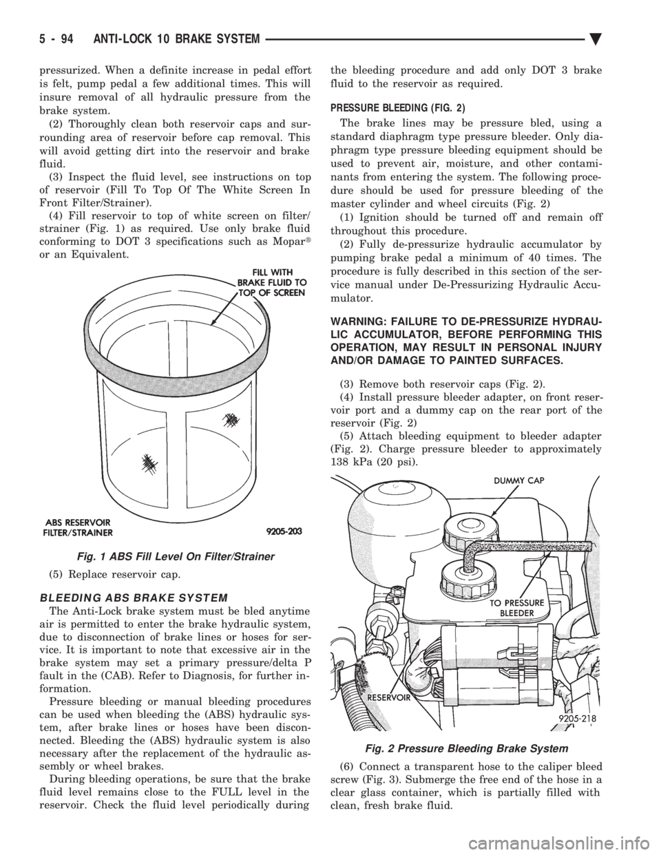
Front Filter/Strainer). (4) Fill reservoir to top of white screen on filter/
strainer (Fig. 1) as required. Use only brake fluid
conforming to DOT 3 specifications such as Mopar t
or an Equivalent.
(5) Replace reservoir cap.
BLEEDING ABS BRAKE SYSTEM
The Anti-Lock brake system must be bled anytime
air is permitted to enter the brake hydraulic system,
due to disconnection of brake lines or hoses for ser-
vice. It is important to note that excessive air in the
brake system may set a primary pressure/delta P
fault in the (CAB). Refer to Diagnosis, for further in-
formation. Pressure bleeding or manual bleeding procedures
can be used when bleeding the (ABS) hydraulic sys-
tem, after brake lines or hoses have been discon-
nected. Bleeding the (ABS) hydraulic system is also
necessary after the replacement of the hydraulic as-
sembly or wheel brakes. During bleeding operations, be sure that the brake
fluid level remains close to the FULL level in the
reservoir. Check the fluid level periodically during the bleeding procedure and add only DOT 3 brake
fluid to the reservoir as required.
PRESSURE BLEEDING (FIG. 2)
The brake lines may be pressure bled, using a
standard diaphragm type pressure bleeder. Only dia-
phragm type pressure bleeding equipment should be
used to prevent air, moisture, and other contami-
nants from entering the system. The following proce-
dure should be used for pressure bleeding of the
master cylinder and wheel circuits (Fig. 2) (1) Ignition should be turned off and remain off
throughout this procedure. (2) Fully de-pressurize hydraulic accumulator by
pumping brake pedal a minimum of 40 times. The
procedure is fully described in this section of the ser-
vice manual under De-Pressurizing Hydraulic Accu-
mulator.
WARNING: FAILURE TO DE-PRESSURIZE HYDRAU-
LIC ACCUMULATOR, BEFORE PERFORMING THIS
OPERATION, MAY RESULT IN PERSONAL INJURY
AND/OR DAMAGE TO PAINTED SURFACES.
(3) Remove both reservoir caps (Fig. 2).
(4) Install pressure bleeder adapter, on front reser-
voir port and a dummy cap on the rear port of the
reservoir (Fig. 2) (5) Attach bleeding equipment to bleeder adapter
(Fig. 2). Charge pressure bleeder to approximately
138 kPa (20 psi).
(6) Connect a transparent hose to the caliper bleed
screw (Fig. 3). Submerge the free end of the hose in a
clear glass container, which is partially filled with
clean, fresh brake fluid.
Fig. 1 ABS Fill Level On Filter/Strainer
Fig. 2 Pressure Bleeding Brake System
5 - 94 ANTI-LOCK 10 BRAKE SYSTEM Ä