1993 CHEVROLET PLYMOUTH ACCLAIM air filter
[x] Cancel search: air filterPage 1871 of 2438
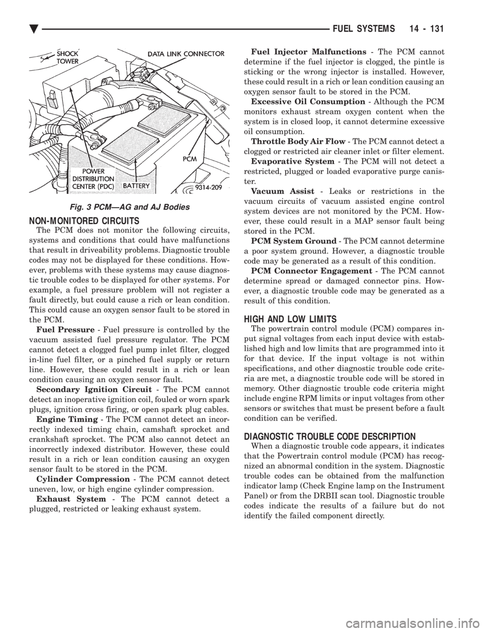
NON-MONITORED CIRCUITS
The PCM does not monitor the following circuits,
systems and conditions that could have malfunctions
that result in driveability problems. Diagnostic trouble
codes may not be displayed for these conditions. How-
ever, problems with these systems may cause diagnos-
tic trouble codes to be displayed for other systems. For
example, a fuel pressure problem will not register a
fault directly, but could cause a rich or lean condition.
This could cause an oxygen sensor fault to be stored in
the PCM. Fuel Pressure - Fuel pressure is controlled by the
vacuum assisted fuel pressure regulator. The PCM
cannot detect a clogged fuel pump inlet filter, clogged
in-line fuel filter, or a pinched fuel supply or return
line. However, these could result in a rich or lean
condition causing an oxygen sensor fault. Secondary Ignition Circuit - The PCM cannot
detect an inoperative ignition coil, fouled or worn spark
plugs, ignition cross firing, or open spark plug cables. Engine Timing - The PCM cannot detect an incor-
rectly indexed timing chain, camshaft sprocket and
crankshaft sprocket. The PCM also cannot detect an
incorrectly indexed distributor. However, these could
result in a rich or lean condition causing an oxygen
sensor fault to be stored in the PCM. Cylinder Compression - The PCM cannot detect
uneven, low, or high engine cylinder compression. Exhaust System - The PCM cannot detect a
plugged, restricted or leaking exhaust system. Fuel Injector Malfunctions
- The PCM cannot
determine if the fuel injector is clogged, the pintle is
sticking or the wrong injector is installed. However,
these could result in a rich or lean condition causing an
oxygen sensor fault to be stored in the PCM. Excessive Oil Consumption - Although the PCM
monitors exhaust stream oxygen content when the
system is in closed loop, it cannot determine excessive
oil consumption. Throttle Body Air Flow - The PCM cannot detect a
clogged or restricted air cleaner inlet or filter element. Evaporative System - The PCM will not detect a
restricted, plugged or loaded evaporative purge canis-
ter. Vacuum Assist - Leaks or restrictions in the
vacuum circuits of vacuum assisted engine control
system devices are not monitored by the PCM. How-
ever, these could result in a MAP sensor fault being
stored in the PCM. PCM System Ground - The PCM cannot determine
a poor system ground. However, a diagnostic trouble
code may be generated as a result of this condition. PCM Connector Engagement - The PCM cannot
determine spread or damaged connector pins. How-
ever, a diagnostic trouble code may be generated as a
result of this condition.
HIGH AND LOW LIMITS
The powertrain control module (PCM) compares in-
put signal voltages from each input device with estab-
lished high and low limits that are programmed into it
for that device. If the input voltage is not within
specifications, and other diagnostic trouble code crite-
ria are met, a diagnostic trouble code will be stored in
memory. Other diagnostic trouble code criteria might
include engine RPM limits or input voltages from other
sensors or switches that must be present before a fault
condition can be verified.
DIAGNOSTIC TROUBLE CODE DESCRIPTION
When a diagnostic trouble code appears, it indicates
that the Powertrain control module (PCM) has recog-
nized an abnormal condition in the system. Diagnostic
trouble codes can be obtained from the malfunction
indicator lamp (Check Engine lamp on the Instrument
Panel) or from the DRBII scan tool. Diagnostic trouble
codes indicate the results of a failure but do not
identify the failed component directly.
Fig. 3 PCMÐAG and AJ Bodies
Ä FUEL SYSTEMS 14 - 131
Page 1902 of 2438
3.3L AND 3.8L MULTI-PORT FUEL INJECTIONÐON-BOARD DIAGNOSTICS INDEX
page page
60-Way Pcm Wiring Connector ............. 167
Circuit Actuation Test Mode ................ 166
Diagnostic Trouble Code Description ......... 163
General Information ...................... 162
High and Low Limits ..................... 163
Monitored Circuits ....................... 162 Non-Monitored Circuits
................... 162
State Display Test Mode .................. 163
System Tests .......................... 163
Throttle Body Minimum Air Flow Check Procedure ............................ 166
GENERAL INFORMATION
The powertrain control module (PCM) has been
programmed to monitor many different circuits of the
fuel injection system. If a problem is sensed with a
monitored circuit often enough to indicate an actual
problem, the PCM stores a fault. If the problem is re-
paired or ceases to exist, the PCM cancels the Diag-
nostic trouble code after 51 vehicle key on/off cycles. Certain criteria must be met for a diagnostic trou-
ble code to be entered into the PCM memory. The
criteria may be a specific range of engine RPM, en-
gine temperature, and/or input voltage to the PCM. It is possible a diagnostic trouble code for a moni-
tored circuit may not be entered into memory even
though a malfunction has occurred. This may happen
because one of the diagnostic trouble code criteria for
the circuit has not been met. For example, assume
one of the diagnostic trouble code criteria for a sen-
sor circuit is the engine must be operating between
750 and 2000 RPM. If the sensor output circuit
shorts to ground when engine RPM is above 2400
RPM (resulting i n a 0 volt input to the PCM) a diag-
nostic trouble code will not be entered into memory.
This is because the condition does not occur within
the specified RPM range. There are several operating conditions that the
PCM does not monitor and set diagnostic trouble
codes for. Refer to Monitored Circuits and Non-Mon-
itored Circuits in this section. Stored diagnostic trouble codes can be displayed ei-
ther by cycling the ignition key On - Off - On - Off -
On, or through use of the DRBII scan tool. The
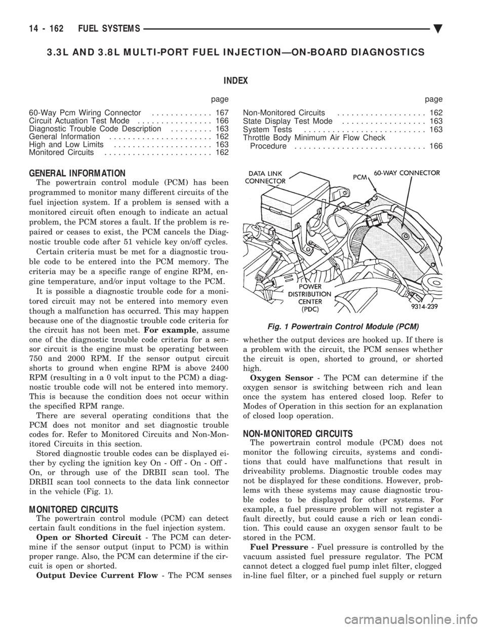
DRBII scan tool connects to the data link connector
in the vehicle (Fig. 1).
MONITORED CIRCUITS
The powertrain control module (PCM) can detect
certain fault conditions in the fuel injection system. Open or Shorted Circuit - The PCM can deter-
mine if the sensor output (input to PCM) is within
proper range. Also, the PCM can determine if the cir-
cuit is open or shorted. Output Device Current Flow - The PCM senses whether the output devices are hooked up. If there is
a problem with the circuit, the PCM senses whether
the circuit is open, shorted to ground, or shorted
high. Oxygen Sensor - The PCM can determine if the
oxygen sensor is switching between rich and lean
once the system has entered closed loop. Refer to
Modes of Operation in this section for an explanation
of closed loop operation.
NON-MONITORED CIRCUITS
The powertrain control module (PCM) does not
monitor the following circuits, systems and condi-
tions that could have malfunctions that result in
driveability problems. Diagnostic trouble codes may
not be displayed for these conditions. However, prob-
lems with these systems may cause diagnostic trou-
ble codes to be displayed for other systems. For
example, a fuel pressure problem will not register a
fault directly, but could cause a rich or lean condi-
tion. This could cause an oxygen sensor fault to be
stored in the PCM. Fuel Pressure - Fuel pressure is controlled by the
vacuum assisted fuel pressure regulator. The PCM
cannot detect a clogged fuel pump inlet filter, clogged
in-line fuel filter, or a pinched fuel supply or return
Fig. 1 Powertrain Control Module (PCM)
14 - 162 FUEL SYSTEMS Ä
Page 1903 of 2438
line. However, these could result in a rich or lean
condition causing an oxygen sensor fault to be stored in
the PCM. Secondary Ignition Circuit - The PCM cannot
detect an inoperative ignition coil, fouled or worn spark
plugs, ignition cross firing, or open spark plug cables. Engine Timing - The PCM cannot detect an incor-
rectly indexed timing chain, camshaft sprocket and
crankshaft sprocket. However, these could result in a
rich or lean condition causing an oxygen sensor fault to
be stored in the PCM. Cylinder Compression - The PCM cannot detect
uneven, low, or high engine cylinder compression. Exhaust System - The PCM cannot detect a
plugged, restricted or leaking exhaust system. Fuel Injector Malfunctions - The PCM cannot
determine if a fuel injector is clogged, the needle is
sticking or the wrong injector is installed. However,
these could result in a rich or lean condition causing an
oxygen sensor fault to be stored in the PCM. Excessive Oil Consumption - Although the PCM
monitors exhaust stream oxygen content when the
system is in closed loop, it cannot determine excessive
oil consumption. Throttle Body Air Flow - The PCM cannot detect a
clogged or restricted air cleaner inlet or filter element. Evaporative System - The PCM will not detect a
restricted, plugged or loaded evaporative purge canis-
ter. Vacuum Assist - Leaks or restrictions in the
vacuum circuits of vacuum assisted engine control
system devices are not monitored by the PCM. How-
ever, these could result in a MAP sensor fault being
stored in the PCM. PCM System Ground - The PCM cannot determine
a poor system ground. However, a diagnostic trouble
code may be generated as a result of this condition. PCM Connector Engagement - The PCM cannot
determine spread or damaged connector pins. How-
ever, a diagnostic trouble code may be generated as a
result of this condition.
HIGH AND LOW LIMITS
The powertrain control module (PCM) compares in-
put signal voltages from each input device with estab-
lished high and low limits for the device. If the input
voltage is not within limits and other diagnostic
trouble code criteria are met, a diagnostic trouble code
will be stored in memory. Other diagnostic trouble code
criteria might include engine RPM limits or input
voltages from other sensors or switches that must be
present before a fault condition can be verified.
DIAGNOSTIC TROUBLE CODE DESCRIPTION
A diagnostic trouble code indicates that the power-
train control module (PCM) has recognized an abnor- mal condition in the system. Diagnostic trouble codes
can be obtained from the malfunction indicator lamp
(Check Engine lamp on the instrument panel) or from
the DRBII scan tool. Diagnostic trouble codes indicate
the results of a failure but do not identify the failed
component directly.
SYSTEM TESTS
WARNING: APPLY PARKING BRAKE AND/OR BLOCK
WHEELS BEFORE PERFORMING ANY TEST ON AN
OPERATING ENGINE.
OBTAINING DIAGNOSTIC TROUBLE CODES
(1) Connect the DRBII scan tool to the data link
connector located in the engine compartment near the
driver side strut tower (Fig. 1). (2) Start the engine if possible, cycle the transaxle
selector and the A/Cswitch if applicable. Shut off the
engine. (3) Turn the ignition switch on, access Read Fault
Screen. Record all the fault messages shown on the
DRBII scan tool. Observe the malfunction indicator
lamp (check engine lamp on the instrument panel). The
lamp should light for 2 seconds then go out (bulb
check). Diagnostic trouble code erasure; access erase
diagnostic trouble code data
STATE DISPLAY TEST MODE
The switch inputs used by the powertrain control
module (PCM) have only two recognized states, HIGH
and LOW. For this reason, the PCM cannot recognize
the difference between a selected switch position ver-
sus an open circuit, a short circuit, or a defective
switch. If the change is displayed, it can be assumed
that the entire switch circuit to the PCM is functional.
From the state display screen access either State
Display Inputs and Outputs or State Display Sensors.
STATE DISPLAY INPUTS AND OUTPUTS
Connect the DRBII scan tool to the vehicle and access
the State Display screen. Then access Inputs and
Outputs. The following is a list of the engine control
system functions accessible through the Inputs and
Outputs screen. Park/Neutral Switch
Speed Control Resume
Brake Switch
Speed Control On/Off
Speed Control Set
A/C Switch Sense
S/C Vent Solenoid
Ä FUEL SYSTEMS 14 - 163
Page 1909 of 2438
3.3L AND 3.8L MULTI-PORT FUEL INJECTIONÐSERVICE PROCEDURES INDEX
page page
Camshaft Position Sensor Service ........... 176
Crankshaft Position Sensor ................ 176
EVAP Canister Purge Solenoid Service ....... 175
Fuel Injector ........................... 174
Fuel Injector Rail Assembly ................ 170
Fuel Pressure Regulator .................. 173
Fuel System Pressure Release Procedure ..... 169 Heated Oxygen Sensor (O
2Sensor) Service . . . 177
Idle Air Control Motor .................... 170
Manifold Absolute Pressure (MAP) Sensor ..... 175
PCM Service ........................... 175
Throttle Body ........................... 169
Throttle Body Removal ................... 169
Throttle Position Sensor .................. 169
THROTTLE BODY REMOVAL
(1) Disconnect negative battery cable.
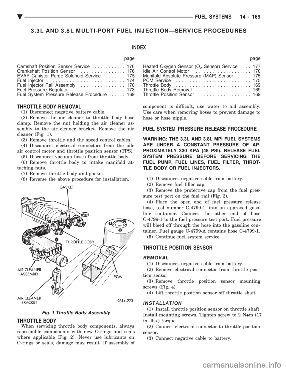
(2) Remove the air cleaner to throttle body hose
clamp. Remove the nut holding the air cleaner as-
sembly to the air cleaner bracket. Remove the air
cleaner (Fig. 1). (3) Remove throttle and the speed control cables.
(4) Disconnect electrical connectors from the idle
air control motor and throttle position sensor (TPS). (5) Disconnect vacuum hoses from throttle body.
(6) Remove throttle body to intake manifold at-
taching nuts. (7) Remove throttle body and gasket.
(8) Reverse the above procedure for installation.
THROTTLE BODY
When servicing throttle body components, always
reassemble components with new O-rings and seals
where applicable (Fig. 2). Never use lubricants on
O-rings or seals, damage may result. If assembly of component is difficult, use water to aid assembly.
Use care when removing hoses to prevent damage to
hose or hose nipple.
FUEL SYSTEM PRESSURE RELEASE PROCEDURE
WARNING: THE 3.3L AND 3.8L MPI FUEL SYSTEMS
ARE UNDER A CONSTANT PRESSURE OF AP-
PROXIMATELY 330 KPA (48 PSI). RELEASE FUEL
SYSTEM PRESSURE BEFORE SERVICING THE
FUEL PUMP, FUEL LINES, FUEL FILTER, THROT-
TLE BODY OR FUEL INJECTORS.
(1) Disconnect negative cable from battery.
(2) Remove fuel filler cap.
(3) Remove the protective cap from the fuel pres-
sure test port on the fuel rail (Fig. 3). (4) Place the open end of fuel pressure release
hose, tool number C-4799-1, into an approved gaso-
line container. Connect the other end of hose
C-4799-1 to the fuel pressure test port. Fuel pressure
will bleed off through the hose into the gasoline con-
tainer. Fuel gauge C-4799-A contains hose C-4799-1. (5) Continue fuel system service.
THROTTLE POSITION SENSOR
REMOVAL
(1) Disconnect negative cable from battery.
(2) Remove electrical connector from throttle posi-
tion sensor. (3) Remove throttle position sensor mounting
screws (Fig. 4). (4) Lift throttle position sensor off throttle shaft.
INSTALLATION
(1) Install throttle position sensor on throttle shaft.
Install mounting screws. Tighten screw to 2 N Im (17
in. lbs.) torque. (2) Connect electrical connector to throttle position
sensor. (3) Connect negative cable to battery.Fig. 1 Throttle Body Assembly
Ä FUEL SYSTEMS 14 - 169
Page 1995 of 2438
THREE SPEED TORQUEFLITE AUTOMATIC TRANSAXLE INDEX
page page
Accumulator-Recondition ................... 67
Aluminum Thread Repair ................... 48
Assembly Subassembly Installation ........... 57
Band Adjustment ......................... 47
Bearing Adjustment Procedures .............. 81
Clutch and Servo Air Pressure Tests .......... 43
Differential Repair ........................ 76
Disassembly Subassembly Removal .......... 50
Fluid and Filter Change .................... 40
Fluid Drain and Refill ..................... 40
Fluid Leakage-Transaxle Torque Converter Housing Area .......................... 44
Fluid Level and Condition .................. 40
Front Clutch-Recondition ................... 62
Front Planetary & Annulus Gear-Recondition .... 65
Gearshift Linkage Adjustment ............... 46
General Information ....................... 35
Governor ............................... 48
Hydraulic Control Pressure Adjustments ....... 47
Hydraulic Pressure Tests ................... 42
Kickdown Servo (Controlled Load)-Recondition . . 67 Low/Reverse Servo-Recondition
.............. 66
Oil Cooler Flow Check .................... 48
Oil Coolers and Tubes Reverse Flushing ...... 48
Oil Pump-Recondition ..................... 62
Output Shaft Repair ...................... 71
Park/Neutral Position and Back-Up Lamp Switch . 47
Parking Pawl ............................ 71
Pump Oil Seal-Replacement ................ 61
Rear Clutch-Recondition ................... 64
Road Test .............................. 40
Selection of Lubricant ..................... 40
Special Additives ......................... 40
Three Speed Torqueflite General Diagnosis ..... 36
Throttle Pressure Linkage Adjustment ......... 46
Torque Converter Clutch Solenoid Wiring Connector ............................ 40
Transaxle and Torque Converter Removal ...... 48
Transfer Shaft Repair ..................... 68
Valve Body-Recondition .................... 57
Vehicle Speed Sensor Pinion Gear ........... 47
GENERAL INFORMATION
Safety goggles should be worn at all times
when working on these transaxles. This transaxle combines a fully automatic 3 speed
transmission, final drive gearing, and differential into
a front wheel drive system. The unit is a Metric
design. The identification markings and usage of the
transaxle are charted in Diagnosis and Tests. Transaxle operation requirements are differ-
ent for each vehicle and engine combination and
some internal parts will be different to provide
for this. Therefore, when replacing parts, refer to
the seven digit part number stamped on rear of
the transaxle oil pan flange. Within this transaxle, there are 3 primary areas:
(1) Main center line plus valve body.
(2) Transfer shaft center line (includes governor and
parking sprag). (3) Differential center line. Center distances be-
tween the main rotating parts in these 3 areas are held
precise. This maintains a low noise level through
smooth accurate mesh of the gears. The torque converter, transaxle area, and differential
are housed in an integral aluminum die casting. The
differential oil sump is common with thetransaxle
sump. Separate filling of the differential is NOT nec-
essary. The torque converter is attached to the crankshaft
through a flexible driving plate. Cooling of the con-
verter is accomplished by circulating the transaxle
fluid through an oil-to-water type cooler located in the
radiator side tank and/or an oil-to air heat ex- changer. The torque converter assembly is a sealed
unit that cannot be disassembled.
The transaxle fluid is filtered by an internal filter
attached to the lower side of the valve body assem-
bly. Engine torque is transmitted to the torque con-
verter then, through the input shaft to multiple-disc
clutches in the transaxle. The power flow depends on
the application of the clutches and bands. Refer to
Elements in Use Chart in Diagnosis and Tests sec-
tion. The transaxle consists of two multiple-disc
clutches, an overrunning clutch, two servos, a hy-
draulic accumulator, two bands, and two planetary
gear sets. They provide three forward ratios and a re-
verse ratio. The common sun gear of the planetary
gear sets is connected to the front clutch by a driving
shell. The drive shell is splined to the sun gear and
to the front clutch retainer. The hydraulic system
consists of an oil pump, and a single valve body
which contains all of the valves except the governor
valves. The transaxle sump and differential sump are
both vented through the dipstick.Output torque
from the main center line is delivered through heli-
cal gears to the transfer shaft.This gear set is a
factor of the final drive (axle) ratio. The shaft also
carries the governor and parking sprag. An integral
helical gear on the transfer shaft drives the differen-
tial ring gear. The final drive gearing is completed
with one of three gear sets producing overall top gear
ratios of 2.78, 3.02, or 3.22 depending on model and
application.
Ä TRANSAXLE 21 - 35
Page 2000 of 2438
FLUID LEVEL AND CONDITION
The transmission and differential sump have a
common oil sump with a communicating opening
between the two. Before removing the dipstick, wipe all dirt off of the
protective disc and the dipstick handle. The torque converter will fill in both the PPark or N
Neutral positions. Place the selector lever in PPark to
check fluid level. Inspect fluid level on dipstick every six months.
Allow the engine to idle for at least one minute
with vehicle on level ground. This will assure
complete oil level stabilization between differen-
tial and transmission. A properly filled transaxle
will read near the addmark when fluid temperature is
21 degrees Celsius (70 degrees Fahrenheit). When the
transaxle reaches operating temperature the fluid
should be in the HOTregion.
Low fluid level can cause a variety of conditions
because it allows the pump to take in air along with the
fluid. As in any hydraulic system, air bubbles make the
fluid spongy, therefore, pressures will be low and build
up slowly. Improper filling can also raise the fluid level too
high. When the transaxle has too much fluid, the gears
churn up foam and cause the same conditions which
occur with a low fluid level. In either case, the air bubbles can cause overheating,
fluid oxidation, and varnishing, which can interfere
with normal valve, clutch, and servo operation. Foam-
ing can also result in fluid escaping from the transaxle
vent (dipstick handle) where it may be mistaken for a
leak. Along with fluid level, it is important to check the
condition of the fluid. When the fluid smells burned,
and is contaminated with metal or friction material
particles, a complete transaxle overhaul is needed. Be
sure to examine the fluid on the dipstick closely. If
there is any doubt about its condition, drain out a
sample for a double check. After the fluid has been checked, seat the dipstick
fully to seal out water and dirt.
SELECTION OF LUBRICANT
It is important that the proper lubricant be used in
these transmissions. MOPAR tATF PLUS (Automatic
Transmission Fluid-Type 7176) should be used to aid in
assuring optimum transmission performance. Fluids of
the type labeled DEXRON II Automatic Transmission
Fluid should be used only if the recommended fluid is
not available. It is important that the transmission
fluid be maintained at the prescribed level using the
recommended fluids.
SPECIAL ADDITIVES
Chrysler Corporation does not recommend the addi-
tion of any fluids to the transmission, other than the
automatic transmission fluid listed above. An ex- ception to this policy is the use of special dyes to aid in
detecting fluid leaks. The use of transmission sealers
should be avoided, since they may adversely affect
seals.
FLUID AND FILTER CHANGE
When the factory fill fluid is changed, only
fluids of the type labeled MOPAR tATF PLUS
(Automatic Transmission fluid) Type 7176 should
be used. A band adjustment and filter change
should be made at the time of the oil change. The
magnet (on the inside of the oil pan) should also
be cleaned with a clean, dry cloth. If the transaxle is disassembled for any reason,
the fluid and filter should be changed, and the
band(s) adjusted.
FLUID DRAIN AND REFILL
(1) Raise vehicle on a hoist (See Lubrication, Group
0). Place a drain container with a large opening, under
transaxle oil pan. (2) Loosen pan bolts and tap the pan at one corner to
break it loose allowing fluid to drain, then remove the
oil pan. (3) Install a new filter and gasket on bottom of the
valve body and tighten retaining screws to 5 N Im (40
in. lbs.). (4) Clean the oil pan and magnet. Reinstall pan
using new MOPAR tAdhesive sealant. Tighten oil pan
bolts to 19 N Im (165 in. lbs.).
(5) Pour four quarts of MOPAR tATF PLUS (Auto-
matic Transmission Fluid) Type 7176 through the
dipstick opening. (6) Start engine and allow to idle for at least one
minute. Then, with parking and service brakes ap-
plied, move selector lever momentarily to each posi-
tion, ending in the park or neutral position. (7) Add sufficient fluid to bring level to 1/8 inch
below the ADD mark. Recheck fluid level after transaxle is at normal
operating temperature. The level should be in the HOT
region (Fig. 1). To prevent dirt from entering transaxle, make cer-
tain that dipstick is full seated into the dipstick open-
ing.
TORQUE CONVERTER CLUTCH SOLENOID WIRING
CONNECTOR
If wiring connector is unplugged, the torque con-
verter clutch will not operate (Fig. 2).
ROAD TEST
Prior to performing a road test, be certain that the
fluid level and condition, and control cable adjustments
have been checked and approved. During the road test, the transaxle should be oper-
ated in each position to check for slipping and any
variation in shifting.
21 - 40 TRANSAXLE Ä
Page 2003 of 2438
(3) Move selector lever on transaxle one detent
forward from full rearward position. This is selector
2 position.
(4) Read pressures on both gauges as throttle lever
on transaxle is moved from full clockwise position to
full counterclockwise position. (5) Line pressure should read 52 to 58 psi with
throttle lever clockwise and gradually increase, as le-
ver is moved counterclockwise, to 80 to 88 psi. (6) Lubrication pressure should be 10 to 25 psi
with lever clockwise and 10 to 35 psi with lever full
counterclockwise. (7) This tests pump output, pressure regulation,
and condition of rear clutch and lubrication hydrau-
lic circuits.
TEST THREE (SELECTOR IN D)
(1) Attach gauges to lineandkickdown release
ports (Fig. 3). (2) Operate engine at 1600 rpm for test.
(3) Move selector lever on transaxle two detents
forward from full rearward position. This is selector
D position.
(4) Read pressures on both gauges as throttle lever
on transaxle is moved from full clockwise position to
full counterclockwise position. (5) Line pressure should read 52 to 58 psi with
throttle lever clockwise and gradually increase, as le-
ver is moved counterclockwise to 80 to 88 psi. (6) Kickdown release is pressurized only in direct
drive and should be same as line pressure within 3
psi, up to kickdown point. (7) This tests pump output, pressure regulation,
and condition of rear clutch, front clutch, and hy-
draulic circuits.
TEST FOUR (SELECTOR IN REVERSE)
(1) Attach 300 psi gauge to low-reverseport (Fig.
3). (2) Operate engine at 1600 rpm for test.
(3) Move selector lever on transaxle four detents
forward from full rearward position. This is selector
R position.
(4) Low-reverse pressure should read 180 to 220
psi with throttle lever clockwise and gradually in-
crease, as lever is moved counterclockwise to 260 to
300 psi. (5) This tests pump output, pressure regulation,
and condition of front clutch and rear servo hydraulic
circuits. (6) Move selector lever on transaxle to Dposition
to check that low-reverse pressure drops to zero. (7) This tests for leakage into rear servo, due to
case porosity, which can cause reverse band burn
out.
TEST RESULT INDICATIONS
(1) If proper line pressure, minimum to maximum, is
found in any one test, the pump and pressure regulator
are working properly. (2) Low pressure in D, 1, and 2but correct pressure
in Rindicates rear clutch circuit leakage.
(3) Low pressure in D and Rbut correct pressure in
1 indicates front clutch circuit leakage.
(4) Low pressure in R and 1but correct pressure in
2 indicates rear servo circuit leakage.
(5) Low line pressure in all positions indicates a
defective pump, a clogged filter, or a stuck pressure
regulator valve.
GOVERNOR PRESSURE
Test only if transaxle shifts at wrong vehicle speeds
when throttle cable is correctly adjusted. (1) Connect a 0-150 psi pressure gauge to governor
pressure take-off point, located at lower right side of
case, below differential cover (Fig. 3). (2) Operate transaxle in third gear to read pres-
sures. The governor pressure should respond smoothly
to changes in mph and should return to 0 to 3 psi when vehicle is stopped. High pressure at
standstill (above 3 psi) will prevent the transaxle from
downshifting.
THROTTLE PRESSURE
No gauge port is provided for throttle pressure.
Incorrect throttle pressure should only be suspected if
part throttle upshift speeds are either delayed or occur
too early, with a correctly adjusted throttle cable.
Engine runaway on either upshifts or downshifts can
also be an indicator of incorrect (low) throttle pressure
setting, or misadjusted throttle cable. In no case should throttle pressure be adjusted until
the transaxle throttle cable adjustment has been veri-
fied to be correct.
CLUTCH AND SERVO AIR PRESSURE TESTS
A no drive condition might exist even with correct
fluid pressure, because of inoperative clutches or
bands. The inoperative units, clutches, bands, and
servos can be located through a series of tests by
substituting air pressure for fluid pressure (Fig. 4). The front and rear clutches, kickdown servo, and
low-reverse servo may be tested by applying air pres-
sure to their respective passages after the valve body assembly has been removed. To make
air pressure tests, proceed as follows: Compressed air supply must be free of all dirt
or moisture. Use a pressure of 30 psi. Remove oil pan and valve body See Disassembly-
Subassembly Removal .
FRONT CLUTCH
Apply air pressure to front clutch applypassage and
listen for a dull thudwhich indicates that front
Ä TRANSAXLE 21 - 43
Page 2011 of 2438
washed in a suitable solvent, then dried by com-
pressed air. Do not wipe parts with shop towels. All
mating surfaces in the transaxles are accurately ma-
chined; therefore, careful handling of all parts must
be exercised to avoid nicks or burrs. Remove all old sealant before applying new MO-
PAR tAdhesive Sealant.
Use only MOPAR tAdhesive Sealant when install-
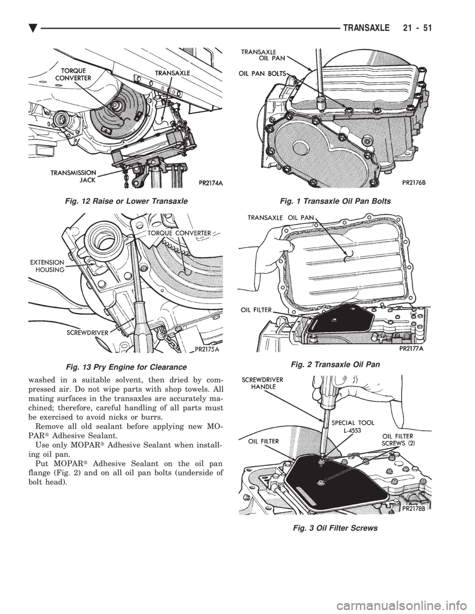
ing oil pan. Put MOPAR tAdhesive Sealant on the oil pan
flange (Fig. 2) and on all oil pan bolts (underside of
bolt head).
Fig. 12 Raise or Lower Transaxle
Fig. 13 Pry Engine for Clearance
Fig. 1 Transaxle Oil Pan Bolts
Fig. 2 Transaxle Oil Pan
Fig. 3 Oil Filter Screws
Ä TRANSAXLE 21 - 51