1993 CHEVROLET PLYMOUTH ACCLAIM headlamps
[x] Cancel search: headlampsPage 33 of 2438
COMPONENT AND SYSTEM INDEX
Name Group-page Name Group-page
AUDIO SYSTEM ............................ 8F-1
ANTENNAS ............................ 8F-20
COMPACT DISC PLAYER ................... 8F-30
RADIOS ............................... 8F-1
SPEAKERS ............................. 8F-24
BATTERY/STARTER/GENERATOR SERVICE ..........8B-1
BATTERY REMOVAL, INSTALLATION AND SERVICE . . 8B-1
GENERATOR ............................ 8B-9
SPECIFICATIONS ........................ 8B-12
STARTER .............................. 8B-4
BATTERY/STARTING/CHARGING SYSTEMS DIAGNOSTICS ........................... 8A-1
BATTERY TEST PROCEDURES ON-VEHICLE .......8A-3
FAULT CODESÐON BOARD DIAGNOSTICS .......8A-23
GENERAL INFORMATION .................... 8A-1
GENERATOR TEST PROCEDURES ON VEHICLE ....8A-19
IGNITION OFF DRAW (IOD) ..................8A-9
SPECIFICATIONS ........................ 8A-28
STARTER TEST PROCEDURES ON VEHICLE ......8A-11
CHIME WARNING/REMINDER SYSTEM ............8U-1
EMISSION CONTROL SYSTEMS .................25-1
EVAPORATIVE EMISSION CONTROLS ...........25-1
EXHAUST EMISSION CONTROLS ..............25-17
FUEL SYSTEMS ............................ 14-1
2.2L TURBO III MULTI-PORT FUEL INJECTIONÐ GENERAL DIAGNOSIS ................... 14-95
2.2L TURBO III MULTI-PORT FUEL INJECTIONÐ ON-BOARD DIAGNOSTICS ................14-100
2.2L TURBO III MULTI-PORT FUEL INJECTIONÐ SERVICE PROCEDURES .................14-107
2.2L TURBO III MULTI-PORT FUEL INJECTIONÐ SYSTEM OPERATION .................... 14-83
2.2L/2.5L SINGLE POINT FUEL INJECTIONÐ GENERAL DIAGNOSIS ................... 14-35
2.2L/2.5L SINGLE POINT FUEL INJECTIONÐ ON-BOARD DIAGNOSTICS .................14-41
2.2L/2.5L SINGLE POINT FUEL INJECTIONÐ SERVICE PROCEDURES .................. 14-48
2.2L/2.5L SINGLE POINT FUEL INJECTIONÐ SYSTEM OPERATION .................... 14-24
2.5L FLEXIBLE FUEL MULTI-PORT FUEL INJECTIONÐGENERAL DIAGNOSIS ..........14-66
2.5L FLEXIBLE FUEL MULTI-PORT FUEL INJECTIONÐON-BOARD DIAGNOSTICS ........14-70
2.5L FLEXIBLE FUEL MULTI-PORT FUEL INJECTIONÐSERVICE PROCEDURES .........14-77
2.5L FLEXIBLE FUEL MULTI-PORT FUEL INJECTIONÐSYSTEM OPERATION ...........14-55
3.0L MULTI-PORT FUEL INJECTIONÐGENERAL DIAGNOSIS .......................... 14-125
3.0L MULTI-PORT FUEL INJECTIONÐON-BOARD DIAGNOSTICS ........................ 14-130
3.0L MULTI-PORT FUEL INJECTIONÐSERVICE PROCEDURES ........................ 14-138
3.0L MULTI-PORT FUEL INJECTIONÐSYSTEM OPERATION ......................... 14-113
3.3L AND 3.8L MULTI-PORT FUEL INJECTIONÐ GENERAL DIAGNOSIS ................... 14-157 3.3L AND 3.8L MULTI-PORT FUEL INJECTIONÐ
ON-BOARD DIAGNOSTICS ................14-162
3.3L AND 3.8L MULTI-PORT FUEL INJECTIONÐ SERVICE PROCEDURES .................14-169
3.3L AND 3.8L MULTI-PORT FUEL INJECTIONÐ SYSTEM OPERATION ................... 14-145
ACCELERATOR PEDAL AND THROTTLE CABLE ....14-21
FUEL DELIVERY SYSTEM .................... 14-3
FUEL TANKS ........................... 14-14
GENERAL INFORMATION .................... 14-1
SPECIFICATIONS ........................ 14-178
HORNS ................................. 8G-1
IGNITION SYSTEMS ......................... 8D-1
2.2L TBI, 2.5L TBI, 2.5L MPI AND 3.0L IGNITION SYSTEMSÐDIAGNOSTIC PROCEDURES .......8D-11
2.2L TBI, 2.5L TBI, 2.5L MPI AND 3.0L IGNITION SYSTEMSÐSERVICE PROCEDURES ..........8D-14
2.2L TBI, 2.5L TBI, 2.5L MPI AND 3.0L IGNITION SYSTEMSÐSYSTEM OPERATION ............8D-1
2.2L TURBO III, 3.3L AND 3.8L IGNITION SYSTEMÐDIAGNOSTIC PROCEDURES ........8D-35
2.2L TURBO III, 3.3L AND 3.8L IGNITION SYSTEMÐSYSTEM OPERATION ............8D-24
2.2L TURBO III, 3.3L AND 3.8L IGNITION SYSTEMSÐSERVICE PROCEDURES ..........8D-39
IGNITION SWITCH ....................... 8D-45
SPECIFICATIONS ........................ 8D-47
INSTRUMENT PANEL AND GAUGES ...............8E-1
AA BODY .............................. 8E-1
AC AND AY BODIES ...................... 8E-23
AG AND AJ BODIES ...................... 8E-42
AP BODY ............................. 8E-58
LAMPS .................................. 8L-1
BULB APPLICATION TABLE ..................8L-38
CONCEALED HEADLAMPS ..................8L-27
EXTERIOR LAMP SWITCHES AND HEADLAMP ALIGNMENT ........................... 8L-3
EXTERIOR LAMP SYSTEMS .................8L-25
EXTERIOR LAMPSÐAA BODY ................8L-7
EXTERIOR LAMPSÐAC BODY ...............8L-10
EXTERIOR LAMPSÐAG BODY ...............8L-14
EXTERIOR LAMPSÐAJ BODY ................8L-16
EXTERIOR LAMPSÐAP BODY ...............8L-19
EXTERIOR LAMPSÐAY-BODY ................8L-22
GENERAL INFORMATION .................... 8L-1
ILLUMINATED ENTRY SYSTEM ...............8L-33
OVERHEAD CONSOLE ........................ 8C-1
AA BODY .............................. 8C-1
AC AND AY BODY ........................ 8C-6
AG AND AJ BODIES ...................... 8C-13
AP BODY ............................. 8C-21
POWER LOCKS ............................ 8P-1
POWER MIRRORS ..........................8T-1
POWER SEATS ............................ 8R-1
POWER WINDOWS .......................... 8S-1
REAR WINDOW DEFOGGER .................... 8N-1
RESTRAINT SYSTEMS ....................... 8M-1
TURN SIGNALS AND HAZARD WARNING FLASHER ....8J-1
VEHICLE SPEED CONTROL .................... 8H-1
Page 55 of 2438

CHASSIS AND BODY INDEX
page page
Body Lubrication ......................... 22
Brakes ................................ 21
Headlamps ............................. 22
Lower Ball Joints ......................... 19 Power Steering
.......................... 19
Rear Wheel Bearings ..................... 20
Steering Linkage ......................... 19
STEERING LINKAGE
INSPECTION
The steering linkage and steering gear should be in-
spected for wear, leaks or damage when other under ve-
hicle service is performed. The rack and pinion steering
gear end boots should not have excess oil or grease res-
idue on the outside surfaces or surrounding areas
(Fig.1). If boot is leaking, it should be repaired. For
proper service procedures, see Group 19, Steering.
The tie rod end seal should fit securely between the
steering knuckle and tie rod end (Fig.2). The steering
linkage should be lubricated at the time and distance
intervals described in the Lubrication and Mainte-
nance Schedules. Refer to General Information sec-
tion of this group.
TIE ROD END LUBRICATION
Lubricate the steering linkage with Mopar, Multi-
mileage Lube or equivalent. Using a wiping cloth,
clean grease and dirt from around grease fitting and
joint seal. Using a grease gun, fill tie rod end until
lubricant leaks from around the tie rod end side of
the seal (Fig.2). When lube operation is complete,
wipe off excess grease.
LOWER BALL JOINTS
INSPECTION
The front suspension lower ball joints should be in-
spected for wear, leaks or damage when other under ve- hicle service is performed. The ball joint seal should fit
securely between the steering knuckle and lower control
arm (Fig. 3). The ball joints should be lubricated at the
time and distance intervals described in the Lubrication
and Maintenance Schedules. Refer to the General Infor-
mation section of this group.
BALL JOINT LUBRICATION
CAUTION: Do not over fill ball joint with grease,
damage to seal can result.
Lubricate the ball joints with Mopar, Multi-mile-
age Lube or equivalent. Using a wiping cloth, clean
grease and dirt from around grease fitting and joint
seal. Using a grease gun, fill ball joint until seal
starts to swell (Fig. 3). When lube operation is com-
plete, wipe off excess grease.
POWER STEERING
The power steering fluid level should be inspected
when other under hood service is performed. If the
fluid level is low and system is not leaking, use Mo-
par, Power Steering Fluid or equivalent. The power
steering system should be inspected for leaks when
other under vehicle service is performed. For proper
service procedures, refer to Group 19, Steering.Fig. 1 Inspect Steering Linkage
Fig. 2 Tie Rod End Lubrication
Ä LUBRICATION AND MAINTENANCE 0 - 19
Page 58 of 2438

BRAKE RESERVOIR LEVEL INSPECTION
WARNING: DO NOT ALLOW PETROLEUM OR WATER
BASE LIQUIDS TO CONTAMINATE BRAKE FLUID,
SEAL DAMAGE AND BRAKE FAILURE CAN RESULT.
RELIEVE PRESSURE IN ANTI-LOCK BRAKE SYS-
TEM BEFORE ADDING BRAKE FLUID TO RESER-
VOIR. IF NOT, BRAKE FLUID COULD DISCHARGED
FROM THE RESERVOIR POSSIBLY CAUSING PER-
SONAL INJURY.
The brake reservoir level should be inspected when
other under hood service is performed. It is normal
for the reservoir level to drop as disc brake pads
wear. When fluid must be added, use Mopar, Brake
Fluid or equivalent. Use only brake fluid conforming
to DOT 3, Federal, Department of Transportation
specification. To avoid brake fluid contamination, use
fluid from a properly sealed container. On vehicles with anti-lock brakes, depressurize the
system before inspecting fluid level. Turn OFF the
ignition and remove the key. Pump the brake pedal
at least 50 times to relieve the pressure in the sys-
tem.
On all vehicles, if fluid should become low after sev-
eral thousand kilometers (miles), fill the reservoir to
level marks on the side of the reservoir (Fig. 8 or 9).
HEADLAMPS
The headlamps should be inspected for intensity
and aim whenever a problem is suspected. When lug-
gage compartment is heavily loaded, the headlamp
aim should be adjusted to compensate for vehicle
height change. For proper service procedures, refer to
Group 8L, Lamps. DRIVER SUPPLEMENTAL AIRBAG SYSTEM
If the AIRBAG indicator lamp does not light at all,
stays lit or lights momentarily or continuously while
driving, a malfunction may have occurred. Prompt service is required. Refer to Group 8M, Restraint
Systems for proper diagnostic procedures.
BODY LUBRICATION
Body mechanisms and linkages should be inspected,
cleaned and lubricated as required to maintain ease of
operation and to prevent corrosion and wear. Before a component is lubricated, oil, grease and dirt
should be wiped off. If necessary, use solvent to clean
component to be lubricated. After lubrication is com-
plete, wipe off excess grease or oil. During winter season, external lock cylinders should
be lubricated with Mopar, Lock Lubricant or equiva-
lent to ensure proper operation when exposed to water
and ice. To assure proper hood latching component operation,
use engine oil to lubricate the lock, safety catch and
hood hinges when other under hood service is per-
formed. Mopar, Multi-purpose Grease or equivalent
should be applied sparingly to all pivot and slide
contact areas.
USE ENGINE OIL ON:
² Door hingesÐHinge pin and pivot points.
² Hood hingesÐPivot points.
² Luggage compartment lid hingesÐPivot points.
USE MOPAR LUBRIPLATE OR EQUIVALENT ON:
² Door check straps.
² Hood counterbalance springs.
² Luggage compartment lid latches.
² Luggage compartment lid prop rod pivots.
² Ash tray slides.
² Fuel Fill Door latch mechanism.
² Park brake mechanism.
² Front seat tracks.
Fig. 8 Anti-lock Brake Reservoir
Fig. 9 Master Cylinder Brake ReservoirÐExcept
Anti-lock
0 - 22 LUBRICATION AND MAINTENANCE Ä
Page 515 of 2438
AC AND AY BODIES INDEX
page page
Electronic Cluster ........................ 34
Gauges ................................ 28
General Information ....................... 23
Interior Lamp Replacement ................. 41 Mechanical Cluster and Gauge Service
........ 24
Mechanical/Electronic Cluster Removal ........ 25
Switch and Panel Component Service ......... 37
GENERAL INFORMATION
MECHANICAL CLUSTER
The mechanical cluster includes a fuel, oil pres-
sure, coolant temperature, and voltmeter gauges. All
incorporate magnetic type gauges. When the ignition
switch is in the OFF position, the gauges will show a
reading; however, the readings are only accurate
when the ignition switch is in the ON position. The mechanical cluster also includes an electric
speedometer, driven by pulses from the vehicle speed
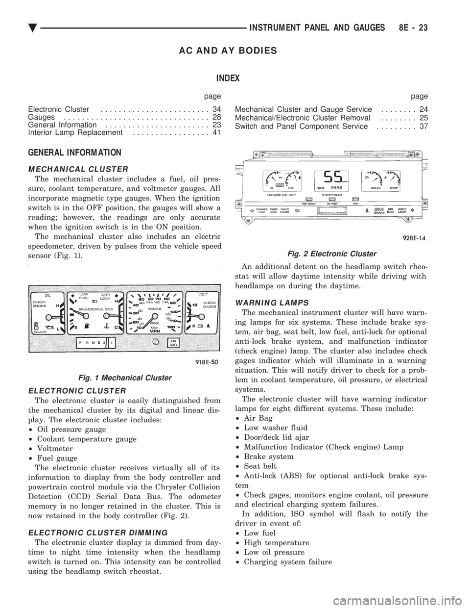
sensor (Fig. 1).
ELECTRONIC CLUSTER
The electronic cluster is easily distinguished from
the mechanical cluster by its digital and linear dis-
play. The electronic cluster includes:
² Oil pressure gauge
² Coolant temperature gauge
² Voltmeter
² Fuel gauge
The electronic cluster receives virtually all of its
information to display from the body controller and
powertrain control module via the Chrysler Collision
Detection (CCD) Serial Data Bus. The odometer
memory is no longer retained in the cluster. This is
now retained in the body controller (Fig. 2).
ELECTRONIC CLUSTER DIMMING
The electronic cluster display is dimmed from day-
time to night time intensity when the headlamp
switch is turned on. This intensity can be controlled
using the headlamp switch rheostat. An additional detent on the headlamp switch rheo-
stat will allow daytime intensity while driving with
headlamps on during the daytime.
WARNING LAMPS
The mechanical instrument cluster will have warn-
ing lamps for six systems. These include brake sys-
tem, air bag, seat belt, low fuel, anti-lock for optional
anti-lock brake system, and malfunction indicator
(check engine) lamp. The cluster also includes check
gages indicator which will illuminate in a warning
situation. This will notify driver to check for a prob-
lem in coolant temperature, oil pressure, or electrical
systems. The electronic cluster will have warning indicator
lamps for eight different systems. These include:
² Air Bag
² Low washer fluid
² Door/deck lid ajar
² Malfunction Indicator (Check engine) Lamp
² Brake system
² Seat belt
² Anti-lock (ABS) for optional anti-lock brake sys-
tem
² Check gages, monitors engine coolant, oil pressure
and electrical charging system failures. In addition, ISO symbol will flash to notify the
driver in event of:
² Low fuel
² High temperature
² Low oil pressure
² Charging system failure
Fig. 1 Mechanical Cluster
Fig. 2 Electronic Cluster
Ä INSTRUMENT PANEL AND GAUGES 8E - 23
Page 534 of 2438
AG AND AJ BODIES INDEX
page page
Cigar Lighter Removal ..................... 55
Cluster and Gauge Service and Testing ....... 43
Electronic Cluster ........................ 50
Electronic Vehicle Information Center (EVIC) .... 42
Engine Compartment Node ................. 55
Gauges ................................ 44 General Information
....................... 42
Instrument Panel Roll Down Procedure ........ 56
Interior Lamp Removal .................... 57
Mechanical/Electronic Cluster Removal ........ 43
Switch and Panel Component Service ......... 51
Switch Pod Assembly Removal .............. 43
GENERAL INFORMATION
CONVENTIONAL INSTRUMENT CLUSTER
The conventional instrument cluster incorporates
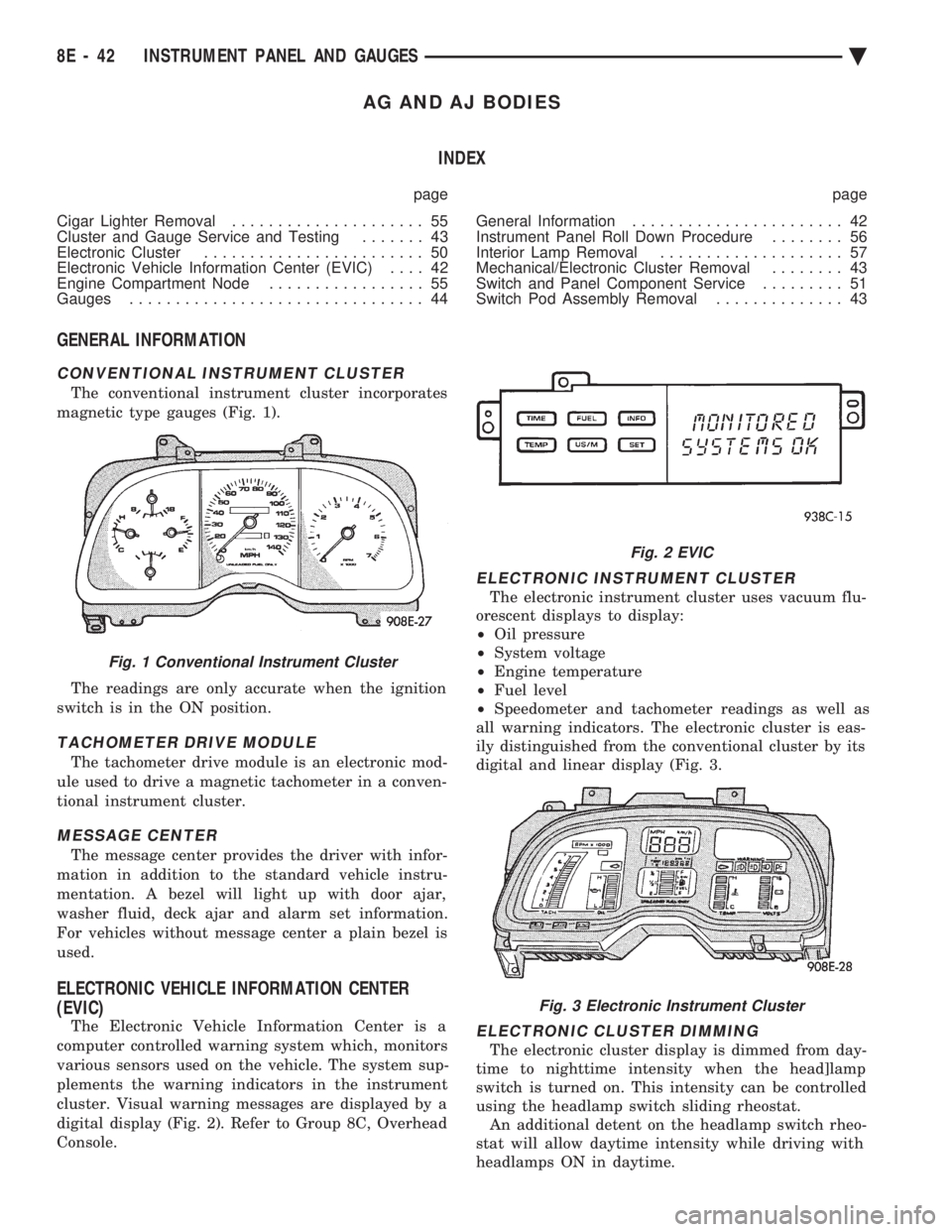
magnetic type gauges (Fig. 1).
The readings are only accurate when the ignition
switch is in the ON position.
TACHOMETER DRIVE MODULE
The tachometer drive module is an electronic mod-
ule used to drive a magnetic tachometer in a conven-
tional instrument cluster.
MESSAGE CENTER
The message center provides the driver with infor-
mation in addition to the standard vehicle instru-
mentation. A bezel will light up with door ajar,
washer fluid, deck ajar and alarm set information.
For vehicles without message center a plain bezel is
used.
ELECTRONIC VEHICLE INFORMATION CENTER
(EVIC)
The Electronic Vehicle Information Center is a
computer controlled warning system which, monitors
various sensors used on the vehicle. The system sup-
plements the warning indicators in the instrument
cluster. Visual warning messages are displayed by a
digital display (Fig. 2). Refer to Group 8C, Overhead
Console.
ELECTRONIC INSTRUMENT CLUSTER
The electronic instrument cluster uses vacuum flu-
orescent displays to display:
² Oil pressure
² System voltage
² Engine temperature
² Fuel level
² Speedometer and tachometer readings as well as
all warning indicators. The electronic cluster is eas-
ily distinguished from the conventional cluster by its
digital and linear display (Fig. 3.
ELECTRONIC CLUSTER DIMMING
The electronic cluster display is dimmed from day-
time to nighttime intensity when the head]lamp
switch is turned on. This intensity can be controlled
using the headlamp switch sliding rheostat. An additional detent on the headlamp switch rheo-
stat will allow daytime intensity while driving with
headlamps ON in daytime.
Fig. 1 Conventional Instrument Cluster
Fig. 2 EVIC
Fig. 3 Electronic Instrument Cluster
8E - 42 INSTRUMENT PANEL AND GAUGES Ä
Page 543 of 2438

Perform cluster Self Diagnostic Test to determine
whether problem is within cluster or outside of clus-
ter. Refer to Fig. 24 and 25.
Successful completion of the SELF DIAGNOSTIC
TEST indicates that the problem is in the wiring,
connectors or sensors out side of the cluster.
CLUSTER ASSEMBLY REMOVAL
The electronic cluster which is serviced as an as-
sembly is removed with the same procedure as the
conventional cluster.
CONDITION: CLUSTER DISPLAYS DO NOT ILLUMINATE AFTER VEHICLE IS STARTED
(1) Check fuses and verify battery and ignition
voltage at cluster connector. (2) Check ground from cluster connector to instru-
ment panel ground stud.
SWITCH AND PANEL COMPONENT SERVICE
HEADLAMP SWITCH
The headlamp switch is located on the left side of
the switch pod. The switch controls the headlamps,
parking lamps, fog lamps and instrument light dim- ming. If any of the switches require replacement the
entire headlamp switch assembly must be replaced
(Fig. 26 and 27).
REMOVAL
(1) Remove switch pod assembly from the instru-
ment panel. DO NOT attempt to remove instrument
cluster dimmer switch or wiper delay switch knob,
they are not removable. (2) Remove turn signal switch lever by pulling
straight out of switch pod. (3) Remove screws from bottom of switch pod.
(4) Separate inner and outer switch pod halves and
remove turn signal switch to gain access to screw. (5) Remove five inner switch pod panel screws and
3 screws from underneath the switch pod. Separate
the inner bezel from the outer bezel. (6) Remove switch mounting screws before discon-
necting linkage. (7) Disconnect switch linkage from buttons. Pull
the linkage straight up from the switch/button to dis-
engage it and remove switch.
Fig. 23 Mechanical Cluster Lamp Location
Ä INSTRUMENT PANEL AND GAUGES 8E - 51
Page 643 of 2438
LAMPS
CONTENTS
page page
BULB APPLICATION TABLE ............... 38
CONCEALED HEADLAMPS ................ 27
EXTERIOR LAMP SWITCHES AND HEADLAMP ALIGNMENT ........................... 3
EXTERIOR LAMP SYSTEMS .............. 25
EXTERIOR LAMPSÐAA BODY ............. 7
EXTERIOR LAMPSÐAC BODY ............ 10 EXTERIOR LAMPSÐAG BODY
............ 14
EXTERIOR LAMPSÐAJ BODY ............ 16
EXTERIOR LAMPSÐAP BODY ............ 19
EXTERIOR LAMPSÐAY-BODY ............ 22
GENERAL INFORMATION .................. 1
ILLUMINATED ENTRY SYSTEM ........... 33
GENERAL INFORMATION
Each vehicle is equipped with lamps used for illumi-
nating and indicating purposes. A circuit must have a
good ground to be complete. Circuit ground occurs
when the lamp socket makes contact with the metal
body. On vehicles with plastic lamps, a wire between
the socket and the body makes the grounds. When changing lamp bulbs, check the socket for
corrosion. If corrosion is present, clean contacts with a
wire brush and coat the inside of the socket with
Mopar tMulti-purpose Grease or equivalent.
CAUTION: Do not touch the glass of halogen bulbs
with fingers or any possibly oily surface, reduced
bulb life will result.
BODY IDENTIFICATION
Throughout this Group, references are made to the
vehicle family or body code. To decode the vehicle
identification plates, refer to the Introduction Section
at the front of this manual.
DIAGNOSTIC PROCEDURES
Begin electrical system failure diagnosis by testing
all related fuses and circuit breakers in the fuse block
and engine compartment. When a vehicle experiences problems with the head-
lamp system, verify the condition of the battery con-
nections, charging system, headlamp bulbs, wire con-
nectors, relay, high beam dimmer switch and headlamp
switch. Refer to Wiring Diagrams manual for compo-
nent locations and circuit information.
SYMPTOM
Headlamps are dim when engine is idling of
with ignition turned OFF. Canada cars must
have lamps ON. ACTION
² Clean battery terminal clamps and posts. Refer to
Group 8B, Battery/Starter/Generator Service for
proper procedures.
² Test charging system output. Refer to Group 8A,
Battery/Starting/Charging Systems Diagnostics for
proper testing procedures.
² Test for high resistance in headlamp circuits.
² Defective headlamp bulb.
SYMPTOM
Bulbs burn out frequently.
ACTION
² Test charging system output. Refer to Group 8A,
Battery/Starting/Charging Systems Diagnostics for
proper testing procedures.
² Check for loose or corroded connector terminals or
splices in headlamp circuits. Refer to Wiring Diagrams
manual for component and splice locations.
SYMPTOM
Headlamps are dim with engine running above
idle. Canada cars must have lamps ON.
ACTION
² Test charging system output. Refer to Group 8A,
Battery/Starting/Charging Systems Diagnostics for
proper testing procedures.
² Test for high resistance in headlamp circuits.
² Defective headlamp bulb.
SYMPTOM
Headlamps flash randomly.
ACTION
² Test for poor circuit ground.
² Test for high resistance in headlamp circuits.
Ä LAMPS 8L - 1
Page 644 of 2438
² Test condition of headlamp relay.
² Check for loose or corroded connector terminals or
splices in headlamp circuits. Refer to Wiring Dia-
grams manual for component and splice locations.
SYMPTOM
Headlamps do not illuminate.
ACTION
² Test for voltage at headlamp bulbs connectors.
² Test headlamp relay.
² Test headlamp switch.
² Test high-beam headlamp dimmer switch.
² Check for loose or corroded connector terminals or
splices in headlamp circuits. Refer to Wiring Dia-
grams manual for component and splice locations.
FOG LAMP DIAGNOSIS
The fog lamp system receives voltage from the
headlamp relay when the low-beam headlamps are turned ON. The high-beam headlamp dimmer switch
when actuated cancels out voltage feed to the fog
lamp circuit. The fog lamp circuit is protected by a
20 amp fuse located in the fuse panel. Refer to Wir-
ing Diagrams manual for component location and cir-
cuit information.
SYMPTOM
Fog lamps do not illuminate.
ACTION
² Test fog lamp bulb.
² Test for voltage at fog lamp connector.
² Test for proper fog lamp ground.
² Test circuit fuse.
² Test fog lamp switch.
² Test high-beam headlamp dimmer switch.
² Test headlamp relay.
² Test for open circuit in wire harness.
8L - 2 LAMPS Ä