1993 CHEVROLET PLYMOUTH ACCLAIM roof rack
[x] Cancel search: roof rackPage 420 of 2438
VARIANCE SETTING PROCEDURE
There are two methods for setting variance while
in variance set mode. If the CAL symbol is on proce-
dure 2 must be used.
PROCEDURE 1
(1) Turn ignition switch to the on position.
(2) Press and hold the Comp/Temp button till the
display is turned OFF. (3) While continuing to hold Comp/Temp button
depress and hold US/Metric button until the VAR
symbol lights in approximately 5 seconds. (4) Release buttons.
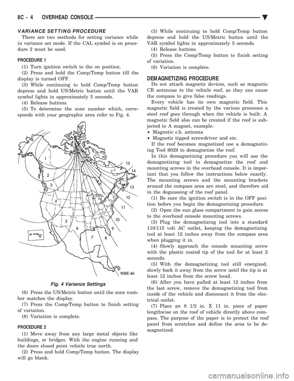
(5) To determine the zone number which, corre-
sponds with your geographic area refer to Fig. 4.
(6) Press the US/Metric button until the zone num-
ber matches the display. (7) Press the Comp/Temp button to finish setting
of variation. (8) Variation is complete.
PROCEDURE 2 (1) Move away from any large metal objects like
buildings, or bridges. With the engine running and
the doors closed point vehicle true north. (2) Press and hold Comp/Temp button. The display
will go blank. (3) While continuing to hold Comp/Temp button
depress and hold the US/Metric button until the
VAR symbol lights in approximately 5 seconds. (4) Release buttons.
(5) Press the Comp/Temp button to finish setting
of variation. (6) Variation is complete.
DEMAGNETIZING PROCEDURE
Do not attach magnetic devices, such as magnetic
CB antennas to the vehicle roof, as they can cause
the compass to give false readings. Every vehicle has its own magnetic field. This
magnetic field is created by the various processes a
steel roof goes through when the vehicle is built. A
magnetic field also can be created if the roof is sub-
jected to A magnet, example:
² Magnetic c.b. antenna
² Magnetic tipped screwdriver and etc.
If the roof becomes magnetized use a demagnetiz-
ing Tool 6029 to demagnetize the roof. In this demagnetizing procedure you will use the
demagnetizing tool to demagnetize the roof and
mounting screws in the overhead console. It is impor-
tant that you follow the instructions below exactly.
The mounting screws and the mounting brackets
around the compass area are steel, and therefore aid
in the degaussing of the roof panel. (1) Be sure the ignition switch is in the OFF posi-
tion before you begin the demagnetizing procedure. (2) Open the sun glass compartment to gain access
to the overhead console mounting screws. (3) Plug the demagnetizing tool into a standard
110/115 volt AC outlet, keeping the demagnetizing
tool at least 12 inches away from the compass area
when plugging it in. (4) Slowly approach the console mounting screw
with the plastic coated tip of the tool for at least 2
seconds. (5) With the demagnetizing tool still energized,
slowly back it away from the screw until the tip is at
least 12 inches from the screw head. (6) After you have pulled at least 12 inches from
the last screw, remove the demagnetizing tool from
inside of the vehicle and disconnect it from the elec-
trical outlet. (7) Place an 8 1/2 in. X 11 in. piece of paper
lengthwise on the roof of vehicle directly above com-
pass. The purpose of the paper is to protect the roof
panel from scratches and define the area to be de-
magnetized.
Fig. 4 Variance Settings
8C - 4 OVERHEAD CONSOLE Ä
Page 421 of 2438
(8) Plug in the demagnetizing tool, keeping it at
least 2 feet away from the compass unit. (9) Slowly approach the center of the roof panel at
the windshield with the demagnetizing tool plugged
in.
² Contact the roof panel with the tip of the tool.
² Using slow sweeping motions of 1/2 inch between
sweeps
² Move the tool approximately 4 inches either side of
the centerline, and at least 11 inches back from the
windshield. (10) With the demagnetizing tool still energized,
slowly back away from the roof panel until the tip is
at least two feet from the roof before unplugging the
tool. (11) Recalibrate compass.
COMPASS DIAGNOSTICS
To place the unit into the diagnostics mode, turn
the vehicle ignition off. Depress the Comp/Temp but-
ton while turning on the ignition/run switch. The
display will then show DO. There are three tests that
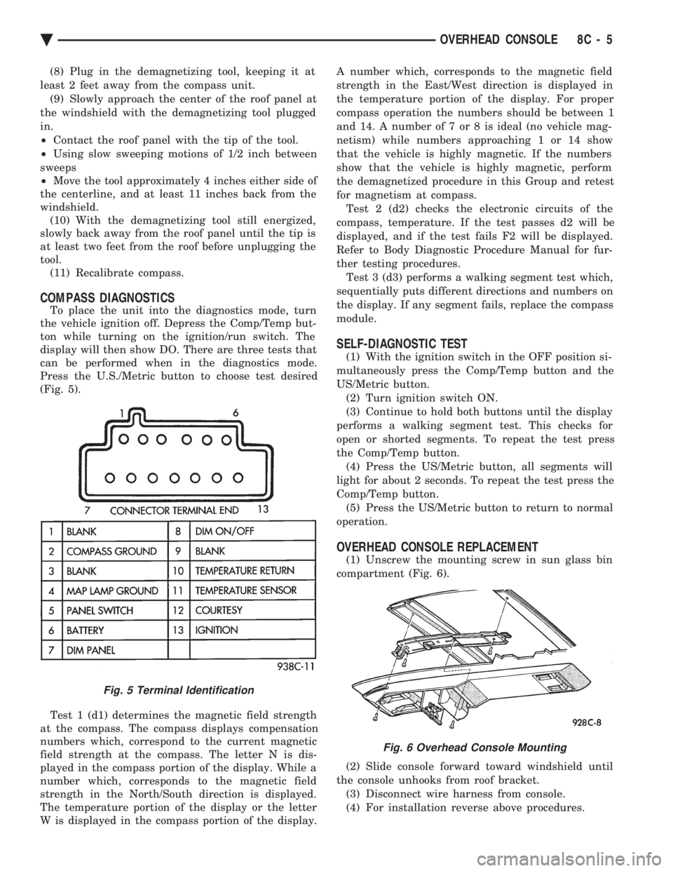
can be performed when in the diagnostics mode.
Press the U.S./Metric button to choose test desired
(Fig. 5).
Test 1 (d1) determines the magnetic field strength
at the compass. The compass displays compensation
numbers which, correspond to the current magnetic
field strength at the compass. The letter N is dis-
played in the compass portion of the display. While a
number which, corresponds to the magnetic field
strength in the North/South direction is displayed.
The temperature portion of the display or the letter
W is displayed in the compass portion of the display. A number which, corresponds to the magnetic field
strength in the East/West direction is displayed in
the temperature portion of the display. For proper
compass operation the numbers should be between 1
and 14. A number of 7 or 8 is ideal (no vehicle mag-
netism) while numbers approaching 1 or 14 show
that the vehicle is highly magnetic. If the numbers
show that the vehicle is highly magnetic, perform
the demagnetized procedure in this Group and retest
for magnetism at compass. Test 2 (d2) checks the electronic circuits of the
compass, temperature. If the test passes d2 will be
displayed, and if the test fails F2 will be displayed.
Refer to Body Diagnostic Procedure Manual for fur-
ther testing procedures. Test 3 (d3) performs a walking segment test which,
sequentially puts different directions and numbers on
the display. If any segment fails, replace the compass
module.
SELF-DIAGNOSTIC TEST
(1) With the ignition switch in the OFF position si-
multaneously press the Comp/Temp button and the
US/Metric button. (2) Turn ignition switch ON.
(3) Continue to hold both buttons until the display
performs a walking segment test. This checks for
open or shorted segments. To repeat the test press
the Comp/Temp button. (4) Press the US/Metric button, all segments will
light for about 2 seconds. To repeat the test press the
Comp/Temp button. (5) Press the US/Metric button to return to normal
operation.
OVERHEAD CONSOLE REPLACEMENT
(1) Unscrew the mounting screw in sun glass bin
compartment (Fig. 6).
(2) Slide console forward toward windshield until
the console unhooks from roof bracket. (3) Disconnect wire harness from console.
(4) For installation reverse above procedures.
Fig. 5 Terminal Identification
Fig. 6 Overhead Console Mounting
Ä OVERHEAD CONSOLE 8C - 5
Page 427 of 2438

MAP READING LAMPS/POWER SUNROOF SWITCH
REMOVAL
SWITCH REPLACEMENT
(1) Remove console, refer to Console Replacement.
(2) Disconnect switch wiring connector from re-
taining bracket. (3) Pry switch out of bezel snap tabs.
(4) Replace switch.
(5) For installation reverse above procedures.
LAMP/LENS REMOVAL
(1) Remove lens by inserting a flat blade tool into
slot located on the left side of lens. Pry lens to the
side and swing down as it unhooks from housing
(Fig. 4). (2) Replace lamp as necessary.
(3) Position lens with the center tabs on the left
side of lens snap into place. The lens are identified
with L and R on the reverse side. Do not reverse the
lens or it may damage the lens tabs.
POWER SUNROOF SWITCH/BEZEL REMOVAL
(1) Remove console, refer to Overhead Reading/
Courtesy Lamp Console Replacement. (2) Disconnect switch wiring connector from re-
taining bracket. (3) Pry switch out of bezel. Replace switch. If nec-
essary, push carefully at top closest to roof of bezel to
disengage trim bezel and pivot bezel out of housing. (4) Replace switch.
(5) For installation reverse above procedures.
OVERHEAD READING/COURTESY LAMP CONSOLE
The two reading/courtesy lamps are actuated by
pressing on the switch (Fig. 7):
² Courtesy lamps for when a door is opened
² Illuminated entry system is activated
² Headlamp switch is turned fully clockwise
The map lamp console also includes:
² A cubby storage bin. ²
Power sunroof switch, if equipped.
READING/COURTESY LAMP CONSOLE
REMOVAL
(1) Remove screws from visor tip-pin retainers.
(2) Slide console forward until free from retainer
bracket. (3) Disconnect wiring.
(4) For installation reverse above procedures. For
vehicles equipped with sunroof, avoid sliding console
to install. Install screws for console attachment and
push at rear of unit to snap over mounting bracket
for engagement.
LAMP/LENS REMOVAL
(1) Remove lens by inserting a flat blade tool be-
tween the round end of lamp lens and housing. Pry
lens from the housing. Pivot the lens and remove
(Fig. 7). (2) Replace lamp as necessary.
(3) Position lens into housing by locating lens
pivot and snap into place.
OVERHEAD CONSOLE WIRING HARNESS REMOVAL
(1) Remove console, refer to Overhead Reading/
Courtesy Lamp Console Removal. (2) Disconnect wiring connector from retaining
bracket. (3) Remove four screws attaching lamp housing to
console bezel. (4) Remove wiring and lamp housing.
(5) Remove lamp and replace assembly.
(6) For installation, reverse above procedures.
Fig. 6 EVIC Overhead Console Connector
Fig. 7 Reading/Courtesy Lamp Console
Ä OVERHEAD CONSOLE 8C - 11
Page 433 of 2438
(4) Drive the vehicle 1 to 3 complete circles. The
CAL light will then go off, showing the compass is
calibrated. If the compass portion of the display:
² It does not display.
² Readings are not accurate after calibration.
² The vehicle may have too much magnetism for the
compass to be accurate.
² The compass circuitry is not working properly.
² Refer to Variance Procedure, Demagnetizing Pro-
cedure and/or Compass Diagnostics.
VARIANCE PROCEDURE
Variance is the difference between magnetic North
and geographic North. In some areas the difference
between magnetic and geographic North is great
enough to cause the compass to give false readings. If
this occurs, the variance must be set. To set the variance, depress and hold down both
the Comp/Temp button and the U.S./Metric button.
The display will go off and after 5 seconds the VAR
light will come on. Release both buttons. Using the
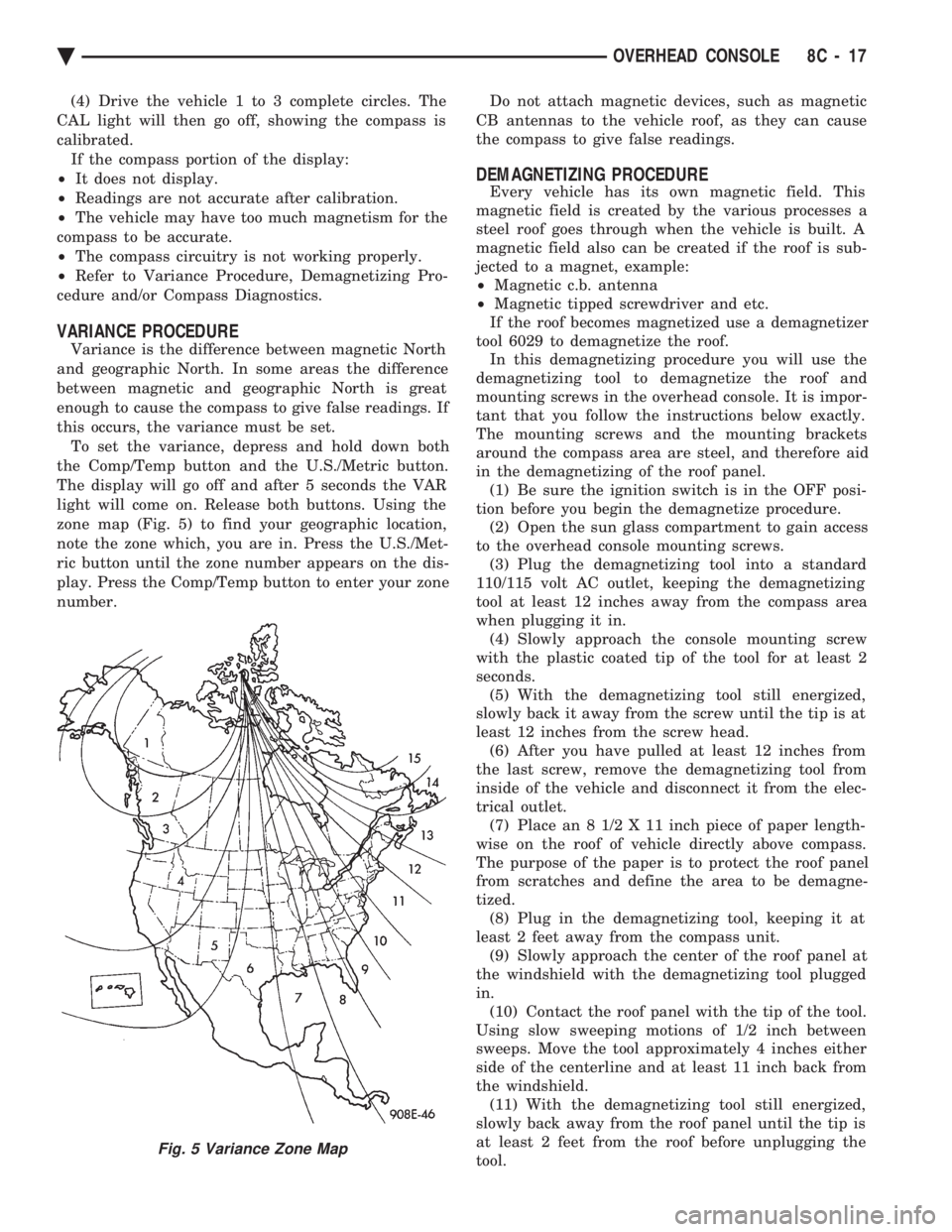
zone map (Fig. 5) to find your geographic location,
note the zone which, you are in. Press the U.S./Met-
ric button until the zone number appears on the dis-
play. Press the Comp/Temp button to enter your zone
number. Do not attach magnetic devices, such as magnetic
CB antennas to the vehicle roof, as they can cause
the compass to give false readings.
DEMAGNETIZING PROCEDURE
Every vehicle has its own magnetic field. This
magnetic field is created by the various processes a
steel roof goes through when the vehicle is built. A
magnetic field also can be created if the roof is sub-
jected to a magnet, example:
² Magnetic c.b. antenna
² Magnetic tipped screwdriver and etc.
If the roof becomes magnetized use a demagnetizer
tool 6029 to demagnetize the roof. In this demagnetizing procedure you will use the
demagnetizing tool to demagnetize the roof and
mounting screws in the overhead console. It is impor-
tant that you follow the instructions below exactly.
The mounting screws and the mounting brackets
around the compass area are steel, and therefore aid
in the demagnetizing of the roof panel. (1) Be sure the ignition switch is in the OFF posi-
tion before you begin the demagnetize procedure. (2) Open the sun glass compartment to gain access
to the overhead console mounting screws. (3) Plug the demagnetizing tool into a standard
110/115 volt AC outlet, keeping the demagnetizing
tool at least 12 inches away from the compass area
when plugging it in. (4) Slowly approach the console mounting screw
with the plastic coated tip of the tool for at least 2
seconds. (5) With the demagnetizing tool still energized,
slowly back it away from the screw until the tip is at
least 12 inches from the screw head. (6) After you have pulled at least 12 inches from
the last screw, remove the demagnetizing tool from
inside of the vehicle and disconnect it from the elec-
trical outlet. (7) Place an 8 1/2 X 11 inch piece of paper length-
wise on the roof of vehicle directly above compass.
The purpose of the paper is to protect the roof panel
from scratches and define the area to be demagne-
tized. (8) Plug in the demagnetizing tool, keeping it at
least 2 feet away from the compass unit. (9) Slowly approach the center of the roof panel at
the windshield with the demagnetizing tool plugged
in. (10) Contact the roof panel with the tip of the tool.
Using slow sweeping motions of 1/2 inch between
sweeps. Move the tool approximately 4 inches either
side of the centerline and at least 11 inch back from
the windshield. (11) With the demagnetizing tool still energized,
slowly back away from the roof panel until the tip is
at least 2 feet from the roof before unplugging the
tool.
Fig. 5 Variance Zone Map
Ä OVERHEAD CONSOLE 8C - 17
Page 436 of 2438
OVERHEAD CONSOLE REPLACEMENT
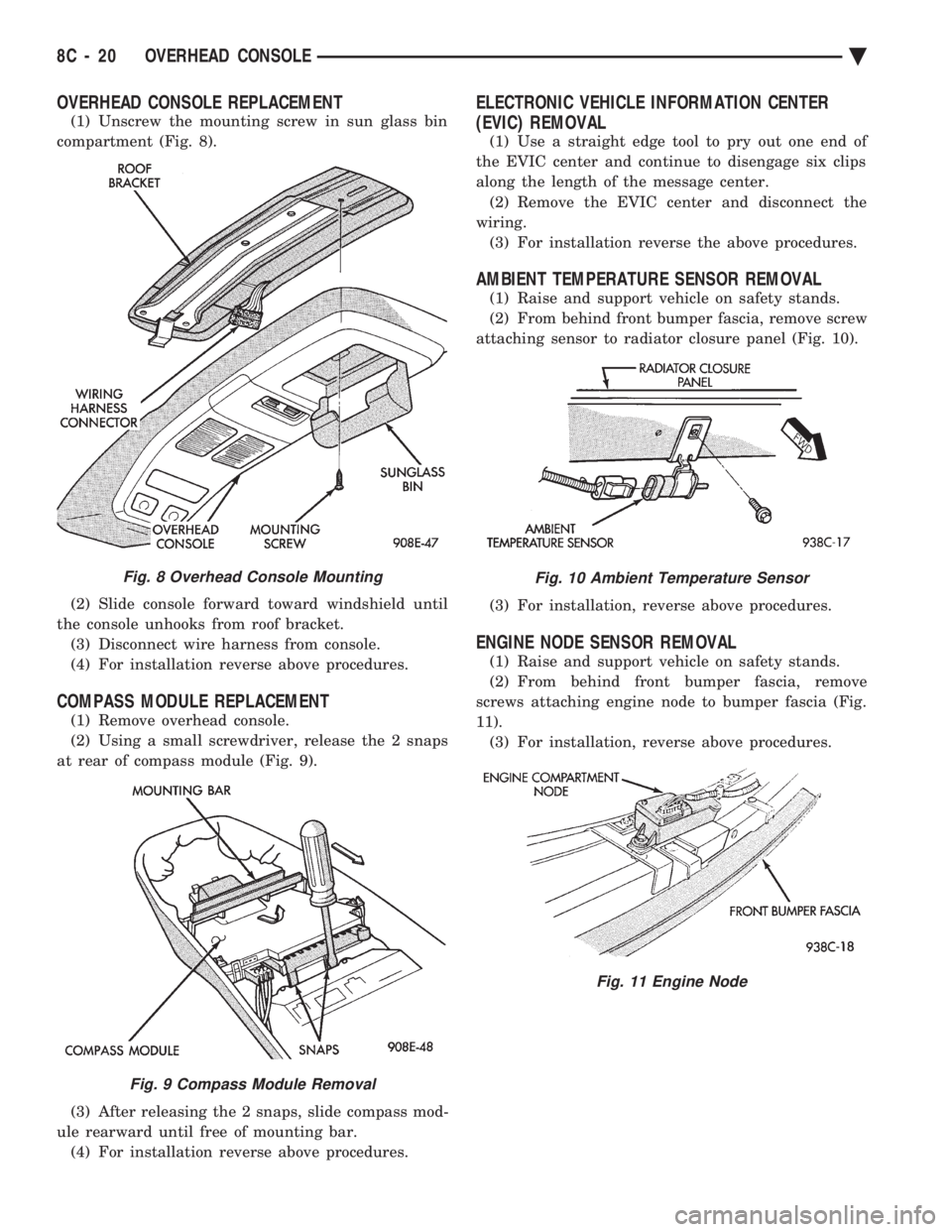
(1) Unscrew the mounting screw in sun glass bin
compartment (Fig. 8).
(2) Slide console forward toward windshield until
the console unhooks from roof bracket. (3) Disconnect wire harness from console.
(4) For installation reverse above procedures.
COMPASS MODULE REPLACEMENT
(1) Remove overhead console.
(2) Using a small screwdriver, release the 2 snaps
at rear of compass module (Fig. 9).
(3) After releasing the 2 snaps, slide compass mod-
ule rearward until free of mounting bar. (4) For installation reverse above procedures.
ELECTRONIC VEHICLE INFORMATION CENTER
(EVIC) REMOVAL
(1) Use a straight edge tool to pry out one end of
the EVIC center and continue to disengage six clips
along the length of the message center. (2) Remove the EVIC center and disconnect the
wiring. (3) For installation reverse the above procedures.
AMBIENT TEMPERATURE SENSOR REMOVAL
(1) Raise and support vehicle on safety stands.
(2) From behind front bumper fascia, remove screw
attaching sensor to radiator closure panel (Fig. 10).
(3) For installation, reverse above procedures.
ENGINE NODE SENSOR REMOVAL
(1) Raise and support vehicle on safety stands.
(2) From behind front bumper fascia, remove
screws attaching engine node to bumper fascia (Fig.
11). (3) For installation, reverse above procedures.
Fig. 8 Overhead Console Mounting
Fig. 9 Compass Module Removal
Fig. 10 Ambient Temperature Sensor
Fig. 11 Engine Node
8C - 20 OVERHEAD CONSOLE Ä
Page 438 of 2438
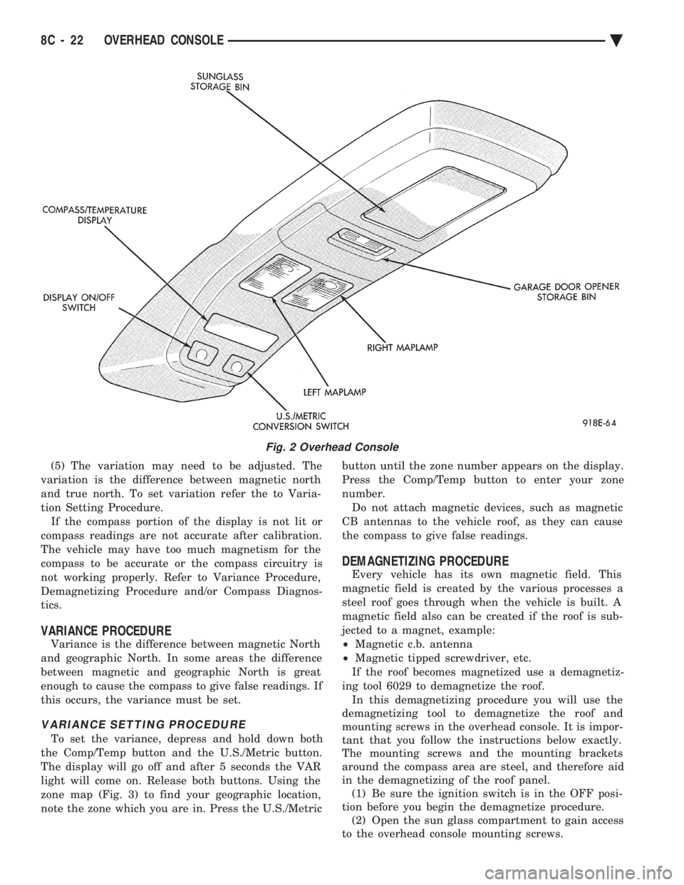
(5) The variation may need to be adjusted. The
variation is the difference between magnetic north
and true north. To set variation refer the to Varia-
tion Setting Procedure. If the compass portion of the display is not lit or
compass readings are not accurate after calibration.
The vehicle may have too much magnetism for the
compass to be accurate or the compass circuitry is
not working properly. Refer to Variance Procedure,
Demagnetizing Procedure and/or Compass Diagnos-
tics.
VARIANCE PROCEDURE
Variance is the difference between magnetic North
and geographic North. In some areas the difference
between magnetic and geographic North is great
enough to cause the compass to give false readings. If
this occurs, the variance must be set.
VARIANCE SETTING PROCEDURE
To set the variance, depress and hold down both
the Comp/Temp button and the U.S./Metric button.
The display will go off and after 5 seconds the VAR
light will come on. Release both buttons. Using the
zone map (Fig. 3) to find your geographic location,
note the zone which you are in. Press the U.S./Metric button until the zone number appears on the display.
Press the Comp/Temp button to enter your zone
number. Do not attach magnetic devices, such as magnetic
CB antennas to the vehicle roof, as they can cause
the compass to give false readings.
DEMAGNETIZING PROCEDURE
Every vehicle has its own magnetic field. This
magnetic field is created by the various processes a
steel roof goes through when the vehicle is built. A
magnetic field also can be created if the roof is sub-
jected to a magnet, example:
² Magnetic c.b. antenna
² Magnetic tipped screwdriver, etc.
If the roof becomes magnetized use a demagnetiz-
ing tool 6029 to demagnetize the roof. In this demagnetizing procedure you will use the
demagnetizing tool to demagnetize the roof and
mounting screws in the overhead console. It is impor-
tant that you follow the instructions below exactly.
The mounting screws and the mounting brackets
around the compass area are steel, and therefore aid
in the demagnetizing of the roof panel. (1) Be sure the ignition switch is in the OFF posi-
tion before you begin the demagnetize procedure. (2) Open the sun glass compartment to gain access
to the overhead console mounting screws.
Fig. 2 Overhead Console
8C - 22 OVERHEAD CONSOLE Ä
Page 441 of 2438

Test 3 (d3) performs a walking segment test which,
sequentially puts different directions and numbers on
the display. If any segment fails, replace the compass
module.
OVERHEAD CONSOLE REPLACEMENT
(1) Unscrew the mounting screw in sun glass bin
compartment (Fig. 6).
(2) Slide console forward toward windshield until
the console unhooks from roof bracket. (3) Disconnect wire harness from console.
(4) For installation reverse above procedures.
COMPASS MODULE REPLACEMENT
(1) Remove overhead console (Fig 6).
(2) Using a small screwdriver, release the 2 snaps
at rear of compass module (Fig. 7). (3) After releasing the 2 snaps, slide compass mod-
ule rearward until free of mounting bar. (4) For installation reverse above procedures.
AMBIENT TEMPERATURE SENSOR REMOVAL
(1) Raise and support vehicle on safety stands.
(2) Behind front bumper fascia, remove screw at-
taching sensor to radiator closure panel (Fig. 8). (3) For installation, reverse above procedures.
Fig. 6 Overhead Console Mounting
Fig. 7 Compass Module Removal
Fig. 8 Ambient Temperature Sensor
Ä
OVERHEAD CONSOLE 8C - 25
Page 1067 of 2438

Wiring Diagram
Name Sheet Number
Blower Slide Control .........................51
Illumination Lamp ...........................51
Resistor .................................51
Horn System ............................ .63, 64
Clockspring ...............................63
Horn (Hi-note) .............................63
Horn (Lo-note) .............................63
Horn Relay ...............................63
Horn Switch ..............................63
Idle Air Control Motor .................... .14, 21, 26
Ignition Switch .............................4,11
Injectors ............................ .15, 20, 24
Illuminated Entry System ........................91
Left Front Door Courtesy Lamp ..................91
Left Front Door Illuminated Entry Switch ............91
Right Front Door Courtesy Lamp .................91
Right Front Door Illuminated Entry Switch ...........91
Instrument Panel to Multi-Function Switch Wiring .......180
Instrument Panel Ground System ...................86
Interface Grommet ............................58
Intermittent Wiper System .................... .61, 62
Intermittent Wiper Motor ......................62
Intermittent Wiper Switch ......................61
Washer Pump Motor .........................61
Windshield Washer Low Fluid Level Sensor ...........61
Key Cylinders .......................... .131, 135
Key-In Switch .......................... .104, 107
Keyless Entry Connectors ...................... .208
Lamp Outage Module ...................... .96, 209
Lamps Ash Receiver Lamp ........................ .111
Back-Up Lamps ................ .161, 162, 163, 164
Center High Mounted Stop Lamp ......161, 162, 163, 164
Cornering Lamp Left ...............74, 77, 80, 82, 84
Cornering Lamp Right ..............73, 75, 78, 81, 83
Courtesy Lamps ................... .87, 88, 89, 90
Deck Lid Ajar Warning Lamp ....................95
Door Ajar Lamps ...........................95
Door Courtesy Lamp ................ .87, 88, 90, 91
Glove Box Lamp .......................... .111
Halo Lamp .......................... .104, 106
Headlamp-Left ............... .70, 72, 74, 80, 82, 84
Headlamp-Right ............ .69, 71, 73, 75, 78, 81, 83
Headlamp Switch Lamp .......................85
Illuminated Entry Lamps .......................91
Illumination Lamp ..................... .51, 53, 55
License Lamp .................. .161, 162, 163, 164
Low Engine Oil Pressure Lamp .............30, 31, 32
Low Windshield Washer Fluid Warning Lamp .........95
Parking/Turn Lamp-Left ........70, 72, 74, 77, 80, 82, 84
Parking/Turn Lamp-Right .......69, 71, 73, 75, 78, 81, 83
Park Lamp-Left ............................74
Park Lamp-Right ...........................73
Reading Lamps ............................90
Security Lamp ..................... .128, 132, 136
Side Marker Lamp-Left Front ............70, 72, 82, 84
Side Marker Lamp-Right Front ...........69, 71, 81, 83Wiring Diagram
Name Sheet Number
Side Marker Lamp-Left Rear ................161, 163
Side Marker Lamp-Right Rear ...............162, 164
Tail, Stop/Turn Signal Lamp-Left Rear ..........161, 163
Tail, Stop/Turn Signal Lamp-Right Rear .........162, 164
Transmission Range Lamp .....................85
Trunk Lamp ...............................90
Turn Signal Lamp-Left Front ...............74, 77, 80
Turn Signal Lamp-Right Front ..............73, 75, 78
Underhood Lamp ......................... .159
Vanity Mirror ..............................89
Visor Lamp ...............................89
Left Body to Instrument Panel Wiring ............190, 191
Left Front Door Jamb Switch .....................87
Left Rear Door Jamb Switch ......................87
MAP Sensor .......................... .18, 21, 26
Mechanical Cluster Printed Circuit Board .............167
Mechanical Cluster Printed Circuit Board Connectors ......166
Memory Power Seat & Mirror Connector .............204
Memory Power Seat System ...........151, 152, 153, 154
Circuit Breaker ........................... .153
Left Power Seat Motors ..................... .153
Left Power Seat Switch ...................... .152
Left Power Seat Switch Insulator ................152
Left Recliner Motor ........................ .154
Memory Module ................ .151, 152, 153, 154
Recliner Position Sense Resistor .................154
Recliner Seat Switch ....................... .152
Relay Bank ............................. .153
Seat Memory Selector Switch ...................151
Seat Track Position Sense Resistor ...............154
Memory Power Seat System Connectors .............205
Message Center Connector ..................... .207
Mirror-Heated ....................... .143, 144, 146
Mirror-Power .................... .143, 144, 145, 146
Modules Airbag System Diagnostic Module .................57
Air Suspension Control Module ................41, 43
ATC Power Module ........................ .115
Daytime Running Lamp Module ...........72, 76, 79, 84
Lamp Outage Module .................... .96, 209
Mirror Memory Module .................. .143, 144
Power Seat Memory Module .........151, 152, 153, 154
Powertrain Control Module ........14, 15, 16, 17, 18, 19,
20, 21, 22, 23, 24, 25, 26, 27, 28, 29, 37
Relay Module ............................ .171
Remote Keyless Entry Module ...............141, 142
Security Alarm Module ......127, 128, 129, 130, 131, 132,
133, 134, 135, 136, 137, 138
Sunroof Control .......................... .147
Transmission Control Module ...............33, 34, 35
Motors ABS Pump Motor ...........................46
Antenna Motor ........................... .118
Blower-A/C ............................ .53, 55
Blower ATC ............................. .115
Blower-Heater .............................51
Compressor Motor ....................... .40, 42
Ä WIRING DIAGRAMS AC-AY BODY 8W - 317