1993 CHEVROLET PLYMOUTH ACCLAIM roof rack
[x] Cancel search: roof rackPage 2162 of 2438
POWER SUNROOF INDEX
page page
Adjustment Bracket ........................ 7
Drain Channel ............................ 7
Drive Cable Locators ....................... 7
Drive Cables ............................. 8
General Information ........................ 6
Glass Panel ............................. 7 Glass Vertical Height Adjustment
.............. 6
Guide Assembly .......................... 8
Motor and Drive Gears ..................... 7
Sunshade ............................... 8
Wind Deflector ........................... 6
GENERAL INFORMATION
All sunroofs are equipped with drain tubes that are
located in the A, B or C-pillars. The drain tubes
must be kept open to prevent water from entering
the passenger compartment.
LUBRICATION
(1) Lubricate cables with Lubriplate or equivalent
when cables are replaced. (2) Periodically clean dirt from guide rail covers.
DRAIN TUBES
² Inspect the drain holes, located in the trough
around the sunroof opening to verify they are clear.
Inspection should be performed at least once a year
or when problems are suspected. If drain hose or
tubes are plugged, use compressed air or blunt flexi-
ble wire to clear them. If tubes cannot be cleared,
they must be repaired.
² The lower ends of the rear drain tubes are located
in the rear quarter panel drop wells. To clear rear
drain tubes, use compressed air or blunt flexible wire
from the lower ends of the tubes.
GLASS VERTICAL HEIGHT ADJUSTMENT
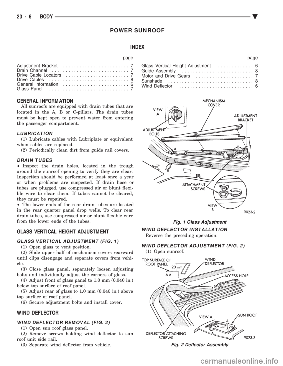
GLASS VERTICAL ADJUSTMENT (FIG. 1)
(1) Open glass to vent position.
(2) Slide upper half of mechanism covers rearward
until clips disengage and separate covers from vehi-
cle. (3) Close glass panel, separately loosen adjusting
bolts and individually adjust the corners of glass. (4) Adjust front of glass panel to 1.0 mm (0.040 in.)
below top surface of roof panel. (5) Adjust rear of glass to 1.0 mm (0.040 in.) above
top surface of roof panel. (6) Secure adjustment bolts and install cover.
WIND DEFLECTOR
WIND DEFLECTOR REMOVAL (FIG. 2)
(1) Open sun roof glass panel.
(2) Remove screws holding wind deflector to sun
roof unit side rail. (3) Separate wind deflector from vehicle.
WIND DEFLECTOR INSTALLATION
Reverse the preceding operation.
WIND DEFLECTOR ADJUSTMENT (FIG. 2)
(1) Open sunroof.
Fig. 1 Glass Adjustment
Fig. 2 Deflector Assembly
23 - 6 BODY Ä
Page 2163 of 2438
(2) position wind deflector so 19 mm (0.75 in.)
above top surface of roof panel and 1 mm (0.040 in.)
rearward of roof panel forward edge. (3) Secure wind deflector to sunroof unit.
GLASS PANEL
GLASS PANEL REMOVAL
(1) Remove wind deflector mechanism covers (Fig.
1). (2) Position glass to vent position.
(3) Position sunshade full rearward.
(4) Loosen nuts holding glass panel to side adjust-
ment brackets. (5) Slide glass panel rearward 12 mm (0.5 in.) and
separate glass from sunroof unit.
GLASS PANEL INSTALLATION
(1) Position glass panel in opening with logo rear-
ward and slide panel forward 12 mm (0.5 in.). (2) Verify that attaching nuts are below top sur-
face of glass adjustment brackets. (3) Close sunroof to center glass panel in roof open-
ing. (4) Tighten center screws to hold adjustment.
(5) Open glass to vent position and tighten nuts to
8N Im (70.8 in-lbs.).
(6) Close glass and check alignment.
(7) Install the mechanism covers.
(8) Adjust wind deflector, if necessary.
ADJUSTMENT BRACKET
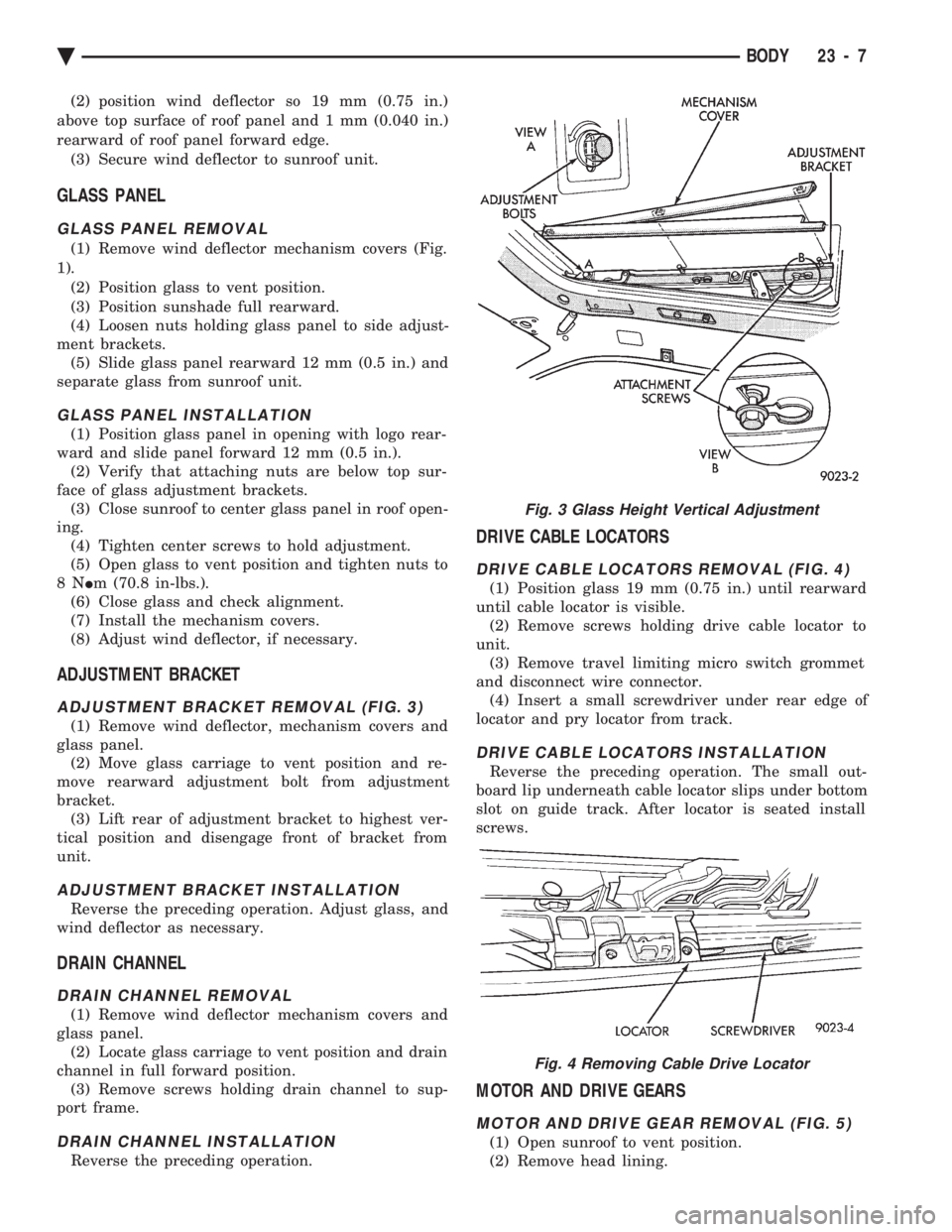
ADJUSTMENT BRACKET REMOVAL (FIG. 3)
(1) Remove wind deflector, mechanism covers and
glass panel. (2) Move glass carriage to vent position and re-
move rearward adjustment bolt from adjustment
bracket. (3) Lift rear of adjustment bracket to highest ver-
tical position and disengage front of bracket from
unit.
ADJUSTMENT BRACKET INSTALLATION
Reverse the preceding operation. Adjust glass, and
wind deflector as necessary.
DRAIN CHANNEL
DRAIN CHANNEL REMOVAL
(1) Remove wind deflector mechanism covers and
glass panel. (2) Locate glass carriage to vent position and drain
channel in full forward position. (3) Remove screws holding drain channel to sup-
port frame.
DRAIN CHANNEL INSTALLATION
Reverse the preceding operation.
DRIVE CABLE LOCATORS
DRIVE CABLE LOCATORS REMOVAL (FIG. 4)
(1) Position glass 19 mm (0.75 in.) until rearward
until cable locator is visible. (2) Remove screws holding drive cable locator to
unit. (3) Remove travel limiting micro switch grommet
and disconnect wire connector. (4) Insert a small screwdriver under rear edge of
locator and pry locator from track.
DRIVE CABLE LOCATORS INSTALLATION
Reverse the preceding operation. The small out-
board lip underneath cable locator slips under bottom
slot on guide track. After locator is seated install
screws.
MOTOR AND DRIVE GEARS
MOTOR AND DRIVE GEAR REMOVAL (FIG. 5)
(1) Open sunroof to vent position.
(2) Remove head lining.
Fig. 3 Glass Height Vertical Adjustment
Fig. 4 Removing Cable Drive Locator
Ä BODY 23 - 7
Page 2164 of 2438
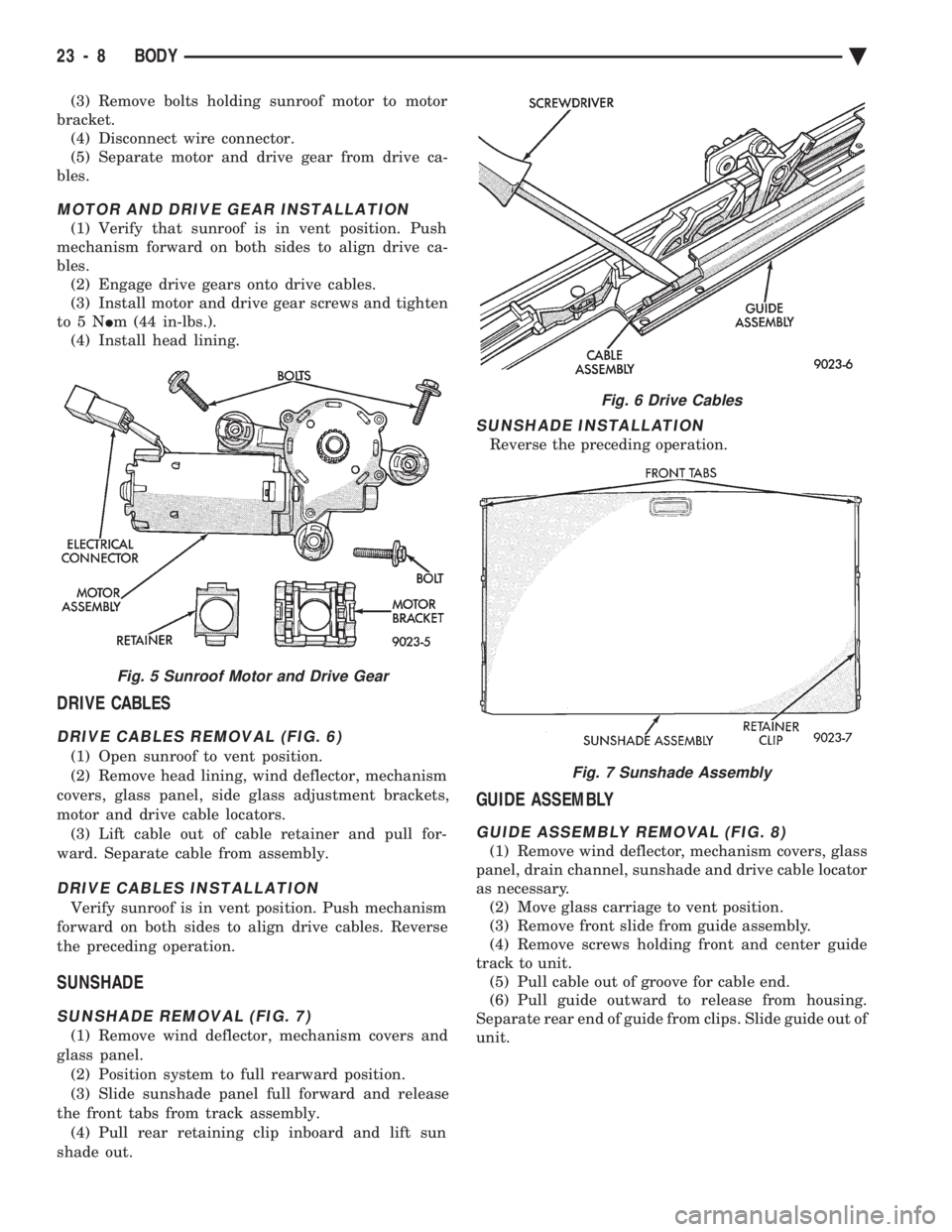
(3) Remove bolts holding sunroof motor to motor
bracket. (4) Disconnect wire connector.
(5) Separate motor and drive gear from drive ca-
bles.
MOTOR AND DRIVE GEAR INSTALLATION
(1) Verify that sunroof is in vent position. Push
mechanism forward on both sides to align drive ca-
bles. (2) Engage drive gears onto drive cables.
(3) Install motor and drive gear screws and tighten
to5N Im (44 in-lbs.).
(4) Install head lining.
DRIVE CABLES
DRIVE CABLES REMOVAL (FIG. 6)
(1) Open sunroof to vent position.
(2) Remove head lining, wind deflector, mechanism
covers, glass panel, side glass adjustment brackets,
motor and drive cable locators. (3) Lift cable out of cable retainer and pull for-
ward. Separate cable from assembly.
DRIVE CABLES INSTALLATION
Verify sunroof is in vent position. Push mechanism
forward on both sides to align drive cables. Reverse
the preceding operation.
SUNSHADE
SUNSHADE REMOVAL (FIG. 7)
(1) Remove wind deflector, mechanism covers and
glass panel. (2) Position system to full rearward position.
(3) Slide sunshade panel full forward and release
the front tabs from track assembly. (4) Pull rear retaining clip inboard and lift sun
shade out.
SUNSHADE INSTALLATION
Reverse the preceding operation.
GUIDE ASSEMBLY
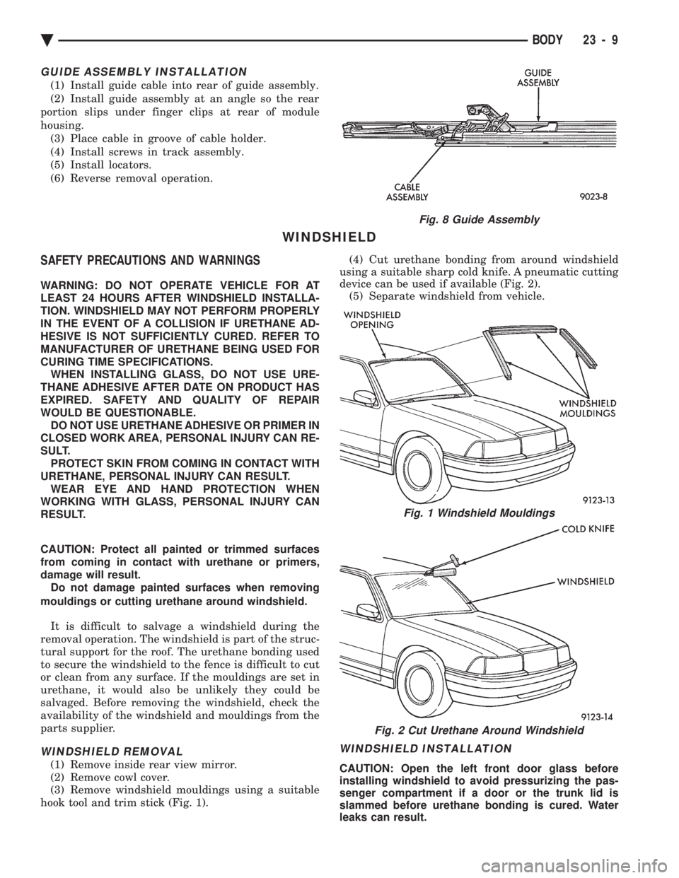
GUIDE ASSEMBLY REMOVAL (FIG. 8)
(1) Remove wind deflector, mechanism covers, glass
panel, drain channel, sunshade and drive cable locator
as necessary. (2) Move glass carriage to vent position.
(3) Remove front slide from guide assembly.
(4) Remove screws holding front and center guide
track to unit. (5) Pull cable out of groove for cable end.
(6) Pull guide outward to release from housing.
Separate rear end of guide from clips. Slide guide out of
unit.
Fig. 5 Sunroof Motor and Drive Gear
Fig. 6 Drive Cables
Fig. 7 Sunshade Assembly
23 - 8 BODY Ä
Page 2165 of 2438
GUIDE ASSEMBLY INSTALLATION
(1) Install guide cable into rear of guide assembly.
(2) Install guide assembly at an angle so the rear
portion slips under finger clips at rear of module
housing. (3) Place cable in groove of cable holder.
(4) Install screws in track assembly.
(5) Install locators.
(6) Reverse removal operation.
WINDSHIELD
SAFETY PRECAUTIONS AND WARNINGS
WARNING: DO NOT OPERATE VEHICLE FOR AT
LEAST 24 HOURS AFTER WINDSHIELD INSTALLA-
TION. WINDSHIELD MAY NOT PERFORM PROPERLY
IN THE EVENT OF A COLLISION IF URETHANE AD-
HESIVE IS NOT SUFFICIENTLY CURED. REFER TO
MANUFACTURER OF URETHANE BEING USED FOR
CURING TIME SPECIFICATIONS. WHEN INSTALLING GLASS, DO NOT USE URE-
THANE ADHESIVE AFTER DATE ON PRODUCT HAS
EXPIRED. SAFETY AND QUALITY OF REPAIR
WOULD BE QUESTIONABLE. DO NOT USE URETHANE ADHESIVE OR PRIMER IN
CLOSED WORK AREA, PERSONAL INJURY CAN RE-
SULT. PROTECT SKIN FROM COMING IN CONTACT WITH
URETHANE, PERSONAL INJURY CAN RESULT. WEAR EYE AND HAND PROTECTION WHEN
WORKING WITH GLASS, PERSONAL INJURY CAN
RESULT.
CAUTION: Protect all painted or trimmed surfaces
from coming in contact with urethane or primers,
damage will result. Do not damage painted surfaces when removing
mouldings or cutting urethane around windshield.
It is difficult to salvage a windshield during the
removal operation. The windshield is part of the struc-
tural support for the roof. The urethane bonding used
to secure the windshield to the fence is difficult to cut
or clean from any surface. If the mouldings are set in
urethane, it would also be unlikely they could be
salvaged. Before removing the windshield, check the
availability of the windshield and mouldings from the
parts supplier.
WINDSHIELD REMOVAL
(1) Remove inside rear view mirror.
(2) Remove cowl cover.
(3) Remove windshield mouldings using a suitable
hook tool and trim stick (Fig. 1). (4) Cut urethane bonding from around windshield
using a suitable sharp cold knife. A pneumatic cutting
device can be used if available (Fig. 2). (5) Separate windshield from vehicle.
WINDSHIELD INSTALLATION
CAUTION: Open the left front door glass before
installing windshield to avoid pressurizing the pas-
senger compartment if a door or the trunk lid is
slammed before urethane bonding is cured. Water
leaks can result.
Fig. 8 Guide Assembly
Fig. 1 Windshield Mouldings
Fig. 2 Cut Urethane Around Windshield
Ä BODY 23 - 9
Page 2167 of 2438
AA-VEHICLE BODY COMPONENT SERVICE INDEX
page page
A-Pillar and Roof Rail Mouldings ............. 25
B-Pillar Trim Panel ....................... 25
Body Side Moulding and Applique ............ 24
Cowl Cover ............................. 13
Cowl Panel Trim and Scuff Plates ............ 25
Door Opening Weatherstrips ................ 24
Floor Carpet ............................ 30
Front Center Console ..................... 29
Front Door and Hinge ..................... 15
Front Door Belt Moulding and Weatherstrip ..... 17
Front Door Glass ........................ 17
Front Door Glass Channel and Run Weatherstrip . 18
Front Door Glass Run Lower Channel ......... 18
Front Door Latch ......................... 16
Front Door Side View Mirror ................ 17
Front Door Silencer and Water Shield ......... 15
Front Door Trim Panel .................... 14
Front Door Window Regulator/Manual ......... 18
Front Door Window Regulator/Power .......... 19
Front End Splash Shields .................. 13
Front Fender ............................ 14
Front Power Door Lock Actuator ............. 19
Front Seat Belts ......................... 27
Front Seats ............................. 28
Fuel Fill Door ........................... 36
Grille .................................. 11
Head Lining ............................. 30
Hood and Hinges ........................ 11
Hood Latch and Release Cable .............. 12
Outside Front Door Latch Release Handle ..... 16
Outside Rear Door Latch Release Handle ...... 21 Overhead Console
........................ 30
Quarter Extension Trim Panel ............... 27
Quarter Trim Panel ....................... 27
Rear Deck Filler Panel .................... 31
Rear Door and Hinge ..................... 20
Rear Door Belt Moulding and Weatherstrip ..... 22
Rear Door Glass ......................... 22
Rear Door Glass Run Weatherstrip ........... 22
Rear Door Glass Stationary Glass Module ..... 23
Rear Door Latch ......................... 21
Rear Door Silencer and Water Shield ......... 20
Rear Door Trim Panel ..................... 20
Rear Door Window Regulator/Manual ......... 23
Rear Door Window Regulator/Power .......... 23
Rear Power Door Lock Actuator ............. 22
Rear Seat Belts .......................... 28
Rear Seats ............................. 28
Rear Shelf Trim Panel ..................... 27
Rear Window Glass ...................... 32
Sun Roof Air Deflector .................... 31
Sun Roof Drain Tubes .................... 31
Sun Roof Weatherstrip .................... 31
Trunk Lid .............................. 33
Trunk Lid Hinge ......................... 34
Trunk Lid Latch .......................... 34
Trunk Lid Lock .......................... 34
Trunk Lid Luggage Rack ................... 35
Trunk Lid Torsion Bar ..................... 34
Trunk Lining ............................ 35
Trunk Opening Weatherstrip ................ 35
Vinyl Roof Bonnet ........................ 31
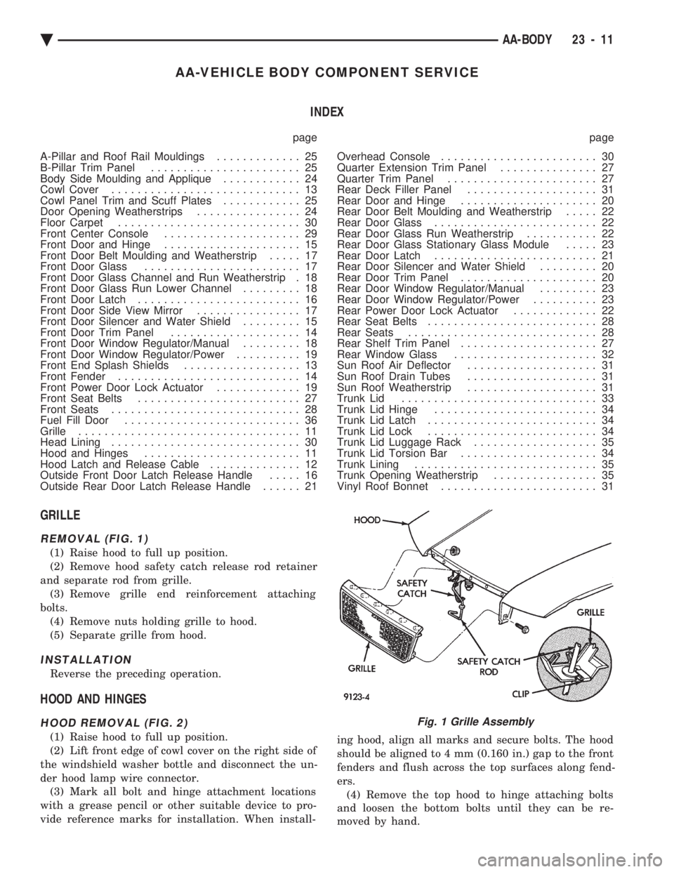
GRILLE
REMOVAL (FIG. 1)
(1) Raise hood to full up position.
(2) Remove hood safety catch release rod retainer
and separate rod from grille. (3) Remove grille end reinforcement attaching
bolts. (4) Remove nuts holding grille to hood.
(5) Separate grille from hood.
INSTALLATION
Reverse the preceding operation.
HOOD AND HINGES
HOOD REMOVAL (FIG. 2)
(1) Raise hood to full up position.
(2) Lift front edge of cowl cover on the right side of
the windshield washer bottle and disconnect the un-
der hood lamp wire connector. (3) Mark all bolt and hinge attachment locations
with a grease pencil or other suitable device to pro-
vide reference marks for installation. When install- ing hood, align all marks and secure bolts. The hood
should be aligned to 4 mm (0.160 in.) gap to the front
fenders and flush across the top surfaces along fend-
ers. (4) Remove the top hood to hinge attaching bolts
and loosen the bottom bolts until they can be re-
moved by hand.
Fig. 1 Grille Assembly
Ä AA-BODY 23 - 11
Page 2186 of 2438
INSTALLATION
Reverse the preceding operation. On vehicles with
automatic transaxle, verify gear selector indicator
adjustment before returning vehicle to use.
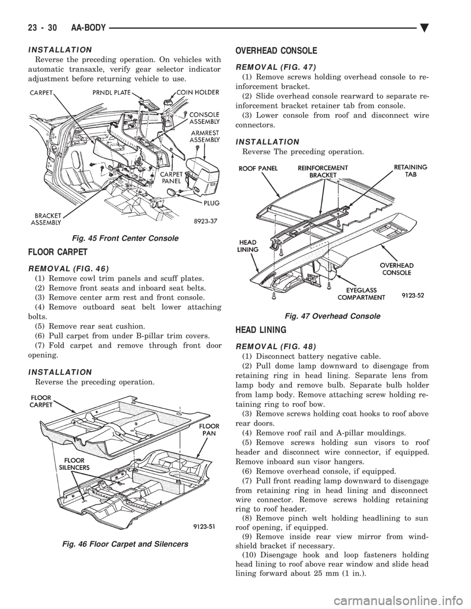
FLOOR CARPET
REMOVAL (FIG. 46)
(1) Remove cowl trim panels and scuff plates.
(2) Remove front seats and inboard seat belts.
(3) Remove center arm rest and front console.
(4) Remove outboard seat belt lower attaching
bolts. (5) Remove rear seat cushion.
(6) Pull carpet from under B-pillar trim covers.
(7) Fold carpet and remove through front door
opening.
INSTALLATION
Reverse the preceding operation.
OVERHEAD CONSOLE
REMOVAL (FIG. 47)
(1) Remove screws holding overhead console to re-
inforcement bracket. (2) Slide overhead console rearward to separate re-
inforcement bracket retainer tab from console. (3) Lower console from roof and disconnect wire
connectors.
INSTALLATION
Reverse The preceding operation.
HEAD LINING
REMOVAL (FIG. 48)
(1) Disconnect battery negative cable.
(2) Pull dome lamp downward to disengage from
retaining ring in head lining. Separate lens from
lamp body and remove bulb. Separate bulb holder
from lamp body. Remove attaching screw holding re-
taining ring to roof bow. (3) Remove screws holding coat hooks to roof above
rear doors. (4) Remove roof rail and A-pillar mouldings.
(5) Remove screws holding sun visors to roof
header and disconnect wire connector, if equipped.
Remove inboard sun visor hangers. (6) Remove overhead console, if equipped.
(7) Pull front reading lamp downward to disengage
from retaining ring in head lining and disconnect
wire connector. Remove screws holding retaining
ring to roof header. (8) Remove pinch welt holding headlining to sun
roof opening, if equipped. (9) Remove inside rear view mirror from wind-
shield bracket if necessary. (10) Disengage hook and loop fasteners holding
head lining to roof above rear window and slide head
lining forward about 25 mm (1 in.).
Fig. 45 Front Center Console
Fig. 46 Floor Carpet and Silencers
Fig. 47 Overhead Console
23 - 30 AA-BODY Ä
Page 2201 of 2438
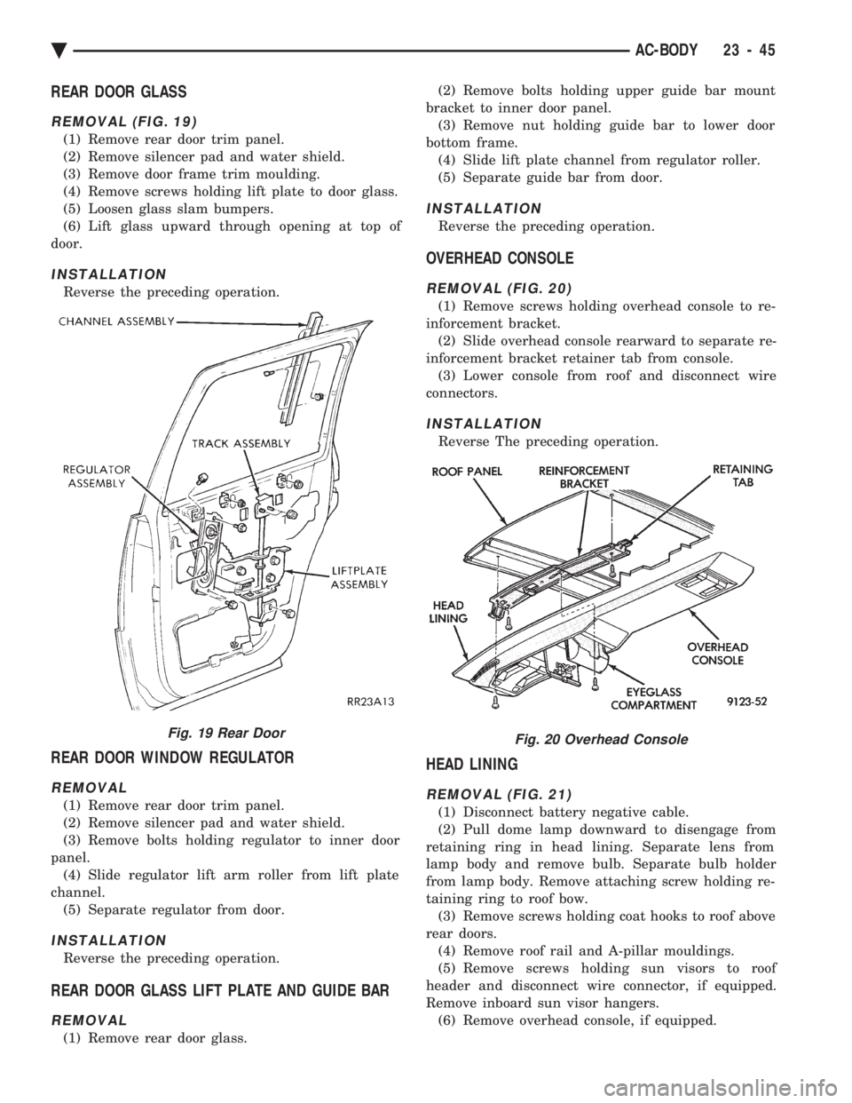
REAR DOOR GLASS
REMOVAL (FIG. 19)
(1) Remove rear door trim panel.
(2) Remove silencer pad and water shield.
(3) Remove door frame trim moulding.
(4) Remove screws holding lift plate to door glass.
(5) Loosen glass slam bumpers.
(6) Lift glass upward through opening at top of
door.
INSTALLATION
Reverse the preceding operation.
REAR DOOR WINDOW REGULATOR
REMOVAL
(1) Remove rear door trim panel.
(2) Remove silencer pad and water shield.
(3) Remove bolts holding regulator to inner door
panel. (4) Slide regulator lift arm roller from lift plate
channel. (5) Separate regulator from door.
INSTALLATION
Reverse the preceding operation.
REAR DOOR GLASS LIFT PLATE AND GUIDE BAR
REMOVAL
(1) Remove rear door glass. (2) Remove bolts holding upper guide bar mount
bracket to inner door panel. (3) Remove nut holding guide bar to lower door
bottom frame. (4) Slide lift plate channel from regulator roller.
(5) Separate guide bar from door.
INSTALLATION
Reverse the preceding operation.
OVERHEAD CONSOLE
REMOVAL (FIG. 20)
(1) Remove screws holding overhead console to re-
inforcement bracket. (2) Slide overhead console rearward to separate re-
inforcement bracket retainer tab from console. (3) Lower console from roof and disconnect wire
connectors.
INSTALLATION
Reverse The preceding operation.
HEAD LINING
REMOVAL (FIG. 21)
(1) Disconnect battery negative cable.
(2) Pull dome lamp downward to disengage from
retaining ring in head lining. Separate lens from
lamp body and remove bulb. Separate bulb holder
from lamp body. Remove attaching screw holding re-
taining ring to roof bow. (3) Remove screws holding coat hooks to roof above
rear doors. (4) Remove roof rail and A-pillar mouldings.
(5) Remove screws holding sun visors to roof
header and disconnect wire connector, if equipped.
Remove inboard sun visor hangers. (6) Remove overhead console, if equipped.
Fig. 19 Rear DoorFig. 20 Overhead Console
Ä AC-BODY 23 - 45
Page 2202 of 2438
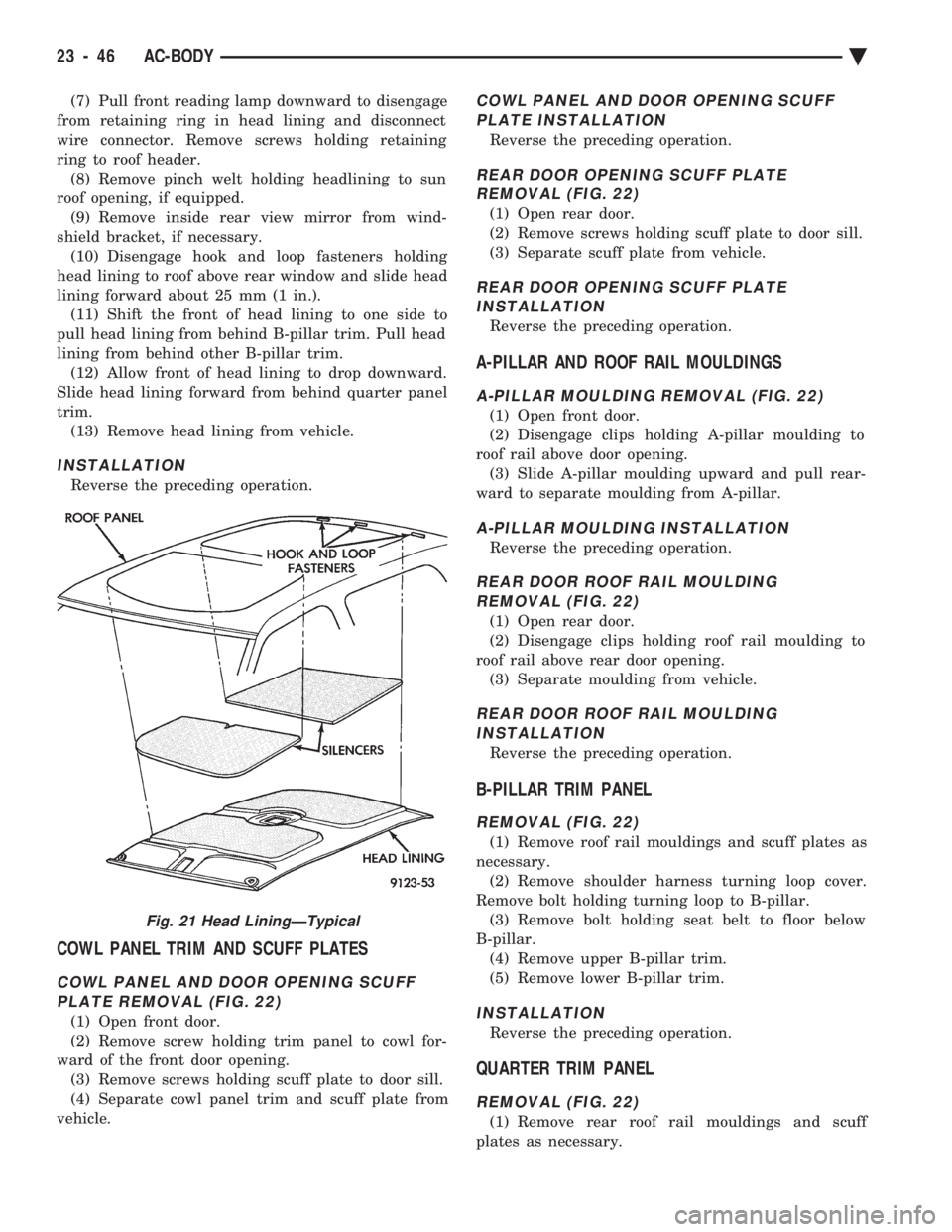
(7) Pull front reading lamp downward to disengage
from retaining ring in head lining and disconnect
wire connector. Remove screws holding retaining
ring to roof header. (8) Remove pinch welt holding headlining to sun
roof opening, if equipped. (9) Remove inside rear view mirror from wind-
shield bracket, if necessary. (10) Disengage hook and loop fasteners holding
head lining to roof above rear window and slide head
lining forward about 25 mm (1 in.). (11) Shift the front of head lining to one side to
pull head lining from behind B-pillar trim. Pull head
lining from behind other B-pillar trim. (12) Allow front of head lining to drop downward.
Slide head lining forward from behind quarter panel
trim. (13) Remove head lining from vehicle.
INSTALLATION
Reverse the preceding operation.
COWL PANEL TRIM AND SCUFF PLATES
COWL PANEL AND DOOR OPENING SCUFFPLATE REMOVAL (FIG. 22)
(1) Open front door.
(2) Remove screw holding trim panel to cowl for-
ward of the front door opening. (3) Remove screws holding scuff plate to door sill.
(4) Separate cowl panel trim and scuff plate from
vehicle.
COWL PANEL AND DOOR OPENING SCUFF PLATE INSTALLATION
Reverse the preceding operation.
REAR DOOR OPENING SCUFF PLATEREMOVAL (FIG. 22)
(1) Open rear door.
(2) Remove screws holding scuff plate to door sill.
(3) Separate scuff plate from vehicle.
REAR DOOR OPENING SCUFF PLATE INSTALLATION
Reverse the preceding operation.
A-PILLAR AND ROOF RAIL MOULDINGS
A-PILLAR MOULDING REMOVAL (FIG. 22)
(1) Open front door.
(2) Disengage clips holding A-pillar moulding to
roof rail above door opening. (3) Slide A-pillar moulding upward and pull rear-
ward to separate moulding from A-pillar.
A-PILLAR MOULDING INSTALLATION
Reverse the preceding operation.
REAR DOOR ROOF RAIL MOULDING REMOVAL (FIG. 22)
(1) Open rear door.
(2) Disengage clips holding roof rail moulding to
roof rail above rear door opening. (3) Separate moulding from vehicle.
REAR DOOR ROOF RAIL MOULDINGINSTALLATION
Reverse the preceding operation.
B-PILLAR TRIM PANEL
REMOVAL (FIG. 22)
(1) Remove roof rail mouldings and scuff plates as
necessary. (2) Remove shoulder harness turning loop cover.
Remove bolt holding turning loop to B-pillar. (3) Remove bolt holding seat belt to floor below
B-pillar. (4) Remove upper B-pillar trim.
(5) Remove lower B-pillar trim.
INSTALLATION
Reverse the preceding operation.
QUARTER TRIM PANEL
REMOVAL (FIG. 22)
(1) Remove rear roof rail mouldings and scuff
plates as necessary.
Fig. 21 Head LiningÐTypical
23 - 46 AC-BODY Ä