1993 CHEVROLET PLYMOUTH ACCLAIM refrigerant type
[x] Cancel search: refrigerant typePage 2305 of 2438
HEATING AND AIR CONDITIONING
CONTENTS
page page
AUTOMATIC TEMPERATURE CONTROL (ATC) .............................. 66
COMPONENT SERVICE PROCEDURES ...... 47
FIXED DISPLACEMENT COMPRESSORÐ MODEL 10PA17 ...................... 24
FIXED DISPLACEMENT COMPRESSORÐ MODEL SD709P ...................... 38 FIXED DISPLACEMENT COMPRESSORÐ
MODEL TR105 ....................... 32
GENERAL INFORMATION .................. 1
HEATER AND A/C PERFORMANCE TESTS .... 6
REFRIGERANT SERVICE PROCEDURES ...... 8
VACUUM CONTROL SYSTEM DIAGNOSIS .... 4
VARIABLE DISPLACEMENT COMPRESSORÐ MODEL 6C17 ......................... 13
GENERAL INFORMATION INDEX
page page
A/C System Identification ................... 1
Cooling System Precautions ................. 3
Description and Operation ................... 1
Engine Cooling System Requirements .......... 2 Handling Tubing and Fittings
................. 3
Safety Precautions and Warnings ............. 3
Side Window Demisters .................... 2
System Airflow ........................... 1
A/C SYSTEM IDENTIFICATION
The terms Fixed Displacement Compressor and
Variable Displacement Compressor will be used to
describe the two types of A/C systems used through-
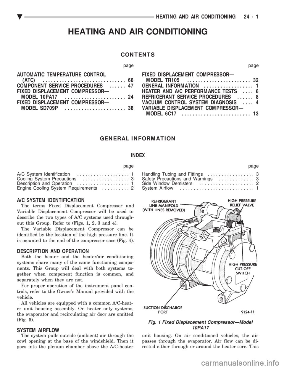
out this Group. Refer to (Figs. 1, 2, 3 and 4). The Variable Displacement Compressor can be
identified by the location of the high pressure line. It
is mounted to the end of the compressor case (Fig. 4).
DESCRIPTION AND OPERATION
Both the heater and the heater/air conditioning
systems share many of the same functioning compo-
nents. This Group will deal with both systems to-
gether when component function is common, and
separately when they are not. For proper operation of the instrument panel con-
trols, refer to the Owner's Manual provided with the
vehicle. All vehicles are equipped with a common A/C-heat-
er unit housing assembly. On heater only systems,
the evaporator and recirculating air door are omitted
(Fig. 5).
SYSTEM AIRFLOW
The system pulls outside (ambient) air through the
cowl opening at the base of the windshield. Then it
goes into the plenum chamber above the A/C-heater unit housing. On air conditioned vehicles, the air
passes through the evaporator. Air flow can be di-
rected either through or around the heater core. This
Fig. 1 Fixed Displacement CompressorÐModel 10PA17
Ä HEATING AND AIR CONDITIONING 24 - 1
Page 2307 of 2438
SAFETY PRECAUTIONS AND WARNINGS
WARNING: WEAR EYE PROTECTION WHEN SER-
VICING THE AIR CONDITIONING REFRIGERANT
SYSTEM. SERIOUS EYE INJURY CAN RESULT
FROM EYE CONTACT WITH REFRIGERANT. IF EYE
CONTACT IS MADE, SEEK MEDICAL ATTENTION
IMMEDIATELY. DO NOT EXPOSE REFRIGERANT TO OPEN
FLAME. POISONOUS GAS IS CREATED WHEN RE-
FRIGERANT IS BURNED. AN ELECTRONIC TYPE
LEAK DETECTOR IS RECOMMENDED. LARGE AMOUNTS OF REFRIGERANT RELEASED
IN A CLOSED WORK AREA WILL DISPLACE THE
OXYGEN AND CAUSE SUFFOCATION. THE EVAPORATION RATE OF (R-12) REFRIGER-
ANT AT AVERAGE TEMPERATURE AND ALTITUDE
IS EXTREMELY HIGH. AS A RESULT, ANYTHING
THAT COMES IN CONTACT WITH THE REFRIGER-
ANT WILL FREEZE. ALWAYS PROTECT SKIN OR
DELICATE OBJECTS FROM DIRECT CONTACT
WITH REFRIGERANT.
CAUTION: Liquid refrigerant is corrosive to metal
surfaces. Follow the operating instructions supplied
with equipment being used.
COOLING SYSTEM PRECAUTIONS
WARNING: ANTIFREEZE IS AN ETHYLENE GLYCOL
BASE COOLANT AND IS HARMFUL IF SWAL-
LOWED OR INHALED. IF SWALLOWED, DRINK
TWO GLASSES OF WATER AND INDUCE VOMIT-
ING. IF INHALED, MOVE TO FRESH AIR AREA.
SEEK MEDICAL ATTENTION IMMEDIATELY. DO NOT STORE IN OPEN OR UNMARKED CON-
TAINERS. WASH SKIN AND CLOTHING THOROUGHLY AF-
TER COMING IN CONTACT WITH ETHYLENE GLY-
COL. KEEP OUT OF REACH OF CHILDREN AND PETS.
DO NOT OPEN A COOLING SYSTEM WHEN THE
ENGINE IS AT RUNNING TEMPERATURE. PER-
SONAL INJURY CAN RESULT.
The engine cooling system is designed to develop
internal pressure of 97 to 123 kPa (14 to 18 psi). Al-
low the vehicle 15 minutes (or until a safe tempera-
ture and pressure are attained) before opening the
cooling system. Refer to Group 7, Cooling System.
HANDLING TUBING AND FITTINGS
Kinks in the refrigerant tubing or sharp bends in
the refrigerant hose lines will greatly reduce the ca-
pacity of the entire system. High pressures are pro-
duced in the system when it is operating. Extreme
care must be exercised to make sure that all connec-
tions are pressure tight. Dirt and moisture can enter
the system when it is opened for repair or replace-
ment of lines or components. The refrigerant oil will
absorb moisture readily out of the air. This moisture
will convert into acids within a closed system. The following precautions must be observed:
The system must be completely empty before open-
ing any fitting or connection in the refrigeration sys-
tem. Open fittings with caution even after the
system has been emptied. If any pressure is noticed
as a fitting is loosened, allow trapped pressure to
bleed off very slowly. A good rule for the flexible hose lines is to keep the
radius of all bends at least 10 times the diameter of
the hose. Sharper bends will reduce the flow of re-
frigerant. The flexible hose lines should be routed so
they are at least 3 inches (80 mm) from the exhaust
manifold. Inspect all flexible hose lines to make sure
they are in good condition and properly routed. Unified plumbing connections with aluminum gas-
kets cannot be serviced with O-rings. These gaskets
are not reusable and do not require lubrication be-
fore installing. The use of correct wrenches when making connec-
tions is very important. Improper wrenches or im-
proper use of wrenches can damage the fittings. The A/C system will remain chemical stabile as
long as pure-moisture-free R-12 and refrigerant oil is
used. Abnormal amounts of dirt, moisture or air can
upset the chemical stability. This condition could
cause operational troubles or even serious damage if
present in more than very small quantities. When it is necessary to open the refrigeration sys-
tem, have everything needed to service the system
ready. The system should not be left open any longer
than necessary. Cap or plug all lines and fittings as
soon as they are opened to prevent the entrance or
dirt and moisture. All lines and components in parts
stock should be capped or sealed until they are ready
to be used. All tools, including the refrigerant dispensing man-
ifold, the manifold gauge set, and test hoses should
be kept clean and dry.
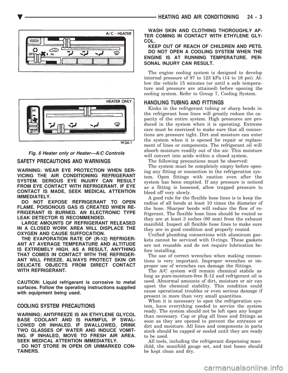
Fig. 6 Heater only or HeaterÐA/C Controls
Ä HEATING AND AIR CONDITIONING 24 - 3
Page 2312 of 2438
REFRIGERANT SERVICE PROCEDURES INDEX
page page
Adding Partial Refrigerant Charge ............ 10
Charging Refrigerant SystemÐEmpty System . . . 11
Discharging Refrigerant System .............. 11
Evacuating Refrigerant System .............. 11
Manifold Gauge Set Connections ............. 9 Oil Level
............................... 12
R-12 Refrigerant Equipment ................. 8
Refrigerant Recycling ...................... 9
Sight Glass Refrigerant Level Inspection ........ 8
Testing for Refrigerant Leaks ............... 10
SIGHT GLASS REFRIGERANT LEVEL INSPECTION
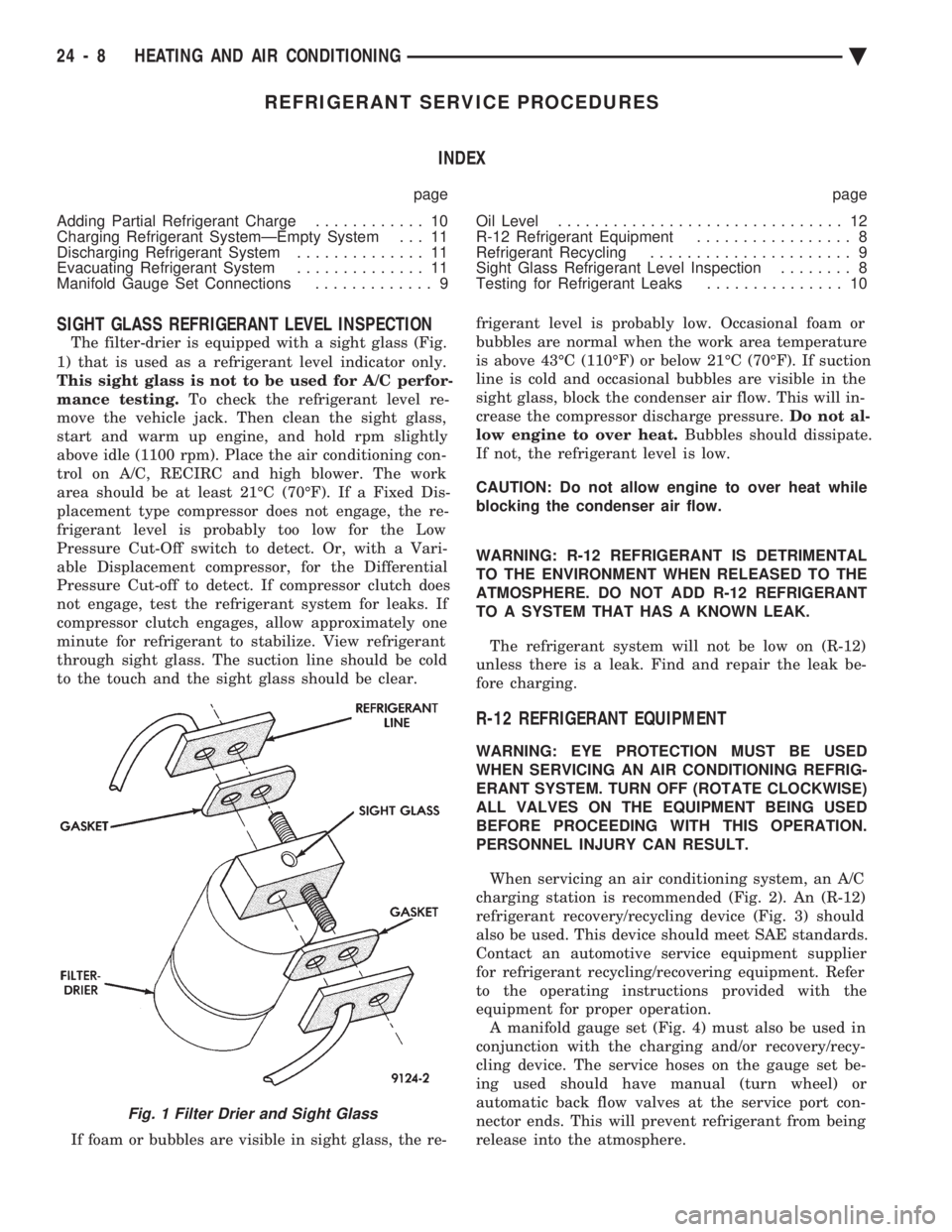
The filter-drier is equipped with a sight glass (Fig.
1) that is used as a refrigerant level indicator only.
This sight glass is not to be used for A/C perfor-
mance testing. To check the refrigerant level re-
move the vehicle jack. Then clean the sight glass,
start and warm up engine, and hold rpm slightly
above idle (1100 rpm). Place the air conditioning con-
trol on A/C, RECIRC and high blower. The work
area should be at least 21ÉC (70ÉF). If a Fixed Dis-
placement type compressor does not engage, the re-
frigerant level is probably too low for the Low
Pressure Cut-Off switch to detect. Or, with a Vari-
able Displacement compressor, for the Differential
Pressure Cut-off to detect. If compressor clutch does
not engage, test the refrigerant system for leaks. If
compressor clutch engages, allow approximately one
minute for refrigerant to stabilize. View refrigerant
through sight glass. The suction line should be cold
to the touch and the sight glass should be clear.
If foam or bubbles are visible in sight glass, the re- frigerant level is probably low. Occasional foam or
bubbles are normal when the work area temperature
is above 43ÉC (110ÉF) or below 21ÉC (70ÉF). If suction
line is cold and occasional bubbles are visible in the
sight glass, block the condenser air flow. This will in-
crease the compressor discharge pressure. Do not al-
low engine to over heat. Bubbles should dissipate.
If not, the refrigerant level is low.
CAUTION: Do not allow engine to over heat while
blocking the condenser air flow.
WARNING: R-12 REFRIGERANT IS DETRIMENTAL
TO THE ENVIRONMENT WHEN RELEASED TO THE
ATMOSPHERE. DO NOT ADD R-12 REFRIGERANT
TO A SYSTEM THAT HAS A KNOWN LEAK.
The refrigerant system will not be low on (R-12)
unless there is a leak. Find and repair the leak be-
fore charging.
R-12 REFRIGERANT EQUIPMENT
WARNING: EYE PROTECTION MUST BE USED
WHEN SERVICING AN AIR CONDITIONING REFRIG-
ERANT SYSTEM. TURN OFF (ROTATE CLOCKWISE)
ALL VALVES ON THE EQUIPMENT BEING USED
BEFORE PROCEEDING WITH THIS OPERATION.
PERSONNEL INJURY CAN RESULT.
When servicing an air conditioning system, an A/C
charging station is recommended (Fig. 2). An (R-12)
refrigerant recovery/recycling device (Fig. 3) should
also be used. This device should meet SAE standards.
Contact an automotive service equipment supplier
for refrigerant recycling/recovering equipment. Refer
to the operating instructions provided with the
equipment for proper operation. A manifold gauge set (Fig. 4) must also be used in
conjunction with the charging and/or recovery/recy-
cling device. The service hoses on the gauge set be-
ing used should have manual (turn wheel) or
automatic back flow valves at the service port con-
nector ends. This will prevent refrigerant from being
release into the atmosphere.
Fig. 1 Filter Drier and Sight Glass
24 - 8 HEATING AND AIR CONDITIONING Ä
Page 2316 of 2438
WARNING: REVIEW SAFETY PRECAUTIONS AND
WARNINGS BEFORE CHARGING THE REFRIGER-
ANT SYSTEM.
After the system has been tested for leaks and
evacuated, a refrigerant charge can be injected into
the system. (1) Connect manifold gauge set.
(2) Measure refrigerant (refer to capacities) and
heat to 52ÉC (125ÉF) with the charging station. Refer
to the instructions provided with the equipment be-
ing used.
REFRIGERANT CAPACITIES:
² Without Rear A/C = 907 g (32 oz.)
² With Rear A/C = 1219 g (43 oz.)
(3) Open the suction and discharge valves. Open
the charge valve to allow the heated refrigerant to
flow into the system. When the transfer of refriger-
ant has stopped, close the suction and discharge
valve. (4) If all of the refrigerant charge did not transfer
from the dispensing device, start engine and hold at
idle (1400 rpm). Set the A/C control to A/C, low
blower speed, and open windows. If the A/C compres-
sor does not engage, test the compressor clutch con-
trol circuit and correct any failure. Refer to Group
8W, Wiring Diagrams. (5) Open the suction valve to allow the remaining
refrigerant to transfer to the system.
WARNING: TAKE CARE NOT TO OPEN THE DIS-
CHARGE (HIGH-PRESSURE) VALVE AT THIS TIME.
(6) Close all valves and test the A/C system perfor-
mance. Refer to Heater and A/C Performance Tests
in this Group. (7) Disconnect the charging station or manifold
gauge set. Install the service port caps.
OIL LEVEL
It is important to have the correct amount of oil in
the A/C system to ensure proper lubrication of the
compressor. Too little oil will result in damage to the
compressor. Too much oil will reduce the cooling ca-
pacity of the system. The oil used in the compressor is a 500 SUS viscos-
ity, wax-free refrigerant oil. Only refrigerant oil of
the same type should be used to service the system.
Do not use any other oil. The oil container should be
kept tightly capped until it is ready for use, and then
tightly capped after use to prevent contamination
from dirt and moisture. Refrigerant oil will quickly
absorb any moisture it comes in contact with. It will not be necessary to check oil level in the
compressor or to add oil unless there has been an oil
loss. This may be due to a ruptured line, shaft seal leakage, leakage from the evaporator, condenser
leak, filter drier or loss of refrigerant due to a colli-
sion. Oil loss at a the leak point will be evident by
the presence of a wet, shiny surface around the leak.
REFRIGERANT OIL LEVEL CHECK
When an A/C system is assembled at the factory,
all components (except the compressor) are refriger-
ant oil free. After the system has been charged with
R-12 and operated, the oil in the compressor is dis-
persed through the lines and components. The evap-
orator, condenser, and filter-drier will retain a
significant amount of oil. (Refer to the Refrigerant
Oil Capacities chart). When a component is replaced,
the specified amount of refrigerant oil must be
added. When the compressor is replaced, the amount
of oil that is retained in the rest of the system must
be drained from the replacement compressor. When a
refrigerant line or component has ruptured and it
has released an unknown amount of oil. The A/C
compressor should be removed and drained through
the suction port. The filter-drier must be replaced
along with the ruptured part. Then the oil capacity
of the system (minus the amount of oil still in the re-
maining components) can be poured into the suction
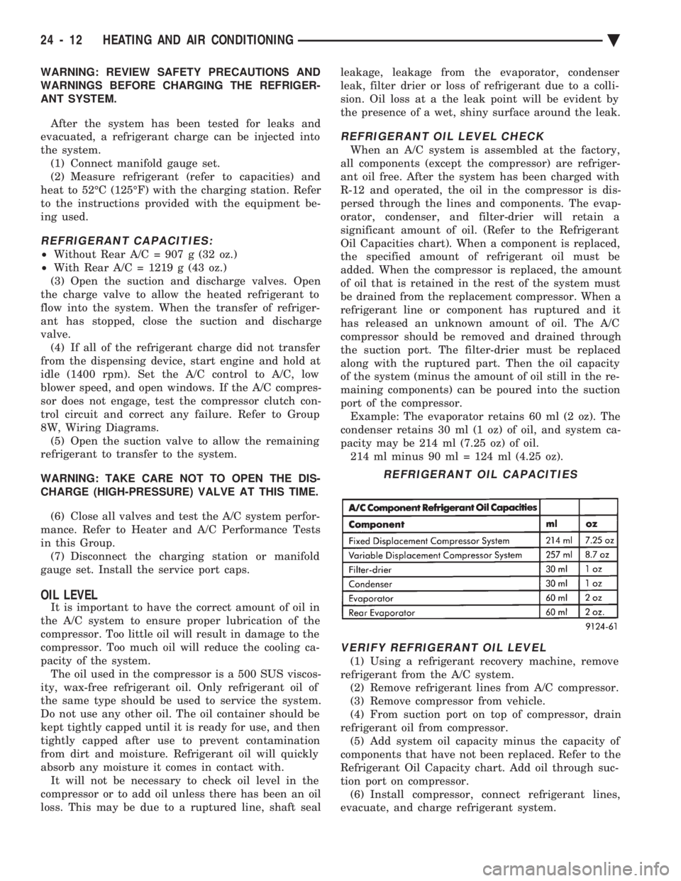
port of the compressor. Example: The evaporator retains 60 ml (2 oz). The
condenser retains 30 ml (1 oz) of oil, and system ca-
pacity may be 214 ml (7.25 oz) of oil. 214 ml minus 90 ml = 124 ml (4.25 oz).
VERIFY REFRIGERANT OIL LEVEL
(1) Using a refrigerant recovery machine, remove
refrigerant from the A/C system. (2) Remove refrigerant lines from A/C compressor.
(3) Remove compressor from vehicle.
(4) From suction port on top of compressor, drain
refrigerant oil from compressor. (5) Add system oil capacity minus the capacity of
components that have not been replaced. Refer to the
Refrigerant Oil Capacity chart. Add oil through suc-
tion port on compressor. (6) Install compressor, connect refrigerant lines,
evacuate, and charge refrigerant system.
REFRIGERANT OIL CAPACITIES
24 - 12 HEATING AND AIR CONDITIONING Ä
Page 2330 of 2438
REMOVAL
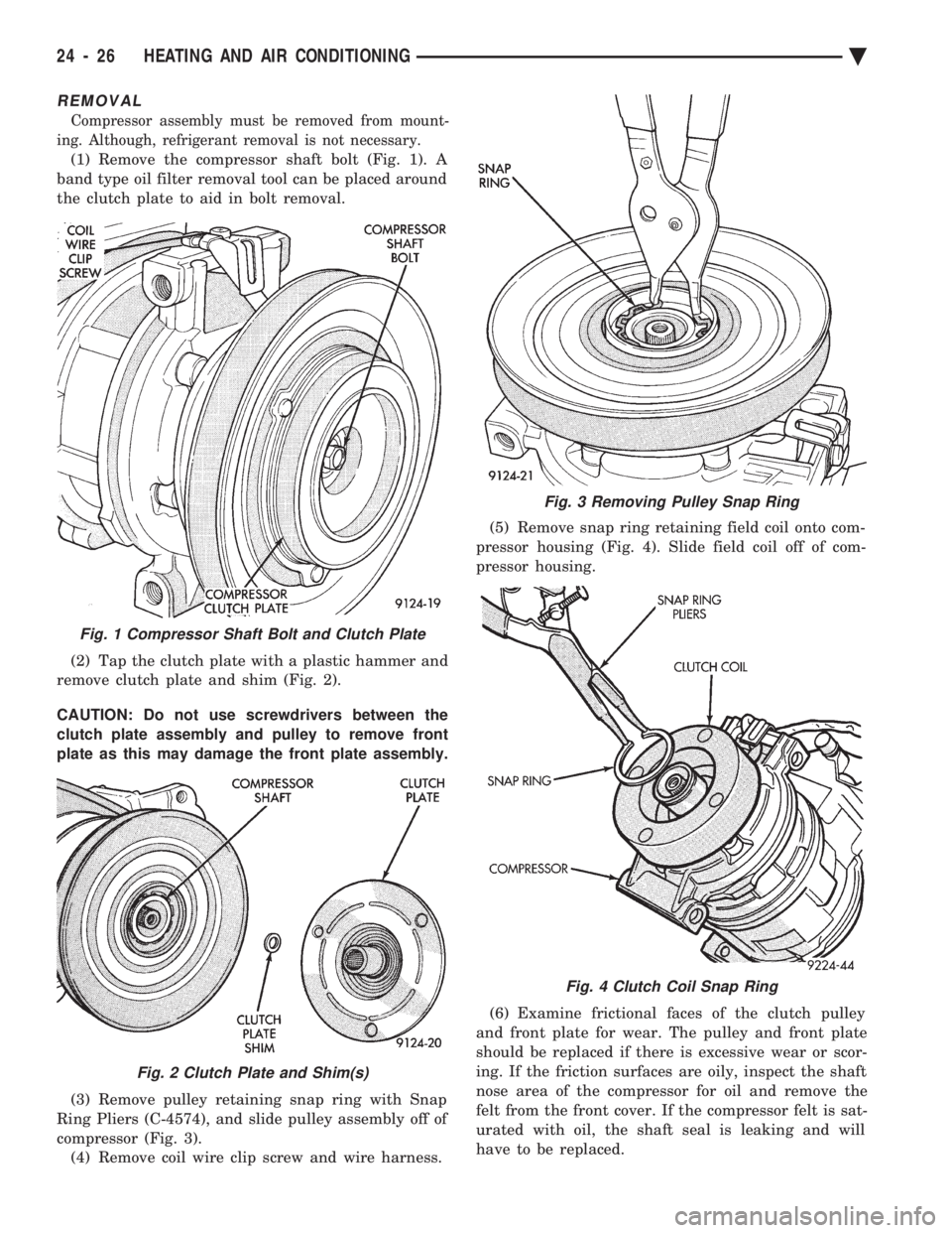
Compressor assembly must be removed from mount-
ing. Although, refrigerant removal is not necessary.
(1) Remove the compressor shaft bolt (Fig. 1). A
band type oil filter removal tool can be placed around
the clutch plate to aid in bolt removal.
(2) Tap the clutch plate with a plastic hammer and
remove clutch plate and shim (Fig. 2).
CAUTION: Do not use screwdrivers between the
clutch plate assembly and pulley to remove front
plate as this may damage the front plate assembly.
(3) Remove pulley retaining snap ring with Snap
Ring Pliers (C-4574), and slide pulley assembly off of
compressor (Fig. 3). (4) Remove coil wire clip screw and wire harness. (5) Remove snap ring retaining field coil onto com-
pressor housing (Fig. 4). Slide field coil off of com-
pressor housing.
(6) Examine frictional faces of the clutch pulley
and front plate for wear. The pulley and front plate
should be replaced if there is excessive wear or scor-
ing. If the friction surfaces are oily, inspect the shaft
nose area of the compressor for oil and remove the
felt from the front cover. If the compressor felt is sat-
urated with oil, the shaft seal is leaking and will
have to be replaced.
Fig. 1 Compressor Shaft Bolt and Clutch Plate
Fig. 2 Clutch Plate and Shim(s)
Fig. 3 Removing Pulley Snap Ring
Fig. 4 Clutch Coil Snap Ring
24 - 26 HEATING AND AIR CONDITIONING Ä
Page 2342 of 2438
FIXED DISPLACEMENT COMPRESSORÐMODEL SD709P INDEX
page page
Compressor ............................. 38
Compressor Clutch/Coil Assembly ............ 38
Compressor Shaft Seal .................... 41 Cylinder Head/Valve Plate
.................. 44
Description ............................. 38
Refrigerant System Diagnosis ............... 45
DESCRIPTION
The Sanden compressor is a 7 piston design. Sys-
tem lubrication is provided by 135 ml 615 ml (4.6 oz.
6 0.5 oz.) of 500 viscosity refrigerant oil.
The clutch used on the compressor consists of 3 ba-
sic components:
² The pulley
² Front plate
² Field coil
The pulley and field coil are attached to the front
head of the compressor with tapered snap rings. The
hub is keyed to the compressor shaft and is retained
on the shaft with a self-locking nut. Special service
tools are required to remove and install the clutch
plate on the compressor shaft.
COMPRESSOR
The A/C compressor may be removed and posi-
tioned without discharging the refrigerant system.
Discharging is not necessary if removing the A/C
compressor clutch/coil assembly, engine, cylinder
head, or generator.
WARNING: REFRIGERANT PRESSURES REMAIN
HIGH EVEN THOUGH THE ENGINE MAY BE
TURNED OFF. BEFORE REMOVING A FULLY
CHARGED COMPRESSOR, REVIEW THE SAFETY
PRECAUTIONS AND WARNINGS SECTION IN THIS
GROUP. DO NOT TWIST OR KINK THE REFRIGER-
ANT LINES WHEN REMOVING A FULLY CHARGED
COMPRESSOR. SAFETY GLASSES MUST BE
WORN.
REMOVAL
(1) Disconnect negative cable from battery.
(2) Loosen and remove drive belts (refer to group
7, Cooling System) and disconnect compressor clutch
wire lead. (3) Remove refrigerant lines from compressor (if
necessary). (4) Remove compressor attaching nuts and bolts.
(5) Remove compressor. If refrigerant lines were
not removed, lift compressor/clutch assembly and tie
it to a suitable component. To install, reverse the removal procedure.
COMPRESSOR CLUTCH/COIL ASSEMBLY
The magnetic clutch consists of a stationary elec-
tro-magnetic coil and a rotating pulley and plate as-
sembly. The electromagnetic coil is retained on the com-
pressor with a snap ring and is dimpled to maintain
its position. The pulley and plate assembly are mounted on the
compressor shaft. When the compressor is not in operation, the pul-
ley free wheels on the clutch hub bearing. When the
coil is energized the plate is magnetically engaged
with the pulley and turns the compressor shaft.
REMOVAL
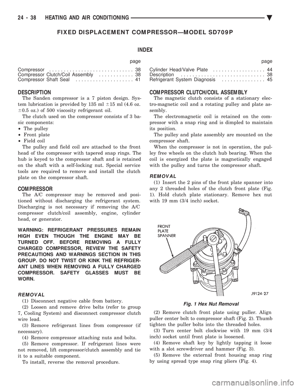
(1) Insert the 2 pins of the front plate spanner into
any 2 threaded holes of the clutch front plate (Fig.
1). Hold clutch plate stationary. Remove hex nut
with 19 mm (3/4 inch) socket.
(2) Remove clutch front plate using puller. Align
puller center bolt to compressor shaft (Fig. 2). Thumb
tighten the puller bolts into the threaded holes. (3) Turn center bolt clockwise with 19 mm (3/4
inch) socket until front plate is loosened. (4) Remove shaft key by lightly tapping it loose
with a slot screwdriver and hammer (Fig. 3). (5) Remove the external front housing snap ring
by using spread type snap ring pliers (Fig. 4).
Fig. 1 Hex Nut Removal
24 - 38 HEATING AND AIR CONDITIONING Ä
Page 2346 of 2438
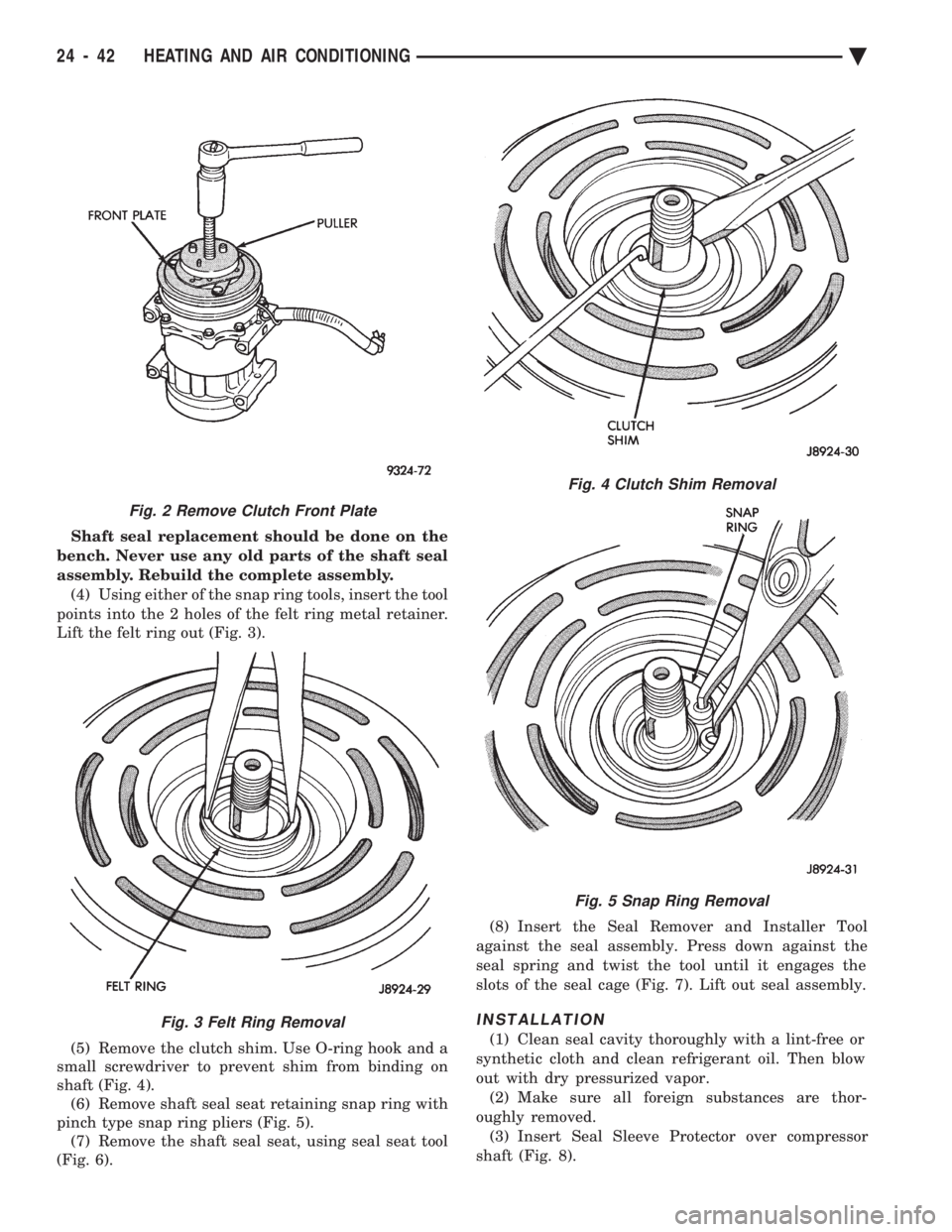
Shaft seal replacement should be done on the
bench. Never use any old parts of the shaft seal
assembly. Rebuild the complete assembly. (4) Using either of the snap ring tools, insert the tool
points into the 2 holes of the felt ring metal retainer.
Lift the felt ring out (Fig. 3).
(5) Remove the clutch shim. Use O-ring hook and a
small screwdriver to prevent shim from binding on
shaft (Fig. 4). (6) Remove shaft seal seat retaining snap ring with
pinch type snap ring pliers (Fig. 5). (7) Remove the shaft seal seat, using seal seat tool
(Fig. 6). (8) Insert the Seal Remover and Installer Tool
against the seal assembly. Press down against the
seal spring and twist the tool until it engages the
slots of the seal cage (Fig. 7). Lift out seal assembly.
INSTALLATION
(1) Clean seal cavity thoroughly with a lint-free or
synthetic cloth and clean refrigerant oil. Then blow
out with dry pressurized vapor. (2) Make sure all foreign substances are thor-
oughly removed. (3) Insert Seal Sleeve Protector over compressor
shaft (Fig. 8).
Fig. 4 Clutch Shim Removal
Fig. 5 Snap Ring Removal
Fig. 2 Remove Clutch Front Plate
Fig. 3 Felt Ring Removal
24 - 42 HEATING AND AIR CONDITIONING Ä
Page 2359 of 2438
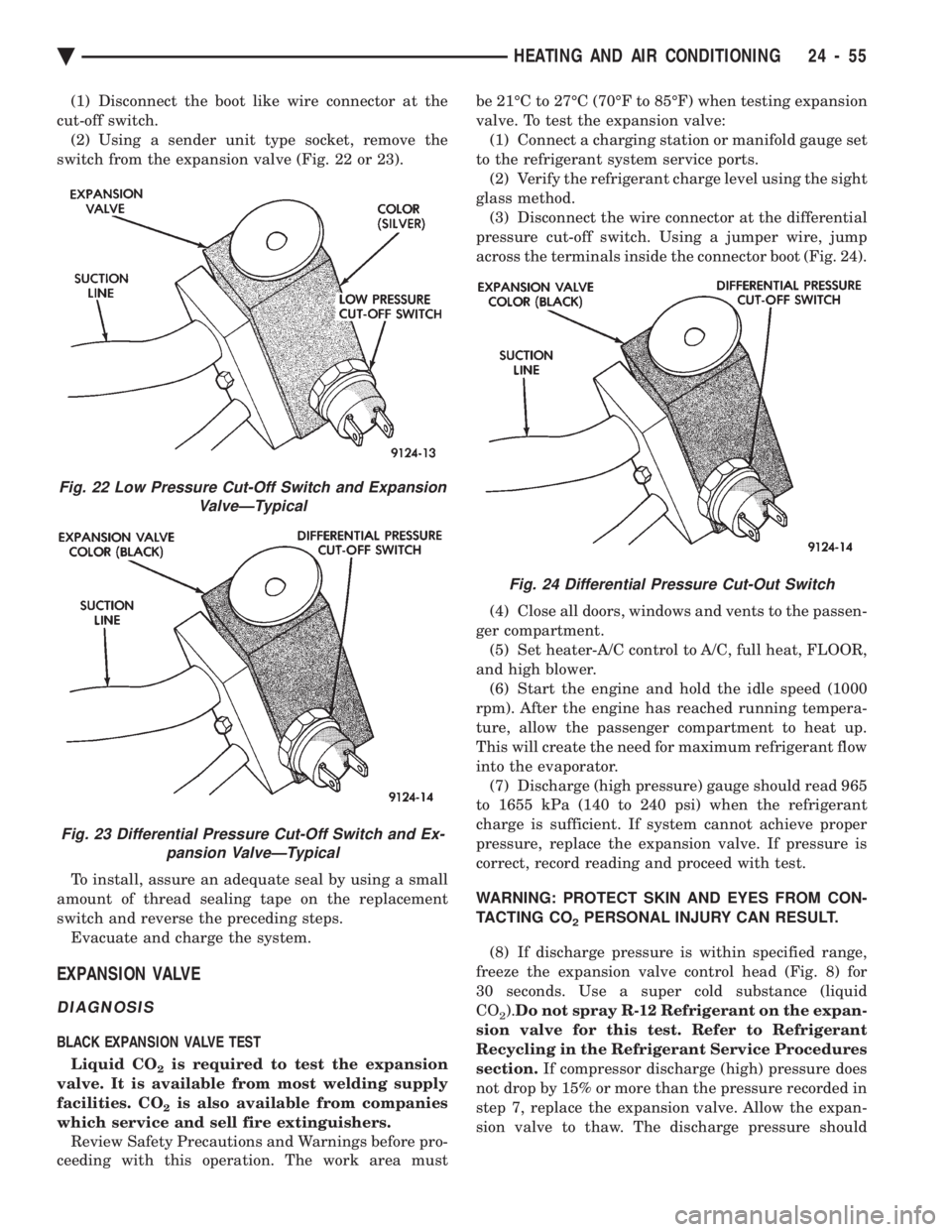
(1) Disconnect the boot like wire connector at the
cut-off switch. (2) Using a sender unit type socket, remove the
switch from the expansion valve (Fig. 22 or 23).
To install, assure an adequate seal by using a small
amount of thread sealing tape on the replacement
switch and reverse the preceding steps. Evacuate and charge the system.
EXPANSION VALVE
DIAGNOSIS
BLACK EXPANSION VALVE TEST
Liquid CO
2is required to test the expansion
valve. It is available from most welding supply
facilities. CO
2is also available from companies
which service and sell fire extinguishers. Review Safety Precautions and Warnings before pro-
ceeding with this operation. The work area must be 21ÉC to 27ÉC (70ÉF to 85ÉF) when testing expansion
valve. To test the expansion valve: (1) Connect a charging station or manifold gauge set
to the refrigerant system service ports. (2) Verify the refrigerant charge level using the sight
glass method. (3) Disconnect the wire connector at the differential
pressure cut-off switch. Using a jumper wire, jump
across the terminals inside the connector boot (Fig. 24).
(4) Close all doors, windows and vents to the passen-
ger compartment. (5) Set heater-A/C control to A/C, full heat, FLOOR,
and high blower. (6) Start the engine and hold the idle speed (1000
rpm). After the engine has reached running tempera-
ture, allow the passenger compartment to heat up.
This will create the need for maximum refrigerant flow
into the evaporator. (7) Discharge (high pressure) gauge should read 965
to 1655 kPa (140 to 240 psi) when the refrigerant
charge is sufficient. If system cannot achieve proper
pressure, replace the expansion valve. If pressure is
correct, record reading and proceed with test.
WARNING: PROTECT SKIN AND EYES FROM CON-
TACTING CO
2PERSONAL INJURY CAN RESULT.
(8) If discharge pressure is within specified range,
freeze the expansion valve control head (Fig. 8) for
30 seconds. Use a super cold substance (liquid
CO
2). Do not spray R-12 Refrigerant on the expan-
sion valve for this test. Refer to Refrigerant
Recycling in the Refrigerant Service Procedures
section. If compressor discharge (high) pressure does
not drop by 15% or more than the pressure recorded in
step 7, replace the expansion valve. Allow the expan-
sion valve to thaw. The discharge pressure should
Fig. 22 Low Pressure Cut-Off Switch and Expansion ValveÐTypical
Fig. 23 Differential Pressure Cut-Off Switch and Ex-pansion ValveÐTypical
Fig. 24 Differential Pressure Cut-Out Switch
Ä HEATING AND AIR CONDITIONING 24 - 55