1993 CHEVROLET PLYMOUTH ACCLAIM refrigerant type
[x] Cancel search: refrigerant typePage 2360 of 2438

stabilize to the pressure recorded in step 7. If the
pressure does not stabilize, replace the expansion
valve.When expansion valve tests are complete, refer to
Heater and A/C Performance Tests and remove all test
equipment before returning vehicle to use.
SILVER EXPANSION VALVE TEST
Expansion valve tests should be performed af-
ter compressor tests. Liquid CO
2is required to test the expansion
valve. It is available from most welding supply
facilities. CO
2is also available from companies
which service and sell fire extinguishers. Review Safety Precautions and Warnings in the
General Information section of this Group. The work
area and vehicle must be 21ÉC to 27ÉC (70ÉF to 85ÉF)
when testing expansion valve. To test the expansion
valve: (1) Connect a charging station or manifold gauge set
to the refrigerant system service ports. (2) Verify the refrigerant charge level using the sight
glass method. (3) Disconnect wire connector at low pressure cut-off
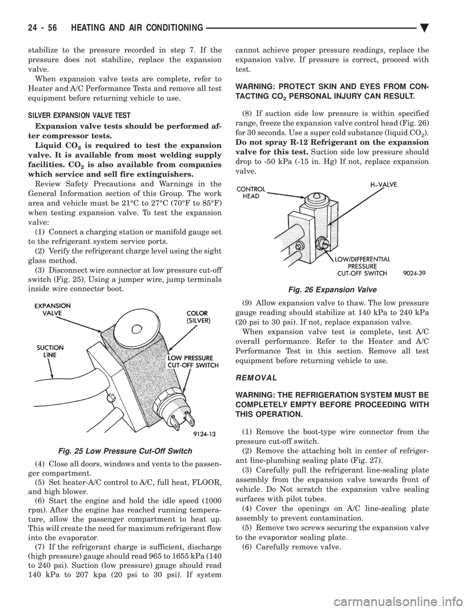
switch (Fig. 25). Using a jumper wire, jump terminals
inside wire connector boot.
(4) Close all doors, windows and vents to the passen-
ger compartment. (5) Set heater-A/C control to A/C, full heat, FLOOR,
and high blower. (6) Start the engine and hold the idle speed (1000
rpm). After the engine has reached running tempera-
ture, allow the passenger compartment to heat up.
This will create the need for maximum refrigerant flow
into the evaporator. (7) If the refrigerant charge is sufficient, discharge
(high pressure) gauge should read 965 to 1655 kPa (140
to 240 psi). Suction (low pressure) gauge should read
140 kPa to 207 kpa (20 psi to 30 psi). If system cannot achieve proper pressure readings, replace the
expansion valve. If pressure is correct, proceed with
test.
WARNING: PROTECT SKIN AND EYES FROM CON-
TACTING CO
2PERSONAL INJURY CAN RESULT.
(8) If suction side low pressure is within specified
range, freeze the expansion valve control head (Fig. 26)
for 30 seconds. Use a super cold substance (liquid CO
2).
Do not spray R-12 Refrigerant on the expansion
valve for this test. Suction side low pressure should
drop to -50 kPa (-15 in. Hg) If not, replace expansion
valve.
(9) Allow expansion valve to thaw. The low pressure
gauge reading should stabilize at 140 kPa to 240 kPa
(20 psi to 30 psi). If not, replace expansion valve. When expansion valve test is complete, test A/C
overall performance. Refer to the Heater and A/C
Performance Test in this section. Remove all test
equipment before returning vehicle to use.
REMOVAL
WARNING: THE REFRIGERATION SYSTEM MUST BE
COMPLETELY EMPTY BEFORE PROCEEDING WITH
THIS OPERATION.
(1) Remove the boot-type wire connector from the
pressure cut-off switch. (2) Remove the attaching bolt in center of refriger-
ant line-plumbing sealing plate (Fig. 27). (3) Carefully pull the refrigerant line-sealing plate
assembly from the expansion valve towards front of
vehicle. Do Not scratch the expansion valve sealing
surfaces with pilot tubes. (4) Cover the openings on A/C line-sealing plate
assembly to prevent contamination. (5) Remove two screws securing the expansion valve
to the evaporator sealing plate. (6) Carefully remove valve.
Fig. 25 Low Pressure Cut-Off Switch
Fig. 26 Expansion Valve
24 - 56 HEATING AND AIR CONDITIONING Ä
Page 2362 of 2438

new condenser, refer to Oil Level in the Refrigerant
section. Tighten the refrigerant line mounting nut to
23 N Im (200 inch pounds).
Evacuate and recharge system.
BLOWER MOTOR
BLOWER MOTOR VIBRATION AND/OR NOISE DIAGNOSIS
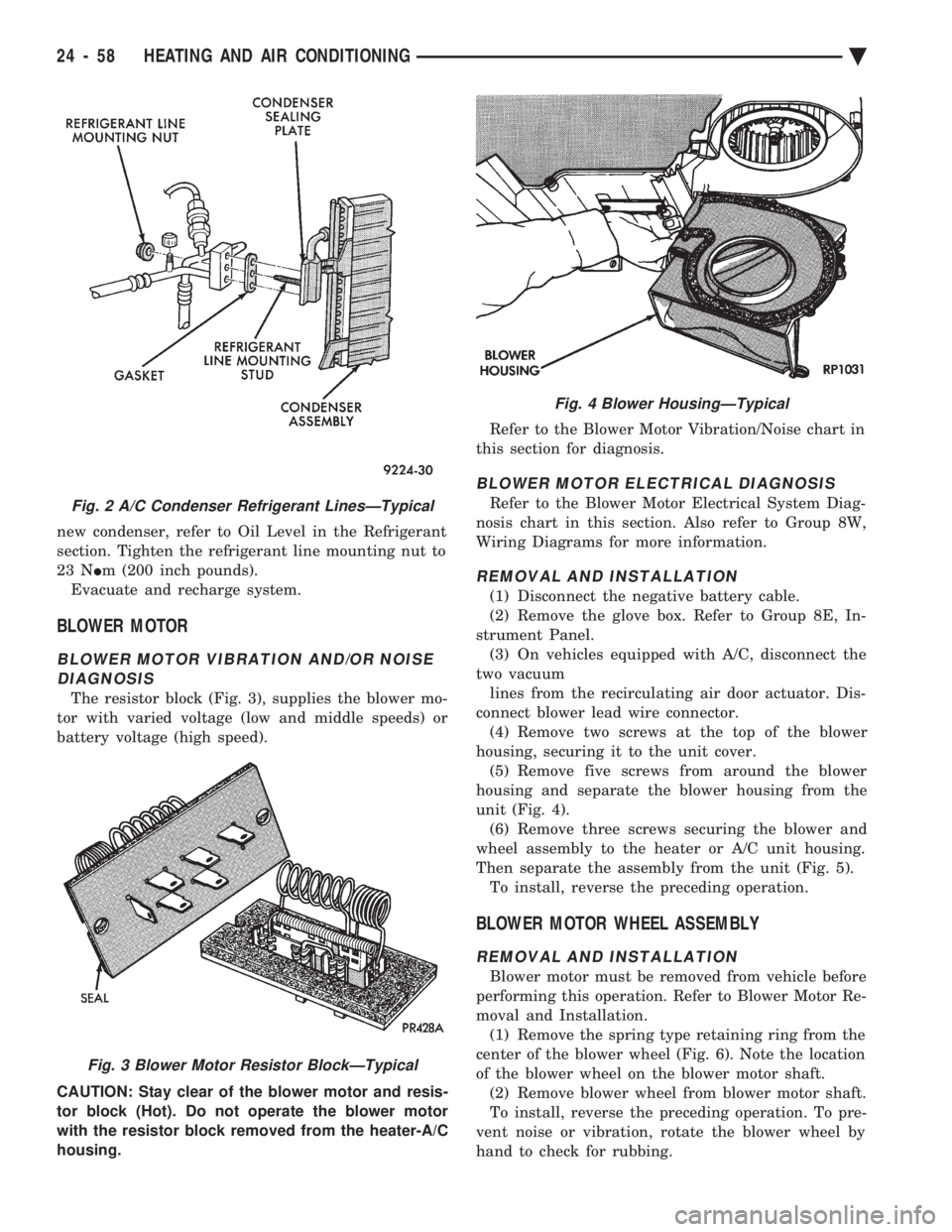
The resistor block (Fig. 3), supplies the blower mo-
tor with varied voltage (low and middle speeds) or
battery voltage (high speed).
CAUTION: Stay clear of the blower motor and resis-
tor block (Hot). Do not operate the blower motor
with the resistor block removed from the heater-A/C
housing. Refer to the Blower Motor Vibration/Noise chart in
this section for diagnosis.
BLOWER MOTOR ELECTRICAL DIAGNOSIS
Refer to the Blower Motor Electrical System Diag-
nosis chart in this section. Also refer to Group 8W,
Wiring Diagrams for more information.
REMOVAL AND INSTALLATION
(1) Disconnect the negative battery cable.
(2) Remove the glove box. Refer to Group 8E, In-
strument Panel. (3) On vehicles equipped with A/C, disconnect the
two vacuum lines from the recirculating air door actuator. Dis-
connect blower lead wire connector. (4) Remove two screws at the top of the blower
housing, securing it to the unit cover. (5) Remove five screws from around the blower
housing and separate the blower housing from the
unit (Fig. 4). (6) Remove three screws securing the blower and
wheel assembly to the heater or A/C unit housing.
Then separate the assembly from the unit (Fig. 5). To install, reverse the preceding operation.
BLOWER MOTOR WHEEL ASSEMBLY
REMOVAL AND INSTALLATION
Blower motor must be removed from vehicle before
performing this operation. Refer to Blower Motor Re-
moval and Installation. (1) Remove the spring type retaining ring from the
center of the blower wheel (Fig. 6). Note the location
of the blower wheel on the blower motor shaft. (2) Remove blower wheel from blower motor shaft.
To install, reverse the preceding operation. To pre-
vent noise or vibration, rotate the blower wheel by
hand to check for rubbing.
Fig. 2 A/C Condenser Refrigerant LinesÐTypical
Fig. 3 Blower Motor Resistor BlockÐTypical
Fig. 4 Blower HousingÐTypical
24 - 58 HEATING AND AIR CONDITIONING Ä
Page 2376 of 2438

NONÐCOMPUTER AIDED DIAGNOSTIC TESTS
Determine whether the operator complaint is due
to a system failure or improper operation of the ATC
system. The system will to go into a maximum heat
or cooling mode if the operator changes the tempera-
ture setting four or more degrees. Check the following:
² Coolant level
² Refrigerant charge
² Drive belt tension
² Radiator air flow
² Radiator fan operation
² Air suction of In-car Temperature Sensor/Aspirator
To check air suction of the Aspirator, place a small
piece of tissue paper over the Aspirator opening on
the instrument panel. This opening is located to the
right of the steering column. The tissue paper should
cling to the opening if system is functioning properly. Bring the engine to normal operating temperature
and proceed with Computer Aided Diagnostic Proce-
dures. Always test the entire system after each re-
pair has been performed.
COMPUTER AIDED DIAGNOSTIC TESTS
The ATC control has a computer capable of trou-
bleshooting the entire ATC system in approximately
60 seconds. The engine must be running and at nor-
mal operating temperature during the test to provide
hot coolant for the heater. During the ATC Diagnostic Test, the computer will
calibrate the Mode and Blend Door actuators.
CAUTION: Do not remove the actuators from the
heater-A/C unit assembly with power applied. Re-
moval should only be done with the Ignition OFF.
The actuators have no mechanical stops to limit the
travel. If the actuator rotates and is not connected
to the unit assembly, it will become un-calibrated.
The Diagnostic Test is capable of checking all elec-
trical signals between the ATC Control Module, ac-
tuators, sensors and blower control. The Diagnostic Test will display two types of Diag-
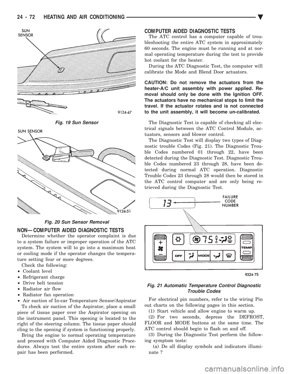
nostic trouble Codes (Fig. 21). The Diagnostic Trou-
ble Codes numbered 01 through 22, have been
detected during the Diagnostic Test. Diagnostic Trou-
ble Codes numbered 23 through 28, have been de-
tected during normal ATC operation. Diagnostic
Trouble Codes 23 through 28 would then be stored in
the ATC control computer and are only being re-
trieved during the Diagnostic Test.
For electrical pin numbers, refer to the wiring Pin
out charts on the following pages in this section. (1) Start vehicle and allow engine to warm up.
(2) For two seconds, depress the DEFROST,
FLOOR and MODE buttons at the same time. The
ATC control should begin to flash on and off. (3) During the Diagnostic Test perform the follow-
ing symptom tests: (a) Do all display symbols and indicators illumi-
nate ?
Fig. 19 Sun Sensor
Fig. 20 Sun Sensor Removal
Fig. 21 Automatic Temperature Control Diagnostic Trouble Codes
24 - 72 HEATING AND AIR CONDITIONING Ä