1993 CHEVROLET PLYMOUTH ACCLAIM catalytic converter
[x] Cancel search: catalytic converterPage 50 of 2438

PCV SYSTEM TEST
Refer to group 25, Emission Control System for
proper procedures to test PCV system.
FUEL RECOMMENDATIONS
Chrysler Corporation recommends that only fuel pur-
chased from a reputable retailer be used. Use high qual-
ity, unleaded gasoline to provide satisfactory
driveability and highest fuel economy. Gasoline contain-
ing detergent and corrosion control additives are desire-
able. If the engine develops spark knock (audible ping),
poor performance, hard starting or stalling, purchase
fuel from another source. Engine performance can vary
when using different brands of gasoline with the same
octane rating. Occasional light engine spark knock un-
der heavy acceleration, at low speed or when vehicle is
heavily loaded is not harmful. Extended periods of
spark knock under moderate acceleration or at cruising
speed can damage the engine. The cause of excessive
spark knock condition must be diagnosed and corrected.
For diagnostic procedures refer to Group 14, Fuel Sys-
tem and Powertrain Diagnostic Procedures manual.
SELECTING GASOLINE
CAUTION:Do not use fuel containing METHANOL
(methyl or wood alcohol), damage to fuel system
will result. Do not use leaded gasoline, damage to catalytic
converter will result and vehicle will not conform to
emission control standards.
ETHANOL, MTBE OR ETBE BLENDS
All Chrysler Corporation vehicles are designed to
use unleaded gasoline ONLY. Gasohol blends, con-
taining 10% Ethanol (ethyl or grain alcohol) 90% un-
leaded gasoline can be used provided it has adequate
octane rating. Fuel blends containing up to 15% MTBE (Methyl
Tertiary Butyl Ether) and 85% unleaded gasoline can
be used. Fuel blends containing up to 17% ETBE
(Ethyl Tertiary Butyl Ether) and 83% unleaded gas-
oline can also be used. Fuel blended with ethanol, MTBE or ETBE are
also referred to as reformulated or clean air gasoline.
These fuels contribute less emissions to the atmo-
sphere. Chrysler Corporation recommends that
blended fuels be used when available
METHANOL BLENDS Using gasoline blended with methanol can result
in starting and driveability problems. Deterioration
of fuel system components will result. Methanol in-
duced problems are not the responsibility of Chrysler
Corporation and may not be covered by the vehicle
warranty. NON-TURBOCHARGED ENGINES
Use regular unleaded gasoline having a minimum
octane rating of 87 (R+M)/2. Higher octane premium
unleaded gasoline can be used if desired.
2.2L 16 VALVE TURBOCHARGED ENGINE
Use premium unleaded gasoline having a mini-
mum octane rating of 91 (R+M)/2. Gasoline with oc-
tane rating less than 91 (R+M)/2 can be used if
recommended gasoline is not available. Low octane
gasoline will reduce engine performance.
FLEXIBLE FUEL VEHICLES
CAUTION: Do not use 100% methanol, damage to
fuel system can result. Use unleaded regular gasoline having a minimum
octane rating of 87 (R=M)/2 and M85 fuel that is
85% methanol and 15% unleaded gasoline, or a mix-
ture of these two.
FUEL FILTER
The fuel filter requires service only when a fuel
contamination problem is suspected. For proper diag-
nostic and service procedures refer to Group 14, Fuel
System,
IGNITION CABLES, DISTRIBUTOR CAP, AND
ROTOR
Inspect and test ignition cables, distributor cap and
rotor when the spark plugs are replaced. Oil and
grime should be cleaned from the ignition cables and
distributor cap to avoid possible spark plug fouling.
Mopar, Foamy Engine Degreaser, or equivalent is
recommended for cleaning the engine compartment.
For proper service and diagnostic procedures refer to
Group 8D, Ignition System.
SPARK PLUGS
Ignition spark plugs should be replaced at the
mileage interval described in the Lubrication and
Maintenance Schedules. Refer to the General Infor-
mation section of this group. For proper service pro-
cedures refer to Group 8D, Ignition Systems.
DRIVE BELTS
Inspect and adjust drive belts at the interval de-
scribed in the Lubrication and Maintenance Sched-
ules. Refer to General Information section of this
group. For proper inspection and adjustment proce-
dures, see Group 7, Cooling System.
EMISSION CONTROL SYSTEM
Inspect all emission control components and hoses
when other under hood service is performed. Refer to
emission system Vacuum Hose Label located on the
0 - 14 LUBRICATION AND MAINTENANCE Ä
Page 482 of 2438

(5) Disconnect electrical connector from coolant
temperature sensor. (6) Remove sensor from engine.
INSTALLATION
(1) Tighten the coolant sensor to 7 N Im (60 in. lbs.)
torque. (2) Connect electrical connector to sensor.
(3) Fill cooling system. Refer to Group 7, Cooling
System. (4) Install coil. Tighten coil mounting screws to 12
N Im (105 in. lbs.) torque.
(5) Connect electrical connector to coil.
KNOCK SENSORÐTURBO III ENGINES
The knock sensor is located on the intake manifold,
behind the PCV breather (Fig. 5).
REMOVAL
(1) Remove PCV breather.
(2) Remove harness connector from the knock sen-
sor. (3) Remove knock sensor.
INSTALLATION
(1) Install knock sensor. Tighten sensor to 9 N Im
(7 ft. lbs) torque. (2) Connect harness connector to sensor.
(3) Install PCV breather.
SPARK PLUG CABLE SERVICE
Clean high tension cables with a cloth moistened
with a non-flammable solvent. Wipe the cables dry.
Check for brittle or cracked insulation. When testing cables for punctures and cracks with
an oscilloscope, follow the instructions of the equip-
ment manufacturers.
CAUTION: Do not leave any one spark plug cable
disconnected any longer than necessary during test
or possible heat damage to catalytic converter will
occur. Total test time must not exceed ten minutes. If an oscilloscope is not available, cables can be
tested as follows: (1) With the engine not running, connect one end
of a test probe to a good ground. Use a probe made of
insulated wire and insulated alligator clips on each
end.
WARNING: THE ENGINE DIRECT IGNITION SYSTEM
GENERATES APPROXIMATELY 40,000 VOLTS.
PERSONAL INJURY COULD RESULT FROM CON-
TACT WITH THIS SYSTEM.
Fig. 3 Coolant Temperature SensorÐ3.3L and 3.3L Engine
Fig. 4 Ignition Coil Removal
Fig. 5 Knock SensorÐTurbo III Engine
8D - 40 IGNITION SYSTEMS Ä
Page 1697 of 2438

EXHAUST SYSTEM AND INTAKE MANIFOLD
CONTENTS
page page
GENERAL INFORMATION .................. 1
SERVICE PROCEDURES ................... 4 TORQUE SPECIFICATION
................. 25
GENERAL INFORMATION
Throughout this group, references may be made to
a particular vehicle by letter or number designation.
A chart showing the breakdown of these designations
is included in the Introduction Section at the front of
this service manual.
EXHAUST SYSTEMS
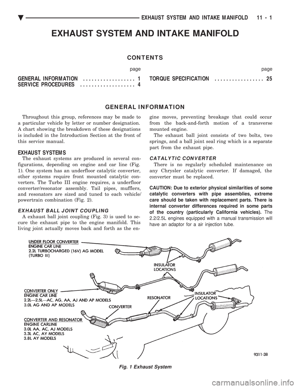
The exhaust systems are produced in several con-
figurations, depending on engine and car line (Fig.
1). One system has an underfloor catalytic converter,
other systems require front mounted catalytic con-
verters. The Turbo III engine requires, a underfloor
converter/resonator assembly. Tail pipes, mufflers,
and resonators are sized and tuned to each vehicle/
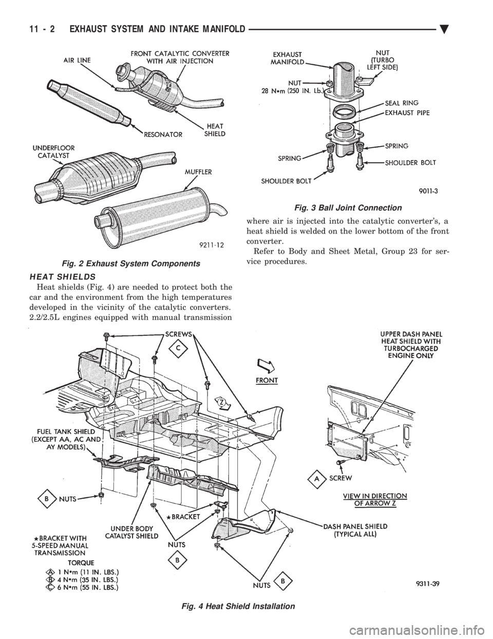
powertrain combination (Fig. 2).
EXHAUST BALL JOINT COUPLING
A exhaust ball joint coupling (Fig. 3) is used to se-
cure the exhaust pipe to the engine manifold. This
living joint actually moves back and forth as the en- gine moves, preventing breakage that could occur
from the back-and-forth motion of a transverse
mounted engine. The exhaust ball joint consists of two bolts, two
springs, and a ball joint seal ring which is a separate
part from the exhaust pipe.
CATALYTIC CONVERTER
There is no regularly scheduled maintenance on
any Chrysler catalytic converter. If damaged, the
converter must be replaced.
CAUTION: Due to exterior physical similarities of some
catalytic converters with pipe assemblies, extreme
care should be taken with replacement parts. There is
internal converter differences required in some parts
of the country (particularly California vehicles). The
2.2/2.5L engines equipped with a manual transmission will
have an adaptor for a air injection tube.
Fig. 1 Exhaust System
Ä EXHAUST SYSTEM AND INTAKE MANIFOLD 11 - 1
Page 1698 of 2438

HEAT SHIELDS
Heat shields (Fig. 4) are needed to protect both the
car and the environment from the high temperatures
developed in the vicinity of the catalytic converters.
2.2/2.5L engines equipped with manual transmission where air is injected into the catalytic converter's, a
heat shield is welded on the lower bottom of the front
converter. Refer to Body and Sheet Metal, Group 23 for ser-
vice procedures.
Fig. 3 Ball Joint Connection
Fig. 4 Heat Shield Installation
Fig. 2 Exhaust System Components
11 - 2 EXHAUST SYSTEM AND INTAKE MANIFOLD Ä
Page 1699 of 2438

CAUTION: Avoid application of rust prevention
compounds or undercoating materials to exhaust
system floor pan heat shields on cars if equipped.
Light overspray near the edges is permitted. Appli-
cation of coating will greatly reduce the efficiency
of the heat shields resulting in excessive floor pan
temperatures and objectionable fumes.
The combustion reaction caused by the catalyst re-
leases additional heat in the exhaust system. Caus-
ing temperature increases in the area of the reactor
under severe operating conditions. Such conditions
can exist when the engine misfires or otherwise does
not operate at peak efficiency. Do notremove spark
plug wires from plugs or by any other means short
out cylinders if exhaust system is equipped with cat-
alytic converter. Failure of the catalytic converter
can occur due to temperature increases caused by un-
burned fuel passing through the converter. The use of the catalysts also involves some non-au-
tomotive problems. Unleaded gasoline must be used
to avoid poisoning the catalyst core. Do not allow en- gine to operate above 1200 RPM in neutral for ex-
tended periods over 5 minutes. This condition may
result in excessive exhaust system/floor pan temper-
atures because of no air movement under the vehicle.
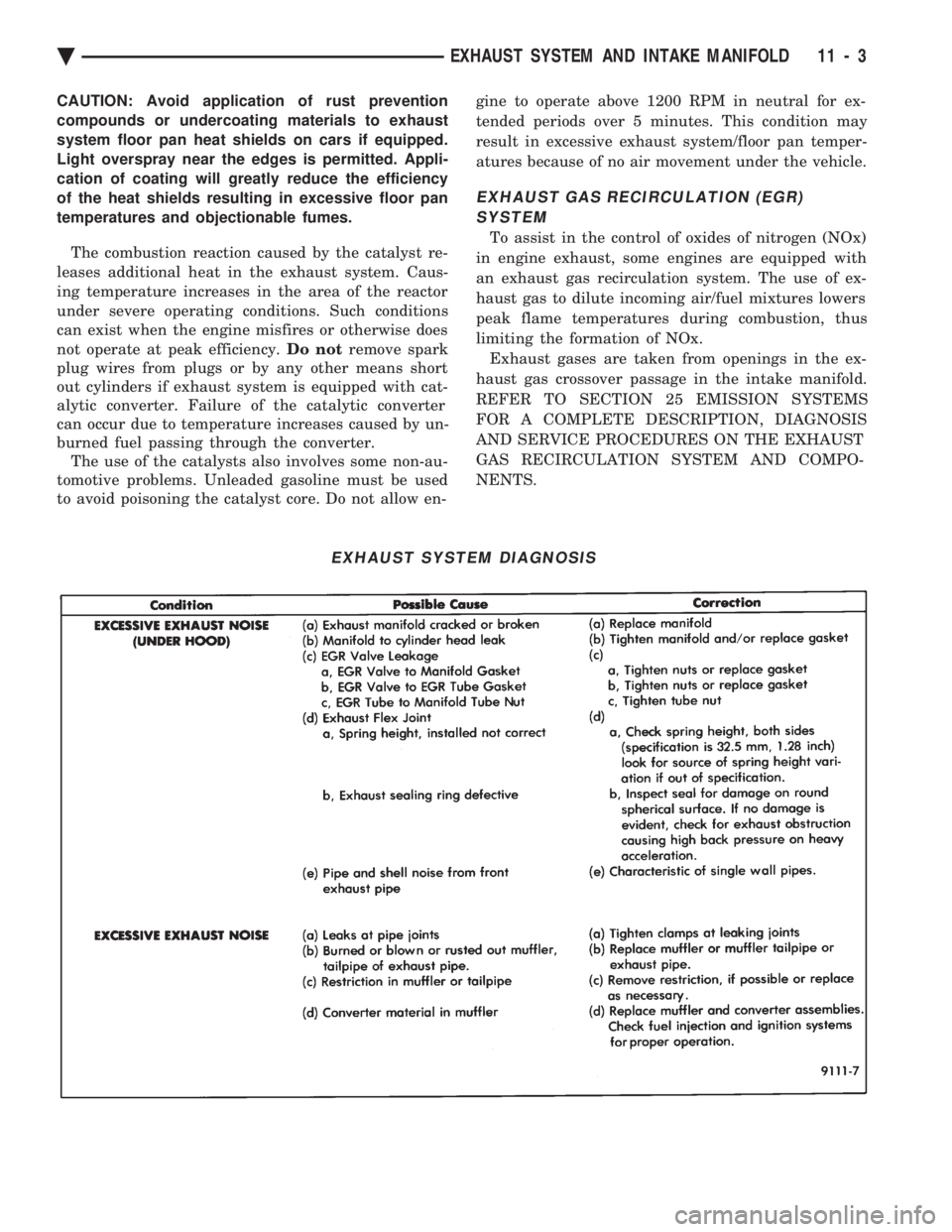
EXHAUST GAS RECIRCULATION (EGR) SYSTEM
To assist in the control of oxides of nitrogen (NOx)
in engine exhaust, some engines are equipped with
an exhaust gas recirculation system. The use of ex-
haust gas to dilute incoming air/fuel mixtures lowers
peak flame temperatures during combustion, thus
limiting the formation of NOx. Exhaust gases are taken from openings in the ex-
haust gas crossover passage in the intake manifold.
REFER TO SECTION 25 EMISSION SYSTEMS
FOR A COMPLETE DESCRIPTION, DIAGNOSIS
AND SERVICE PROCEDURES ON THE EXHAUST
GAS RECIRCULATION SYSTEM AND COMPO-
NENTS.
EXHAUST SYSTEM DIAGNOSIS
Ä EXHAUST SYSTEM AND INTAKE MANIFOLD 11 - 3