1993 CHEVROLET PLYMOUTH ACCLAIM change wheel
[x] Cancel search: change wheelPage 16 of 2438
CHRYSLER
CORPORATION
ENGINEÐCHASSISÐBODY
SERVICE MANUAL
1993 FRONT WHEEL DRIVE
PASSENGER VEHICLES
To order the special service tools used and
illustrated, please refer to the instructions on
inside back cover.
NO PART OF THIS PUBLICATION MAY BE
REPRODUCED, STORED IN A RETRIEVAL
SYSTEM, OR TRANSMITTED, IN ANY FORM
OR BY ANY MEANS, ELECTRONIC, ME-
CHANICAL, PHOTOCOPYING, RECORDING,
OR OTHERWISE, WITHOUT THE PRIOR
WRITTEN PERMISSION OF CHRYSLER
CORPORATION.
Chrysler Corporation reserves the right to make changes in design or to make
additions to or improvements in its products without imposing any obligations
upon itself to install them on its products previously manufactured.
Litho in U.S.A. Copyright 1992 Chrysler Corporation 30M0792
NEXT PAGE©
Page 17 of 2438
FOREWORD
The information contained in this service manual has been prepared for the professional automotive
technician involved in daily repair operations. This manual does not cover theory of operation, which is addressed
in service training material. Information describing the operation and use of standard and optional equipment is
included in the Owner's Manual provided with the vehicle.
Information in this manual is divided into groups. These groups contain general information, diagnosis,
testing, adjustments, removal, installation, disassembly, and assembly procedures for the components.
The Component and System Index of this manual identifies the correct group for the component or system to
be serviced. To assist in locating a group title page, use the Group Tab Locator on the following page. The solid bar
after the group title is aligned to a solid tab on the first page of each group. The first page of the group has a
contents section that lists major topics within the group.
A Service Manual Comment form is included at the rear of this manual. Use the form to provide Chrysler
Corporation with your comments and suggestions.
Tightening torques are provided as a specific value throughout this manual. This value represents the
midpoint of the acceptable engineering torque range for a given fastener application. These torque values are
intended for use in service assembly and installation procedures using the correct OEM fasteners. When replacing
fasteners, always use the same type (part number) fastener as removed.
Chrysler Corporation reserves the right to change testing procedures, specifications, diagnosis, repair
methods, or vehicle wiring at any time without prior notice or incurring obligation.
NOTE: The acronyms, terminology and nomenclature used to identify emissions related components in this
manual may have changed from prior publications. These new terms are in compliance with S.A.E.
recommended practice J1930. This terminology standard (J1930) is required to comply with the 1993
California Air Research Board (CARB) requirements.
FOR INFORMATION NOT CONTAINED IN THIS MANUAL, REFER TO FRONT WHEEL DRIVE
PASSENGER VEHICLES ELECTRICALÐFUELÐEMISSIONS OR WIRING DIAGRAMS SERVICE
MANUALS.
NEXT PAGE©
Page 20 of 2438
CHRYSLER
CORPORATION
ELECTRICALÐFUELÐ
EMISSION SYSTEMS SERVICE MANUAL
1993 FRONT WHEEL DRIVE PASSENGER VEHICLES
To order the special service tools used and
illustrated, please refer to the instructions on
inside back cover.
NO PART OF THIS PUBLICATION MAY BE
REPRODUCED, STORED IN A RETRIEVAL
SYSTEM, OR TRANSMITTED, IN ANY FORM
OR BY ANY MEANS, ELECTRONIC, ME-
CHANICAL, PHOTOCOPYING, RECORDING,
OR OTHERWISE, WITHOUT THE PRIOR
WRITTEN PERMISSION OF CHRYSLER
CORPORATION.
Chrysler Corporation reserves the right to make changes in design or to make
additions to or improvements in its products without imposing any obligations
upon itself to install them on its products previously manufactured.
Litho in U.S.A. Copyright 1992 Chrysler Corporation 30M0792
NEXT PAGE ©
Page 21 of 2438
FOREWORD
The information contained in this service manual has been prepared for the professional automotive
technician involved in daily repair operations. This manual does not cover theory of operation, which is addressed
in service training material. Information describing the operation and use of standard and optional equipment is
included in the Owner's Manual provided with the vehicle.
Information in this manual is divided into groups. These groups contain general information, diagnosis,
testing, adjustments, removal, installation, disassembly, and assembly procedures for the components.
The Component and System Index of this manual identifies the correct group for the component or system to
be serviced. To assist in locating a group title page, use the Group Tab Locator on the following page. The solid bar
after the group title is aligned to a solid tab on the first page of each group. The first page of the group has a
contents section that lists major topics within the group.
A Service Manual Comment form is included at the rear of this manual. Use the form to provide Chrysler
Corporation with your comments and suggestions.
Tightening torques are provided as a specific value throughout this manual. This value represents the
midpoint of the acceptable engineering torque range for a given fastener application. These torque values are
intended for use in service assembly and installation procedures using the correct OEM fasteners. When replacing
fasteners, always use the same type (part number) fastener as removed.
Chrysler Corporation reserves the right to change testing procedures, specifications, diagnosis, repair
methods, or vehicle wiring at any time without prior notice or incurring obligation.
NOTE: The acronyms, terminology and nomenclature used to identify emissions related components in this
manual may have changed from prior publications. These new terms are in compliance with S.A.E.
recommended practice J1930. This terminology standard (J1930) is required to comply with the 1993
California Air Research Board (CARB) requirements.
FOR INFORMATION NOT CONTAINED IN THIS MANUAL, REFER TO FRONT WHEEL DRIVE
PASSENGER VEHICLES ENGINEÐCHASSISÐBODY OR WIRING DIAGRAMS SERVICE MANUALS.
NEXT PAGE ©
Page 24 of 2438

CHRYSLER
CORPORATION
SERVICE MANUAL
SUPPLEMENT
BENDIX ANTILOCK 4 BRAKE SYSTEM
1993 FRONT WHEEL DRIVE CAR
This manual supplements the 1993 Front-
Wheel-Drive Car Service Manual 81-270-3101,
and contains the service information on the new
Bendix Antilock 4 brake system. The Bendix
Antilock 4 brake system only affects the LeBaron
Landau, Spirit, Acclaim and LeBaron Coupe and
Convertible built at the Newark Assembly Plant
after April 19, 1993. Any of these model vehicles
built at other assembly plants, will continue to
use carryover antilock brake systems for the
remainder of the 1993 model year.
To order the special service tools used and
illustrated, please refer to the instructions on
inside back cover.
NO PART
OF THIS PUBLICATION MAY BE REPRO-
DUCED, STORED IN A RETRIEVAL SYSTEM,
OR TRANSMITTED, IN ANY FORM OR BY ANY
MEANS, ELECTRONIC, MECHANICAL, PHO-
TOCOPYING, RECORDING, OR OTHERWISE,
WITHOUT THE PRIOR WRITTEN PERMIS-
SION OF CHRYSLER CORPORATION.
Chrysler Corporation reserves the right to make changes in design or to make
additions to or improvements in its products without imposing any obligations
upon itself to install them on its products previously manufactured.
Litho in U.S.A. Copyright 1993 Chrysler Corporation 30M0393
NEXT PAGE ©
Page 28 of 2438
CHRYSLER
CORPORATION
WIRING DIAGRAMS
SERVICE MANUAL
1993 FRONT WHEEL DRIVE PASSENGER VEHICLES
To order the special service tools used and
illustrated, please refer to the instructions on
inside back cover.
NO PART OF THIS PUBLICATION MAY BE
REPRODUCED, STORED IN A RETRIEVAL
SYSTEM, OR TRANSMITTED, IN ANY FORM
OR BY ANY MEANS, ELECTRONIC, ME-
CHANICAL, PHOTOCOPYING, RECORDING,
OR OTHERWISE, WITHOUT THE PRIOR
WRITTEN PERMISSION OF CHRYSLER
CORPORATION.
Chrysler Corporation reserves the right to make changes in design or to make
additions to or improvements in its products without imposing any obligations
upon itself to install them on its products previously manufactured.
Litho in U.S.A. Copyright 1992 Chrysler Corporation 30M0792
NEXT PAGE ©
Page 29 of 2438

FOREWORD
The information contained in this Service Manual has been prepared for the professional automotive
technician involved in daily repair operations. Information describing the operation and use of standard and
optional equipment is included in the Owner's Manual provided with the vehicle.
These diagrams contain the latest information at the time of publication and incorporate the wiring schematic
for the basic vehicle and available optional equipment.
The diagrams are grouped by body type and sales division. The body codes are explained in the General
Information section. (ExampleÐAP-D, P=Shadow, Sundance). To locate a system or component refer to the black
index tabs on the next page. The tab will assist you in locating the desired area of the manual.
An alphabetical index is provided at the beginning of each section to help you in locating a system or
component. All diagrams are identified by SHEET NUMBER which is found in the lower right- or left-hand corner
of the page.
A Service Manual Comment form is included at the rear of this manual. Use the form to provide Chrysler
Corporation with your comments and suggestions.
Chrysler Corporation reserves the right to change testing procedures, specifications, diagnosis, repair
methods, or vehicle wiring at any time without prior notice or incurring obligation.
NOTE: The acronyms, terminology and nomenclature used to identify emissions related components in this
manual may have changed from prior publications. These new terms are in compliance with S.A.E.
recommended practice J1930. This terminology standard (J1930) is required to comply with the 1993
California Air Research Board (CARB) requirements.
FOR INFORMATION NOT CONTAINED IN THIS MANUAL, REFER TO THE FRONT WHEEL
DRIVE PASSENGER VEHICLES ENGINEÐCHASSISÐBODY OR ELECTRICALÐFUELÐEMISSIONS
SERVICE MANUALS.
NEXT PAGE ©
Page 52 of 2438
DRIVETRAIN INDEX
page page
Automatic Transaxle ...................... 16
Automatic Transaxle Floor Shift .............. 16
Clutch and Gearshift Linkage ............... 16
Drive Shaft Cv and Tripod Joint Boots ........ 17 Front Wheel Bearings
..................... 17
Manual Transaxle ........................ 16
Tires .................................. 17
CLUTCH AND GEARSHIFT LINKAGE
If the clutch or gearshift begins to operate with dif-
ficulty, squeak or grunt, the cables and linkage
should be lubricated before service replacement is
performed. For proper lubrication and service proce-
dures refer to Group 6, Clutch, or Group 21, Manual
Transaxle.
MANUAL TRANSAXLE
The manual transaxle should be inspected for oil
leaks and proper oil level when other under vehicle
service is performed. To inspect the transaxle oil
level, position the vehicle on a level surface. Remove
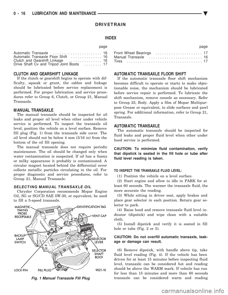
fill plug (Fig. 1) from the transaxle side cover. The
oil level should not be below 4 mm (3/16 in) from the
bottom of the oil fill opening. The manual transaxle does not require periodic
maintenance. The oil should be changed only when
water contamination is suspected. If oil has a foamy
or milky appearance it probably is contaminated. A
circular magnet located behind the differential cover
collects metallic particles circulating in the oil. For
proper diagnostic and service procedures, refer to
Group 21, Manual Transaxle.
SELECTING MANUAL TRANSAXLE OIL
Chrysler Corporation recommends Mopar Engine
Oil, SG or SG/CD SAE 5W-30, or equivalent, be used
to fill a 5-speed transaxle.
AUTOMATIC TRANSAXLE FLOOR SHIFT
If the automatic transaxle floor shift mechanism
becomes difficult to operate or starts to make objec-
tionable noise, the mechanism should be lubricated
before service repair is performed. To lubricate the
shift mechanism, remove console as necessary. Refer
to Group 23, Body. Apply a film of Mopar Multipur-
pose Grease or equivalent, to slide surfaces and pawl
spring. For additional information, refer to Group 21,
Transaxle.
AUTOMATIC TRANSAXLE
The automatic transaxle should be inspected for
fluid leaks and proper fluid level when other under
hood service is performed.
CAUTION: To minimize fluid contamination, verify
that dipstick is seated in the fill hole or tube after
fluid level reading is taken.
TO INSPECT THE TRANSAXLE FLUID LEVEL: (1) Position the vehicle on a level surface.
(2) Start engine and allow to idle in PARK for at
least 60 seconds. The warmer the transaxle fluid, the
more accurate the reading. (3) While sitting in driver seat, apply brakes and
place gear selector in each position. Return gear se-
lector to park. (4) Raise hood and remove transaxle fluid level in-
dicator (dipstick) and wipe clean with a suitable
cloth. (5) Install dipstick and verify it is seated in fill
hole or tube (Fig. 2 or 3).
CAUTION: Do not overfill automatic transaxle, leak-
age or damage can result.
(6) Remove dipstick, with handle above tip, take
fluid level reading (Fig. 4). If the vehicle has been
driven for at least 15 minutes before inspecting fluid
level, transaxle can be considered hot and reading
should be above the WARM mark. If vehicle has run
for less than 15 minutes and more than 60 seconds
transaxle can be considered warm and reading
Fig. 1 Manual Transaxle Fill Plug
0 - 16 LUBRICATION AND MAINTENANCE Ä