1993 CHEVROLET PLYMOUTH ACCLAIM instrument panel
[x] Cancel search: instrument panelPage 22 of 2438
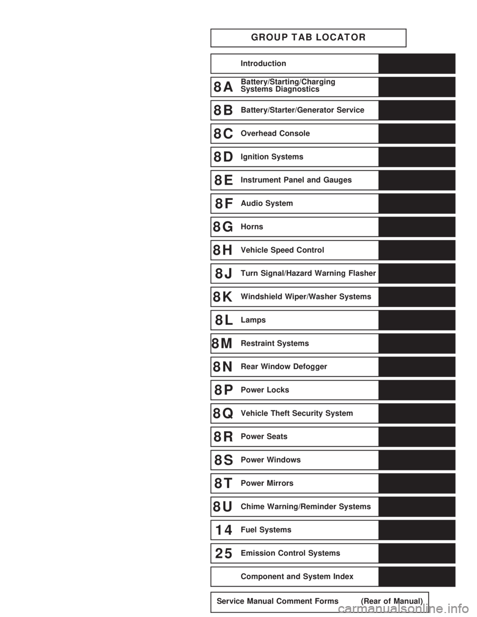
GROUP TAB LOCATOR
Introduction
8ABattery/Starting/Charging
Systems Diagnostics
8BBattery/Starter/Generator Service
8COverhead Console
8DIgnition Systems
8EInstrument Panel and Gauges
8FAudio System
8GHorns
8HVehicle Speed Control
8JTurn Signal/Hazard Warning Flasher
8KWindshield Wiper/Washer Systems
8LLamps
8MRestraint Systems
8NRear Window Defogger
8PPower Locks
8QVehicle Theft Security System
8RPower Seats
8SPower Windows
8TPower Mirrors
8UChime Warning/Reminder Systems
14Fuel Systems
25Emission Control Systems
Component and System Index
Service Manual Comment Forms (Rear of Manual)
Page 33 of 2438

COMPONENT AND SYSTEM INDEX
Name Group-page Name Group-page
AUDIO SYSTEM ............................ 8F-1
ANTENNAS ............................ 8F-20
COMPACT DISC PLAYER ................... 8F-30
RADIOS ............................... 8F-1
SPEAKERS ............................. 8F-24
BATTERY/STARTER/GENERATOR SERVICE ..........8B-1
BATTERY REMOVAL, INSTALLATION AND SERVICE . . 8B-1
GENERATOR ............................ 8B-9
SPECIFICATIONS ........................ 8B-12
STARTER .............................. 8B-4
BATTERY/STARTING/CHARGING SYSTEMS DIAGNOSTICS ........................... 8A-1
BATTERY TEST PROCEDURES ON-VEHICLE .......8A-3
FAULT CODESÐON BOARD DIAGNOSTICS .......8A-23
GENERAL INFORMATION .................... 8A-1
GENERATOR TEST PROCEDURES ON VEHICLE ....8A-19
IGNITION OFF DRAW (IOD) ..................8A-9
SPECIFICATIONS ........................ 8A-28
STARTER TEST PROCEDURES ON VEHICLE ......8A-11
CHIME WARNING/REMINDER SYSTEM ............8U-1
EMISSION CONTROL SYSTEMS .................25-1
EVAPORATIVE EMISSION CONTROLS ...........25-1
EXHAUST EMISSION CONTROLS ..............25-17
FUEL SYSTEMS ............................ 14-1
2.2L TURBO III MULTI-PORT FUEL INJECTIONÐ GENERAL DIAGNOSIS ................... 14-95
2.2L TURBO III MULTI-PORT FUEL INJECTIONÐ ON-BOARD DIAGNOSTICS ................14-100
2.2L TURBO III MULTI-PORT FUEL INJECTIONÐ SERVICE PROCEDURES .................14-107
2.2L TURBO III MULTI-PORT FUEL INJECTIONÐ SYSTEM OPERATION .................... 14-83
2.2L/2.5L SINGLE POINT FUEL INJECTIONÐ GENERAL DIAGNOSIS ................... 14-35
2.2L/2.5L SINGLE POINT FUEL INJECTIONÐ ON-BOARD DIAGNOSTICS .................14-41
2.2L/2.5L SINGLE POINT FUEL INJECTIONÐ SERVICE PROCEDURES .................. 14-48
2.2L/2.5L SINGLE POINT FUEL INJECTIONÐ SYSTEM OPERATION .................... 14-24
2.5L FLEXIBLE FUEL MULTI-PORT FUEL INJECTIONÐGENERAL DIAGNOSIS ..........14-66
2.5L FLEXIBLE FUEL MULTI-PORT FUEL INJECTIONÐON-BOARD DIAGNOSTICS ........14-70
2.5L FLEXIBLE FUEL MULTI-PORT FUEL INJECTIONÐSERVICE PROCEDURES .........14-77
2.5L FLEXIBLE FUEL MULTI-PORT FUEL INJECTIONÐSYSTEM OPERATION ...........14-55
3.0L MULTI-PORT FUEL INJECTIONÐGENERAL DIAGNOSIS .......................... 14-125
3.0L MULTI-PORT FUEL INJECTIONÐON-BOARD DIAGNOSTICS ........................ 14-130
3.0L MULTI-PORT FUEL INJECTIONÐSERVICE PROCEDURES ........................ 14-138
3.0L MULTI-PORT FUEL INJECTIONÐSYSTEM OPERATION ......................... 14-113
3.3L AND 3.8L MULTI-PORT FUEL INJECTIONÐ GENERAL DIAGNOSIS ................... 14-157 3.3L AND 3.8L MULTI-PORT FUEL INJECTIONÐ
ON-BOARD DIAGNOSTICS ................14-162
3.3L AND 3.8L MULTI-PORT FUEL INJECTIONÐ SERVICE PROCEDURES .................14-169
3.3L AND 3.8L MULTI-PORT FUEL INJECTIONÐ SYSTEM OPERATION ................... 14-145
ACCELERATOR PEDAL AND THROTTLE CABLE ....14-21
FUEL DELIVERY SYSTEM .................... 14-3
FUEL TANKS ........................... 14-14
GENERAL INFORMATION .................... 14-1
SPECIFICATIONS ........................ 14-178
HORNS ................................. 8G-1
IGNITION SYSTEMS ......................... 8D-1
2.2L TBI, 2.5L TBI, 2.5L MPI AND 3.0L IGNITION SYSTEMSÐDIAGNOSTIC PROCEDURES .......8D-11
2.2L TBI, 2.5L TBI, 2.5L MPI AND 3.0L IGNITION SYSTEMSÐSERVICE PROCEDURES ..........8D-14
2.2L TBI, 2.5L TBI, 2.5L MPI AND 3.0L IGNITION SYSTEMSÐSYSTEM OPERATION ............8D-1
2.2L TURBO III, 3.3L AND 3.8L IGNITION SYSTEMÐDIAGNOSTIC PROCEDURES ........8D-35
2.2L TURBO III, 3.3L AND 3.8L IGNITION SYSTEMÐSYSTEM OPERATION ............8D-24
2.2L TURBO III, 3.3L AND 3.8L IGNITION SYSTEMSÐSERVICE PROCEDURES ..........8D-39
IGNITION SWITCH ....................... 8D-45
SPECIFICATIONS ........................ 8D-47
INSTRUMENT PANEL AND GAUGES ...............8E-1
AA BODY .............................. 8E-1
AC AND AY BODIES ...................... 8E-23
AG AND AJ BODIES ...................... 8E-42
AP BODY ............................. 8E-58
LAMPS .................................. 8L-1
BULB APPLICATION TABLE ..................8L-38
CONCEALED HEADLAMPS ..................8L-27
EXTERIOR LAMP SWITCHES AND HEADLAMP ALIGNMENT ........................... 8L-3
EXTERIOR LAMP SYSTEMS .................8L-25
EXTERIOR LAMPSÐAA BODY ................8L-7
EXTERIOR LAMPSÐAC BODY ...............8L-10
EXTERIOR LAMPSÐAG BODY ...............8L-14
EXTERIOR LAMPSÐAJ BODY ................8L-16
EXTERIOR LAMPSÐAP BODY ...............8L-19
EXTERIOR LAMPSÐAY-BODY ................8L-22
GENERAL INFORMATION .................... 8L-1
ILLUMINATED ENTRY SYSTEM ...............8L-33
OVERHEAD CONSOLE ........................ 8C-1
AA BODY .............................. 8C-1
AC AND AY BODY ........................ 8C-6
AG AND AJ BODIES ...................... 8C-13
AP BODY ............................. 8C-21
POWER LOCKS ............................ 8P-1
POWER MIRRORS ..........................8T-1
POWER SEATS ............................ 8R-1
POWER WINDOWS .......................... 8S-1
REAR WINDOW DEFOGGER .................... 8N-1
RESTRAINT SYSTEMS ....................... 8M-1
TURN SIGNALS AND HAZARD WARNING FLASHER ....8J-1
VEHICLE SPEED CONTROL .................... 8H-1
Page 176 of 2438

HYDRAULIC SYSTEM CONTROL VALVES INDEX
page page
ABS Brake Proportioning Valve Operation ...... 27
General Information ....................... 26
Hydraulic System Service Procedures ......... 27 Non-ABS Proportioning Unit Operation
........ 26
Pressure Differential Warning Light Switch ...... 26
Testing ABS Proportioning Valves ............ 29
GENERAL INFORMATION
Most models not equipped with an Anti-Lock brak-
ing system have a combination hydraulic system con-
trol valve in the brake hydraulic system (Fig. 1). The
valve is attached to the frame rail below the master
cylinder.
The control valve assembly combines a warning
switch with a dual proportioning valve (Fig. 2) Proportioning valves balance front to rear braking
by controlling at a given ratio, the increase in rear
system hydraulic pressure above a preset level. Un-
der light pedal application, the valve allows full hy-
draulic pressure to the rear brakes. There is only one valve assembly in each vehicle,
see Valve Application Chart. During any service pro-
cedures identify valve assemblies by part number as
well as split point (PSI) and slope.
PRESSURE DIFFERENTIAL WARNING LIGHT
SWITCH
The hydraulic brake system, on non-ABS vehicles,
is split diagonally. The left front and right rear
brakes are part of one system. And the right front and left rear are part of another. Both systems are
routed through, but hydraulically separated by a Pres-
sure Differential Switch. The function of the Pressure
Differential Switch is to alert the driver of a malfunc-
tion in the brake system. If hydraulic pressure is lost in one system, the
warning light switch will activate a red light on the
instrument panel, when the brake pedal is depressed.
At this point the brakes require service. However, since
the brake systems are split diagonally the vehicle will
retain 50% of its stopping capability in the event of a
failure in either half. The warning light switch is the latching type. It
will automatically center itself after the repair is
made and the brake pedal is depressed. The instrument panel bulb can be checked each time
the ignition switch is turned to the start position or the
parking brake is set.
NON-ABS PROPORTIONING UNIT OPERATION
The proportioning valve section operates by trans-
mitting full input pressure to the rear brakes up to a
certain point. This is called the split point. Beyond this
point it reduces the amount of pressure increase to the
rear brakes according to a certain ratio. On light pedal applications equal brake pressure will
be transmitted to the front and rear brakes. On heavier
pedal applications the pressure transmitted
Fig. 1 Brake Combination Valve And Warning Switch Location
Fig. 2 Switch and Valve Assembly
5 - 26 BRAKES Ä
Page 216 of 2438

MASTER CYLINDER INDEX
page page
Brake Fluid Level Sensor .................. 66
General Information ....................... 66 Master Cylinder Service Procedures
.......... 67
Testing the Master Cylinder ................. 66
GENERAL INFORMATION
The tandem master cylinder (Fig. 1) has a glass re-
inforced nylon reservoir and an anodized aluminum
body. Do not hone the bore of the cylinder, as this will
remove the anodized surface. The reservoir is indexed to prevent installation in
the wrong direction (Fig. 2). The cap diaphragms are
slit to allow atmospheric pressure to equalize on both
sides of the diaphragm. The primary and secondary outlet tubes from the
master cylinder are connected to the valve mounted
under the master cylinder. The front part of this
block connects to the secondary outlet tube and sup-
plies the right rear and left front brakes. The rear
portion of the block connects to the primary outlet
tube and supplies the right front and left rear
brakes.
BRAKE FLUID LEVEL SENSOR
The Brake Fluid Level sensor is found only in the
AJ body vehicles with the visual electronic message
center. The purpose of the sensor is to provide the
driver with an early warning message that brake
fluid in master cylinder reservoir has dropped to a
below normal. As the fluid drops below the design level the sensor
closes the warning message circuit. Approximately
15 seconds later the message BRAKE FLUID LOW
appears on the instrument panel. At this time the master cylinder reservoir should be checked and filled
to the bottom of the rings with DOT 3 brake fluid. To check the operation of the Brake Fluid Level
sensor, with ignition on and wiring still attache-
d,remove sensor from master cylinder and hold in
upright position. Within 30 seconds the instrument
panel message BRAKE FLUID LOW should appear.
Next invert the sensor. The instrument panel message
should turn off immediately. If the above sequence
occurs the sensor is operating properly. If the message
does not appear remove the wiring from the sensor and
using a jumper wire connect both sides of the plug. The
instrumental panel message BRAKE FLUID LOW
should appear within 30 seconds. If the message does
not appear a problem exists in the wiring or instru-
mentation. If the message does appear the sensor is
faulty and must be replaced. The Brake Fluid Level
sensor is not a repairable item (Fig. 2).
TESTING THE MASTER CYLINDER
Be sure master cylinder vents at both ports.
Apply pedal lightly with engine running and look for
fluid squirting or swirling into reservoirs. In this master cylinder, a special baffle reduces the
amount of fluid entering the secondary reservoir only a
small disturbance may be seen.
Fig. 1 Aluminum Master Cylinder (Cutaway View)
Fig. 2 Brake Fluid Level Sensor
5 - 66 BRAKES Ä
Page 219 of 2438
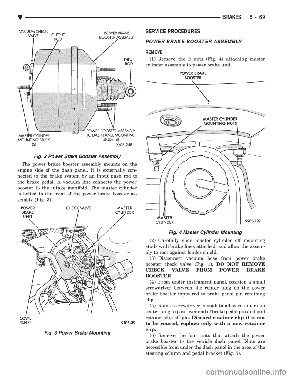
The power brake booster assembly mounts on the
engine side of the dash panel. It is externally con-
nected to the brake system by an input push rod to
the brake pedal. A vacuum line connects the power
booster to the intake manifold. The master cylinder
is bolted to the front of the power brake booster as-
sembly (Fig. 3).
SERVICE PROCEDURES
POWER BRAKE BOOSTER ASSEMBLY
REMOVE
(1) Remove the 2 nuts (Fig. 4) attaching master
cylinder assembly to power brake unit.
(2) Carefully slide master cylinder off mounting
studs with brake lines attached, and allow the assem-
bly to rest against fender shield. (3) Disconnect vacuum hose from power brake
booster check valve (Fig. 1). DO NOT REMOVE
CHECK VALVE FROM POWER BRAKE
BOOSTER. (4) From under instrument panel, position a small
screwdriver between the center tang on the power
brake booster input rod to brake pedal pin retaining
clip. (5) Rotate screwdriver enough to allow retainer clip
center tang to pass over end of brake pedal pin and pull
retainer clip off pin. Discard retainer clip it is not
to be reused, replace only with a new retainer
clip. (6) Remove the four nuts that attach the power
brake booster to the vehicle dash panel. Nuts are
accessible from under the dash panel in the area of the
steering column and pedal bracket (Fig. 5).
Fig. 2 Power Brake Booster Assembly
Fig. 3 Power Brake Mounting
Fig. 4 Master Cylinder Mounting
Ä BRAKES 5 - 69
Page 247 of 2438
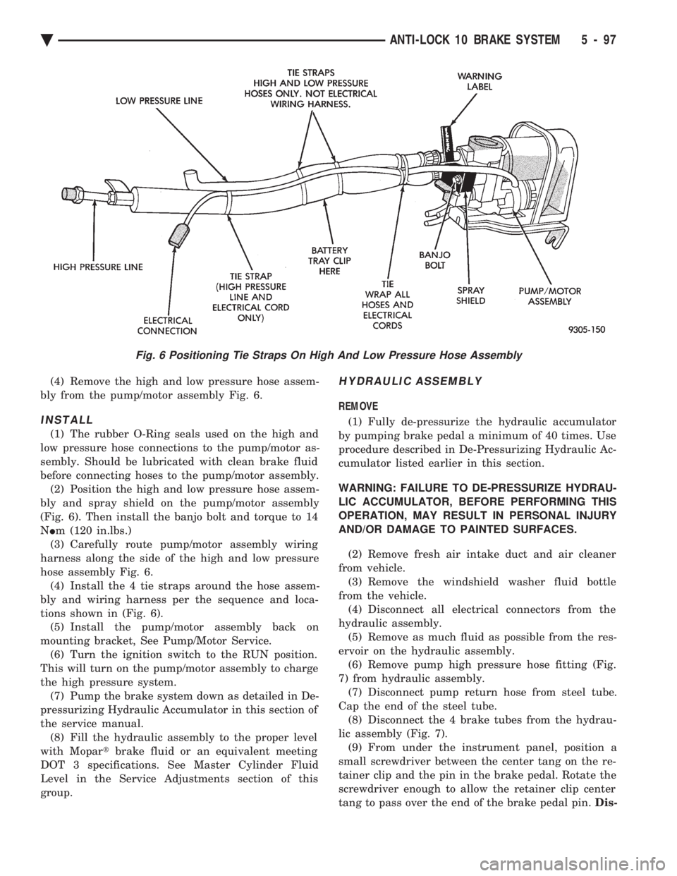
(4) Remove the high and low pressure hose assem-
bly from the pump/motor assembly Fig. 6.
INSTALL
(1) The rubber O-Ring seals used on the high and
low pressure hose connections to the pump/motor as-
sembly. Should be lubricated with clean brake fluid
before connecting hoses to the pump/motor assembly. (2) Position the high and low pressure hose assem-
bly and spray shield on the pump/motor assembly
(Fig. 6). Then install the banjo bolt and torque to 14
N Im (120 in.lbs.)
(3) Carefully route pump/motor assembly wiring
harness along the side of the high and low pressure
hose assembly Fig. 6. (4) Install the 4 tie straps around the hose assem-
bly and wiring harness per the sequence and loca-
tions shown in (Fig. 6). (5) Install the pump/motor assembly back on
mounting bracket, See Pump/Motor Service. (6) Turn the ignition switch to the RUN position.
This will turn on the pump/motor assembly to charge
the high pressure system. (7) Pump the brake system down as detailed in De-
pressurizing Hydraulic Accumulator in this section of
the service manual. (8) Fill the hydraulic assembly to the proper level
with Mopar tbrake fluid or an equivalent meeting
DOT 3 specifications. See Master Cylinder Fluid
Level in the Service Adjustments section of this
group.
HYDRAULIC ASSEMBLY
REMOVE
(1) Fully de-pressurize the hydraulic accumulator
by pumping brake pedal a minimum of 40 times. Use
procedure described in De-Pressurizing Hydraulic Ac-
cumulator listed earlier in this section.
WARNING: FAILURE TO DE-PRESSURIZE HYDRAU-
LIC ACCUMULATOR, BEFORE PERFORMING THIS
OPERATION, MAY RESULT IN PERSONAL INJURY
AND/OR DAMAGE TO PAINTED SURFACES.
(2) Remove fresh air intake duct and air cleaner
from vehicle. (3) Remove the windshield washer fluid bottle
from the vehicle. (4) Disconnect all electrical connectors from the
hydraulic assembly. (5) Remove as much fluid as possible from the res-
ervoir on the hydraulic assembly. (6) Remove pump high pressure hose fitting (Fig.
7) from hydraulic assembly. (7) Disconnect pump return hose from steel tube.
Cap the end of the steel tube. (8) Disconnect the 4 brake tubes from the hydrau-
lic assembly (Fig. 7). (9) From under the instrument panel, position a
small screwdriver between the center tang on the re-
tainer clip and the pin in the brake pedal. Rotate the
screwdriver enough to allow the retainer clip center
tang to pass over the end of the brake pedal pin. Dis-
Fig. 6 Positioning Tie Straps On High And Low Pressure Hose Assembly
Ä ANTI-LOCK 10 BRAKE SYSTEM 5 - 97
Page 248 of 2438
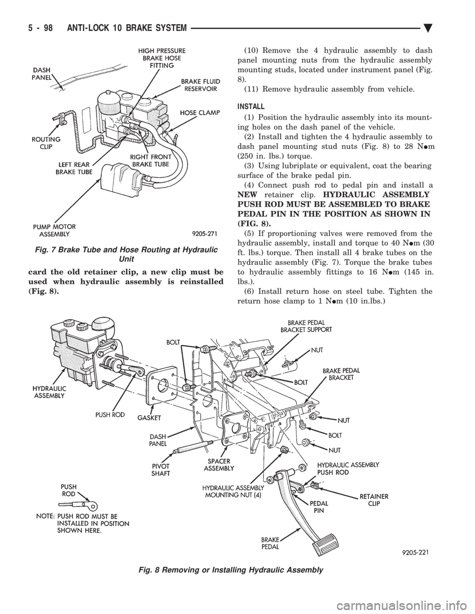
card the old retainer clip, a new clip must be
used when hydraulic assembly is reinstalled
(Fig. 8). (10) Remove the 4 hydraulic assembly to dash
panel mounting nuts from the hydraulic assembly
mounting studs, located under instrument panel (Fig.
8). (11) Remove hydraulic assembly from vehicle.
INSTALL (1) Position the hydraulic assembly into its mount-
ing holes on the dash panel of the vehicle. (2) Install and tighten the 4 hydraulic assembly to
dash panel mounting stud nuts (Fig. 8) to 28 N Im
(250 in. lbs.) torque. (3) Using lubriplate or equivalent, coat the bearing
surface of the brake pedal pin. (4) Connect push rod to pedal pin and install a
NEW retainer clip. HYDRAULIC ASSEMBLY
PUSH ROD MUST BE ASSEMBLED TO BRAKE
PEDAL PIN IN THE POSITION AS SHOWN IN
(FIG. 8). (5) If proportioning valves were removed from the
hydraulic assembly, install and torque to 40 N Im (30
ft. lbs.) torque. Then install all 4 brake tubes on the
hydraulic assembly (Fig. 7). Torque the brake tubes
to hydraulic assembly fittings to 16 N Im (145 in.
lbs.). (6) Install return hose on steel tube. Tighten the
return hose clamp to 1 N Im (10 in.lbs.)
Fig. 7 Brake Tube and Hose Routing at Hydraulic
Unit
Fig. 8 Removing or Installing Hydraulic Assembly
5 - 98 ANTI-LOCK 10 BRAKE SYSTEM Ä
Page 270 of 2438
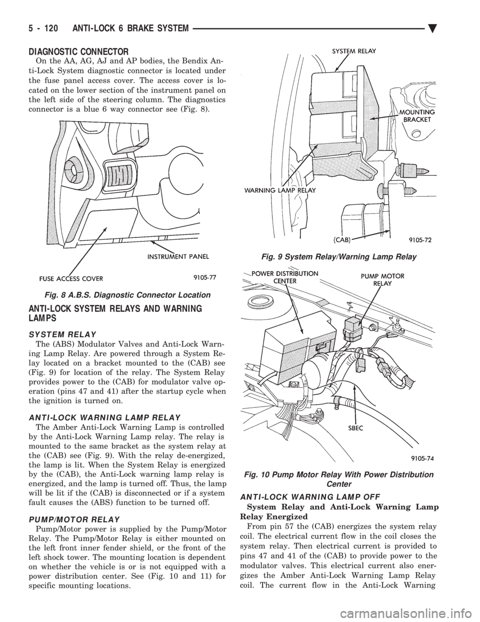
DIAGNOSTIC CONNECTOR
On the AA, AG, AJ and AP bodies, the Bendix An-
ti-Lock System diagnostic connector is located under
the fuse panel access cover. The access cover is lo-
cated on the lower section of the instrument panel on
the left side of the steering column. The diagnostics
connector is a blue 6 way connector see (Fig. 8).
ANTI-LOCK SYSTEM RELAYS AND WARNING
LAMPS
SYSTEM RELAY
The (ABS) Modulator Valves and Anti-Lock Warn-
ing Lamp Relay. Are powered through a System Re-
lay located on a bracket mounted to the (CAB) see
(Fig. 9) for location of the relay. The System Relay
provides power to the (CAB) for modulator valve op-
eration (pins 47 and 41) after the startup cycle when
the ignition is turned on.
ANTI-LOCK WARNING LAMP RELAY
The Amber Anti-Lock Warning Lamp is controlled
by the Anti-Lock Warning Lamp relay. The relay is
mounted to the same bracket as the system relay at
the (CAB) see (Fig. 9). With the relay de-energized,
the lamp is lit. When the System Relay is energized
by the (CAB), the Anti-Lock warning lamp relay is
energized, and the lamp is turned off. Thus, the lamp
will be lit if the (CAB) is disconnected or if a system
fault causes the (ABS) function to be turned off.
PUMP/MOTOR RELAY
Pump/Motor power is supplied by the Pump/Motor
Relay. The Pump/Motor Relay is either mounted on
the left front inner fender shield, or the front of the
left shock tower. The mounting location is dependent
on whether the vehicle is or is not equipped with a
power distribution center. See (Fig. 10 and 11) for
specific mounting locations.
ANTI-LOCK WARNING LAMP OFF
System Relay and Anti-Lock Warning Lamp
Relay Energized From pin 57 the (CAB) energizes the system relay
coil. The electrical current flow in the coil closes the
system relay. Then electrical current is provided to
pins 47 and 41 of the (CAB) to provide power to the
modulator valves. This electrical current also ener-
gizes the Amber Anti-Lock Warning Lamp Relay
coil. The current flow in the Anti-Lock Warning
Fig. 8 A.B.S. Diagnostic Connector Location
Fig. 9 System Relay/Warning Lamp Relay
Fig. 10 Pump Motor Relay With Power Distribution Center
5 - 120 ANTI-LOCK 6 BRAKE SYSTEM Ä