1993 CHEVROLET PLYMOUTH ACCLAIM engine oil capacity
[x] Cancel search: engine oil capacityPage 40 of 2438
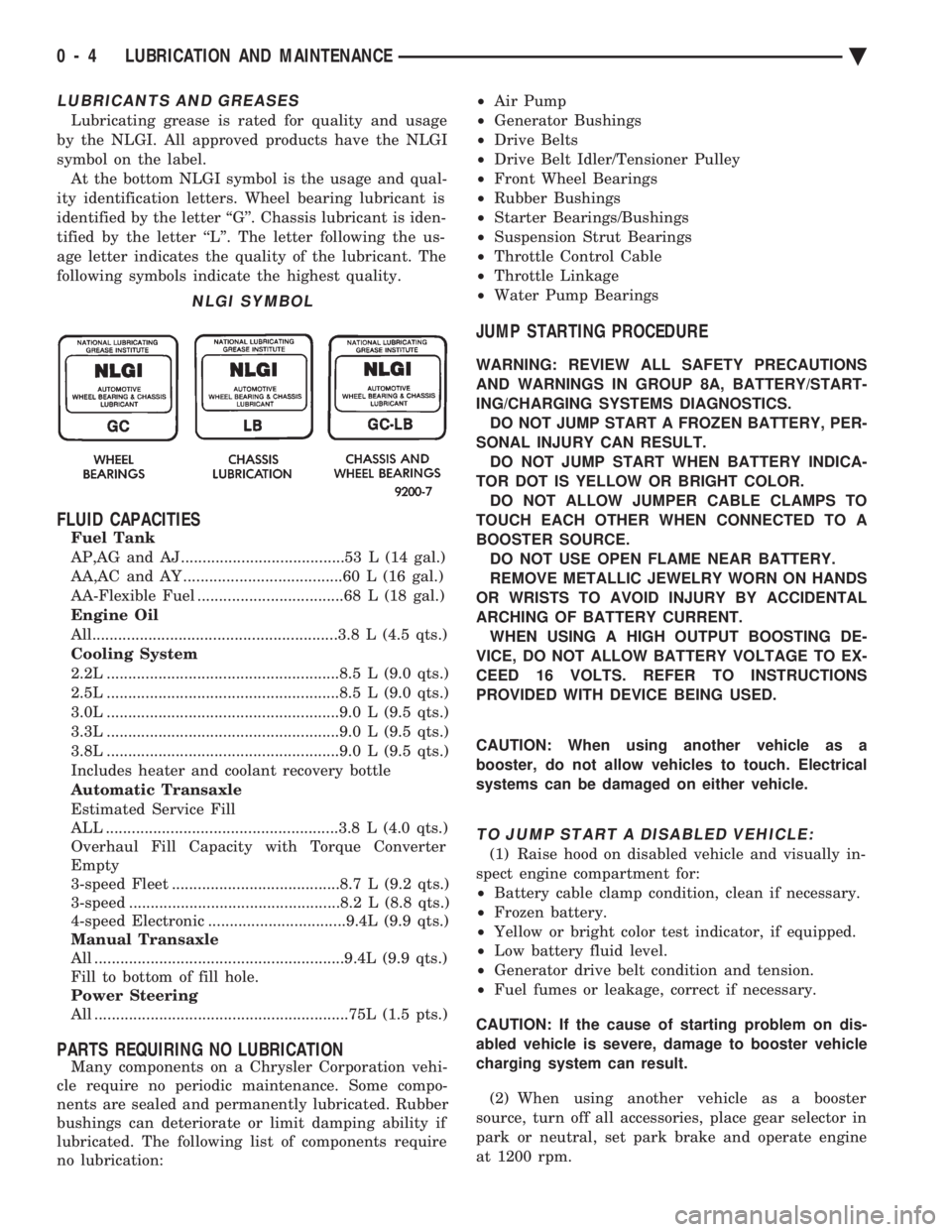
LUBRICANTS AND GREASES
Lubricating grease is rated for quality and usage
by the NLGI. All approved products have the NLGI
symbol on the label. At the bottom NLGI symbol is the usage and qual-
ity identification letters. Wheel bearing lubricant is
identified by the letter ``G''. Chassis lubricant is iden-
tified by the letter ``L''. The letter following the us-
age letter indicates the quality of the lubricant. The
following symbols indicate the highest quality.
FLUID CAPACITIES
Fuel Tank
AP,AG and AJ ......................................53 L (14 gal.)
AA,AC and AY .....................................60 L (16 gal.)
AA-Flexible Fuel ..................................68 L (18 gal.)
Engine Oil
All.........................................................3.8 L (4.5 qts.)
Cooling System
2.2L ......................................................8.5 L (9.0 qts.)
2.5L ......................................................8.5 L (9.0 qts.)
3.0L ......................................................9.0 L (9.5 qts.)
3.3L ......................................................9.0 L (9.5 qts.)
3.8L ......................................................9.0 L (9.5 qts.)
Includes heater and coolant recovery bottle
Automatic Transaxle
Estimated Service Fill
ALL ......................................................3.8 L (4.0 qts.)
Overhaul Fill Capacity with Torque Converter
Empty
3-speed Fleet .......................................8.7 L (9.2 qts.)
3-speed .................................................8.2 L (8.8 qts.)
4-speed Electronic ................................9.4L (9.9 qts.)
Manual Transaxle
All ..........................................................9.4L (9.9 qts.)
Fill to bottom of fill hole.
Power Steering
All ...........................................................75L (1.5 pts.)
PARTS REQUIRING NO LUBRICATION
Many components on a Chrysler Corporation vehi-
cle require no periodic maintenance. Some compo-
nents are sealed and permanently lubricated. Rubber
bushings can deteriorate or limit damping ability if
lubricated. The following list of components require
no lubrication: ²
Air Pump
² Generator Bushings
² Drive Belts
² Drive Belt Idler/Tensioner Pulley
² Front Wheel Bearings
² Rubber Bushings
² Starter Bearings/Bushings
² Suspension Strut Bearings
² Throttle Control Cable
² Throttle Linkage
² Water Pump Bearings
JUMP STARTING PROCEDURE
WARNING: REVIEW ALL SAFETY PRECAUTIONS
AND WARNINGS IN GROUP 8A, BATTERY/START-
ING/CHARGING SYSTEMS DIAGNOSTICS. DO NOT JUMP START A FROZEN BATTERY, PER-
SONAL INJURY CAN RESULT. DO NOT JUMP START WHEN BATTERY INDICA-
TOR DOT IS YELLOW OR BRIGHT COLOR. DO NOT ALLOW JUMPER CABLE CLAMPS TO
TOUCH EACH OTHER WHEN CONNECTED TO A
BOOSTER SOURCE. DO NOT USE OPEN FLAME NEAR BATTERY.
REMOVE METALLIC JEWELRY WORN ON HANDS
OR WRISTS TO AVOID INJURY BY ACCIDENTAL
ARCHING OF BATTERY CURRENT. WHEN USING A HIGH OUTPUT BOOSTING DE-
VICE, DO NOT ALLOW BATTERY VOLTAGE TO EX-
CEED 16 VOLTS. REFER TO INSTRUCTIONS
PROVIDED WITH DEVICE BEING USED.
CAUTION: When using another vehicle as a
booster, do not allow vehicles to touch. Electrical
systems can be damaged on either vehicle.
TO JUMP START A DISABLED VEHICLE:
(1) Raise hood on disabled vehicle and visually in-
spect engine compartment for:
² Battery cable clamp condition, clean if necessary.
² Frozen battery.
² Yellow or bright color test indicator, if equipped.
² Low battery fluid level.
² Generator drive belt condition and tension.
² Fuel fumes or leakage, correct if necessary.
CAUTION: If the cause of starting problem on dis-
abled vehicle is severe, damage to booster vehicle
charging system can result.
(2) When using another vehicle as a booster
source, turn off all accessories, place gear selector in
park or neutral, set park brake and operate engine
at 1200 rpm.
NLGI SYMBOL
0 - 4 LUBRICATION AND MAINTENANCE Ä
Page 47 of 2438
tifreeze to achieve adequate protection. A mix table
on the coolant container indicates the amount of an-
tifreeze required to winterize the cooling system
based on the capacity, see Capacity Chart in General
Information section of this group.
SELECTING ANTIFREEZE
Chrysler Corporation recommends Mopar Anti-
freeze/Summer Coolant, or equivalent be used to win-
terize and protect cooling system.
RADIATOR CAP
The radiator cap must be secure to provide proper
pressure release and coolant recovery. Inspect and
test radiator cap when cooling system service is per-
formed or when problem is suspected.
COOLING SYSTEM SERVICE
The cooling system should be drained, flushed and
filled with the proper coolant mixture at the inter-
vals described in the Lubrication and Maintenance
Schedules. Refer to General Information section of
this group. For proper service instructions see Group
7, Cooling System.
ENGINE AIR CLEANER
The engine air cleaner should be serviced at the in-
tervals described in the Lubrication and Mainte-
nance Schedules. Refer to General Information
section of this group. Additional information can be
found in Group 14, Fuel System and Group 25, Emis-
sion System. Inspect all air cleaner hoses or tubes for
damage or leaks when other engine compartment
service is performed. Replace faulty components.
AIR CLEANER SERVICE
CAUTION: The air cleaner cover must be installed
properly for the emissions system and engine con-
troller to function correctly. Do not immerse paper air filter element or temper-
ature sensor in cleaning solvents, damage can re-
sult.
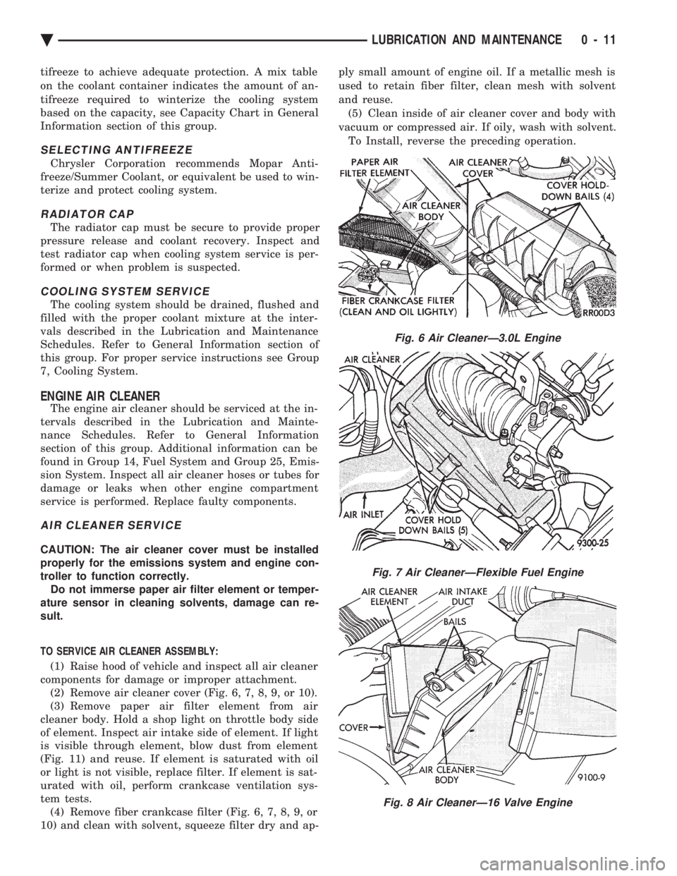
TO SERVICE AIR CLEANER ASSEMBLY: (1) Raise hood of vehicle and inspect all air cleaner
components for damage or improper attachment. (2) Remove air cleaner cover (Fig. 6, 7, 8, 9, or 10).
(3) Remove paper air filter element from air
cleaner body. Hold a shop light on throttle body side
of element. Inspect air intake side of element. If light
is visible through element, blow dust from element
(Fig. 11) and reuse. If element is saturated with oil
or light is not visible, replace filter. If element is sat-
urated with oil, perform crankcase ventilation sys-
tem tests. (4) Remove fiber crankcase filter (Fig. 6, 7, 8, 9, or
10) and clean with solvent, squeeze filter dry and ap- ply small amount of engine oil. If a metallic mesh is
used to retain fiber filter, clean mesh with solvent
and reuse.
(5) Clean inside of air cleaner cover and body with
vacuum or compressed air. If oily, wash with solvent. To Install, reverse the preceding operation.
Fig. 6 Air CleanerÐ3.0L Engine
Fig. 7 Air CleanerÐFlexible Fuel Engine
Fig. 8 Air CleanerÐ16 Valve Engine
Ä LUBRICATION AND MAINTENANCE 0 - 11
Page 102 of 2438
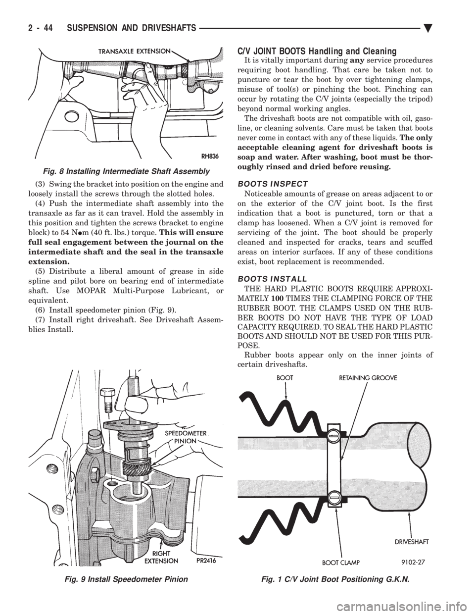
(3) Swing the bracket into position on the engine and
loosely install the screws through the slotted holes. (4) Push the intermediate shaft assembly into the
transaxle as far as it can travel. Hold the assembly in
this position and tighten the screws (bracket to engine
block) to 54 N Im (40 ft. lbs.) torque. This will ensure
full seal engagement between the journal on the
intermediate shaft and the seal in the transaxle
extension. (5) Distribute a liberal amount of grease in side
spline and pilot bore on bearing end of intermediate
shaft. Use MOPAR Multi-Purpose Lubricant, or
equivalent. (6) Install speedometer pinion (Fig. 9).
(7) Install right driveshaft. See Driveshaft Assem-
blies Install.
C/V JOINT BOOTS Handling and Cleaning
It is vitally important during anyservice procedures
requiring boot handling. That care be taken not to
puncture or tear the boot by over tightening clamps,
misuse of tool(s) or pinching the boot. Pinching can
occur by rotating the C/V joints (especially the tripod)
beyond normal working angles.
The driveshaft boots are not compatible with oil, gaso-
line, or cleaning solvents. Care must be taken that boots
never come in contact with any of these liquids. The only
acceptable cleaning agent for driveshaft boots is
soap and water. After washing, boot must be thor-
oughly rinsed and dried before reusing.
BOOTS INSPECT
Noticeable amounts of grease on areas adjacent to or
on the exterior of the C/V joint boot. Is the first
indication that a boot is punctured, torn or that a
clamp has loosened. When a C/V joint is removed for
servicing of the joint. The boot should be properly
cleaned and inspected for cracks, tears and scuffed
areas on interior surfaces. If any of these conditions
exist, boot replacement is recommended.
BOOTS INSTALL
THE HARD PLASTIC BOOTS REQUIRE APPROXI-
MATELY 100TIMES THE CLAMPING FORCE OF THE
RUBBER BOOT. THE CLAMPS USED ON THE RUB-
BER BOOTS DO NOT HAVE THE TYPE OF LOAD
CAPACITY REQUIRED. TO SEAL THE HARD PLASTIC
BOOTS AND SHOULD NOT BE USED FOR THIS PUR-
POSE.
Rubber boots appear only on the inner joints of
certain driveshafts.
Fig. 9 Install Speedometer PinionFig. 1 C/V Joint Boot Positioning G.K.N.
Fig. 8 Installing Intermediate Shaft Assembly
2 - 44 SUSPENSION AND DRIVESHAFTS Ä
Page 360 of 2438

RADIATOR PRESSURE CAP
Radiators are equipped with a pressure cap which
releases pressure at some point within a range of
97-124 kPa (14-18 psi) (Fig. 7). The system will operate at higher than atmospheric
pressure which raises the coolant boiling point allow-
ing increased radiator cooling capacity. There is also a vent valve in the center of the cap that
allows a small coolant flow to the CRS tank. If valve is
stuck shut, the radiator hoses will be collapsed
on cool down. Clean the vent valve (Fig. 7) to
ensure proper sealing when boiling point is
reached.
There is also a gasket in the cap to seal to the top of
the filler neck so that vacuum can be maintained for
drawing coolant back into the radiator from the coolant
reserve system tank.
RADIATOR CAP TO FILLER NECK SEAL PRES- SURE RELIEF CHECK
The pressure cap upper gasket (seal) pressure relief
can be checked by removing the overflow hose at the
radiator filler neck nipple (Fig. 7). Attach the Radiator
Pressure Tool to the filler neck nipple and pump air
into the radiator. Pressure cap upper gasket should
relieve at 69-124 kPa (10-18 psi) and hold pressure at
55 kPa (8 psi) minimum.
WARNING: THE WARNING WORDS DO NOT OPEN
HOT ON THE RADIATOR PRESSURE CAP IS A
SAFETY PRECAUTION. WHEN HOT, PRESSURE
BUILDS UP IN COOLING SYSTEM. TO PREVENT
SCALDING OR INJURY, THE RADIATOR CAP
SHOULD NOT BE REMOVED WHILE THE SYSTEM IS
HOT AND/OR UNDER PRESSURE.
There is no need to remove the radiator cap at any
time except for the following purposes:
(1) Check and adjust antifreeze freeze point.
(2) Refill system with new antifreeze.
(3) Conducting service procedures.
(4) Checking for vacuum leaks.
WARNING: IF VEHICLE HAS BEEN RUN RECENTLY,
WAIT 15 MINUTES BEFORE REMOVING CAP. THEN PLACE A SHOP TOWEL OVER THE CAP AND WITH-
OUT PUSHING DOWN ROTATE IT COUNTER-
CLOCKWISE TO THE FIRST STOP. ALLOW FLUIDS
TO ESCAPE THROUGH THE OVERFLOW TUBE AND
WHEN THE SYSTEM STOPS PUSHING COOLANT
AND STEAM INTO THE CRS TANK AND PRESSURE
DROPS PUSH DOWN AND REMOVE THE CAP COM-
PLETELY. SQUEEZING THE RADIATOR INLET HOSE
WITH A SHOP TOWEL (TO CHECK PRESSURE) BE-
FORE AND AFTER TURNING TO THE FIRST STOP IS
RECOMMENDED.
PRESSURE TESTING RADIATOR CAPS
Dip the pressure cap in water, clean any deposits off
the vent valve or its seat and apply cap to end of
Radiator Pressure Tool. Working the plunger, bring the
pressure to 104 kPa (15 psi) on the gauge. If the
pressure cap fails to hold pressure of at least 97 kPa
(14 psi) replace cap. See CAUTION
If the pressure cap tests properly while positioned on
Radiator Pressure Tool, but will not hold pressure or
vacuum when positioned on the radiator. Inspect the
radiator filler neck and cap top gasket for irregularities
that may prevent the cap from sealing properly.
CAUTION: Radiator Pressure Tool is very sensitive to
small air leaks which will not cause cooling system
problems. A pressure cap that does not have a
history of coolant loss should not be replaced just
because it leaks slowly when tested with this tool.
Add water to the tool. Turn tool upside down and
recheck pressure cap to confirm that cap is bad.
INSPECTION
Hold the cap in hand, right side up(Fig. 7). The
vent valve at the bottom of the cap should open. If the
rubber gasket has swollen and prevents the valve from
opening, replace the cap. Hold the cleaned cap in hand upside down.If any
light can be seen between vent valve and rubber
gasket, replace cap. Do not use a replacement cap
that has a spring to hold the vent shut. Replacement cap must be of the type designed for
coolant reserve systems. This design assures coolant
return to radiator.
RADIATORS
The radiators are crossflow types (horizontal tubes)
with design features that provide greater strength as
well as sufficient heat transfer capabilities to keep the
engine satisfactorily cooled.
CAUTION: Plastic tanks, while stronger then brass
are subject to damage by impact, such as wrenches.
Fig. 7 Radiator Pressure Cap Filler Neck
7 - 18 COOLING SYSTEM Ä
Page 2316 of 2438
WARNING: REVIEW SAFETY PRECAUTIONS AND
WARNINGS BEFORE CHARGING THE REFRIGER-
ANT SYSTEM.
After the system has been tested for leaks and
evacuated, a refrigerant charge can be injected into
the system. (1) Connect manifold gauge set.
(2) Measure refrigerant (refer to capacities) and
heat to 52ÉC (125ÉF) with the charging station. Refer
to the instructions provided with the equipment be-
ing used.
REFRIGERANT CAPACITIES:
² Without Rear A/C = 907 g (32 oz.)
² With Rear A/C = 1219 g (43 oz.)
(3) Open the suction and discharge valves. Open
the charge valve to allow the heated refrigerant to
flow into the system. When the transfer of refriger-
ant has stopped, close the suction and discharge
valve. (4) If all of the refrigerant charge did not transfer
from the dispensing device, start engine and hold at
idle (1400 rpm). Set the A/C control to A/C, low
blower speed, and open windows. If the A/C compres-
sor does not engage, test the compressor clutch con-
trol circuit and correct any failure. Refer to Group
8W, Wiring Diagrams. (5) Open the suction valve to allow the remaining
refrigerant to transfer to the system.
WARNING: TAKE CARE NOT TO OPEN THE DIS-
CHARGE (HIGH-PRESSURE) VALVE AT THIS TIME.
(6) Close all valves and test the A/C system perfor-
mance. Refer to Heater and A/C Performance Tests
in this Group. (7) Disconnect the charging station or manifold
gauge set. Install the service port caps.
OIL LEVEL
It is important to have the correct amount of oil in
the A/C system to ensure proper lubrication of the
compressor. Too little oil will result in damage to the
compressor. Too much oil will reduce the cooling ca-
pacity of the system. The oil used in the compressor is a 500 SUS viscos-
ity, wax-free refrigerant oil. Only refrigerant oil of
the same type should be used to service the system.
Do not use any other oil. The oil container should be
kept tightly capped until it is ready for use, and then
tightly capped after use to prevent contamination
from dirt and moisture. Refrigerant oil will quickly
absorb any moisture it comes in contact with. It will not be necessary to check oil level in the
compressor or to add oil unless there has been an oil
loss. This may be due to a ruptured line, shaft seal leakage, leakage from the evaporator, condenser
leak, filter drier or loss of refrigerant due to a colli-
sion. Oil loss at a the leak point will be evident by
the presence of a wet, shiny surface around the leak.
REFRIGERANT OIL LEVEL CHECK
When an A/C system is assembled at the factory,
all components (except the compressor) are refriger-
ant oil free. After the system has been charged with
R-12 and operated, the oil in the compressor is dis-
persed through the lines and components. The evap-
orator, condenser, and filter-drier will retain a
significant amount of oil. (Refer to the Refrigerant
Oil Capacities chart). When a component is replaced,
the specified amount of refrigerant oil must be
added. When the compressor is replaced, the amount
of oil that is retained in the rest of the system must
be drained from the replacement compressor. When a
refrigerant line or component has ruptured and it
has released an unknown amount of oil. The A/C
compressor should be removed and drained through
the suction port. The filter-drier must be replaced
along with the ruptured part. Then the oil capacity
of the system (minus the amount of oil still in the re-
maining components) can be poured into the suction
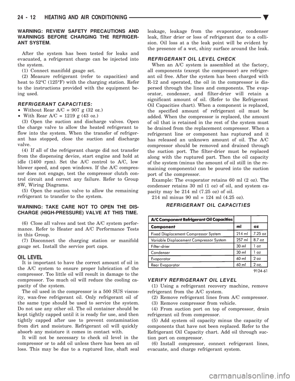
port of the compressor. Example: The evaporator retains 60 ml (2 oz). The
condenser retains 30 ml (1 oz) of oil, and system ca-
pacity may be 214 ml (7.25 oz) of oil. 214 ml minus 90 ml = 124 ml (4.25 oz).
VERIFY REFRIGERANT OIL LEVEL
(1) Using a refrigerant recovery machine, remove
refrigerant from the A/C system. (2) Remove refrigerant lines from A/C compressor.
(3) Remove compressor from vehicle.
(4) From suction port on top of compressor, drain
refrigerant oil from compressor. (5) Add system oil capacity minus the capacity of
components that have not been replaced. Refer to the
Refrigerant Oil Capacity chart. Add oil through suc-
tion port on compressor. (6) Install compressor, connect refrigerant lines,
evacuate, and charge refrigerant system.
REFRIGERANT OIL CAPACITIES
24 - 12 HEATING AND AIR CONDITIONING Ä
Page 2317 of 2438
VARIABLE DISPLACEMENT COMPRESSORÐMODEL 6C17 INDEX
page page
Clutch Coil Tests ......................... 17
Compressor ............................. 17
Compressor Clutch Inoperative .............. 13
Compressor Clutch/Coil Assembly ............ 19
Compressor Diagnosis ..................... 13
Compressor Front Shaft Seal ............... 20 Compressor High Pressure Cut-Out Switch
..... 21
Compressor High Pressure Relief Valve (HPR) . . 22
Compressor Identification ................... 13
Compressor Main or Sub Control Valves ....... 22
Compressor Noise ........................ 13
General Information ....................... 13
GENERAL INFORMATION
The Variable Displacement Compressor (VDC) pro-
vides maximum A/C performance under most condi-
tions. It is designed to operate continuously without
any cycling of the compressor clutch. The compressor
has a variable angle wobble plate with six axially
oriented cylinders. During vehicle A/C system operation, the compres-
sor will change its displacement to match the vehi-
cles A/C cooling demands. When the A/C system
needs more cooling capacity, the compressor will in-
crease its pumping capacity. This is done by increas-
ing the wobble plate angle to increase the piston
stroke. When the A/C system cooling demand is low,
the compressor will decrease its pumping capacity by
reducing the piston pumping stroke. The low cooling
capacity will prevent evaporator from freezing.
COMPRESSOR IDENTIFICATION
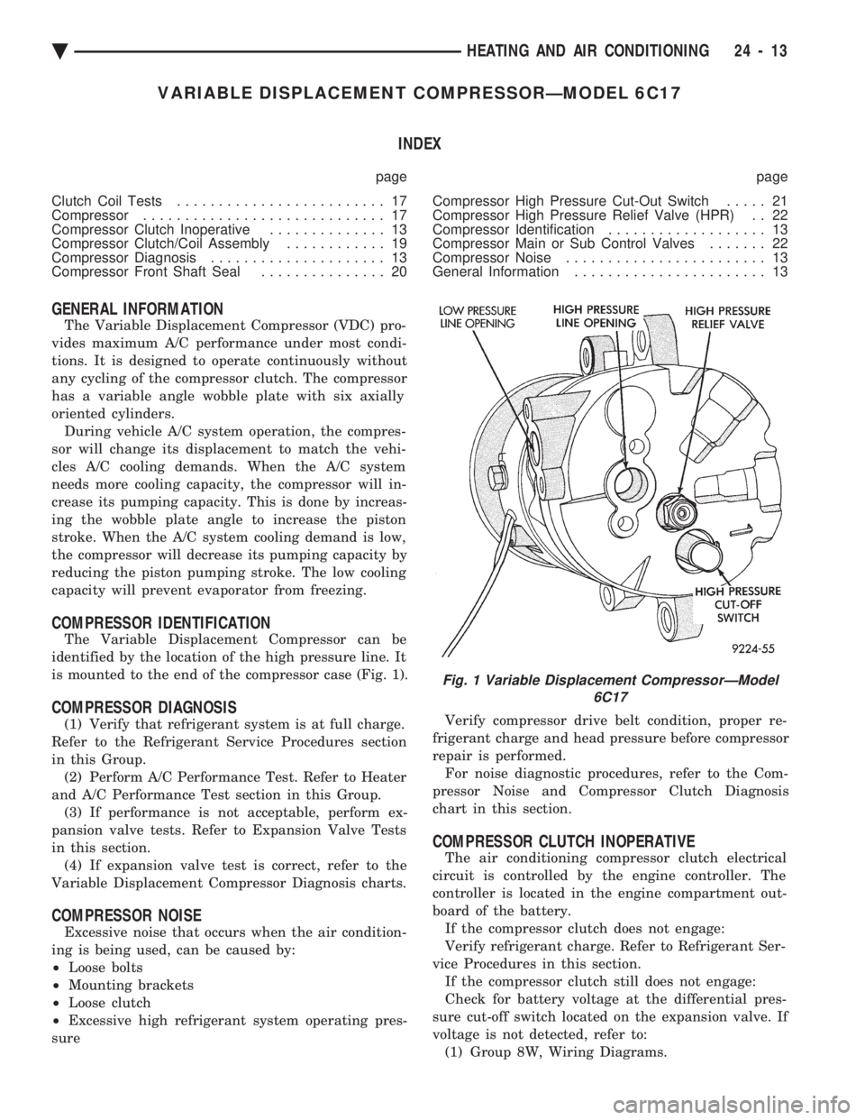
The Variable Displacement Compressor can be
identified by the location of the high pressure line. It
is mounted to the end of the compressor case (Fig. 1).
COMPRESSOR DIAGNOSIS
(1) Verify that refrigerant system is at full charge.
Refer to the Refrigerant Service Procedures section
in this Group. (2) Perform A/C Performance Test. Refer to Heater
and A/C Performance Test section in this Group. (3) If performance is not acceptable, perform ex-
pansion valve tests. Refer to Expansion Valve Tests
in this section. (4) If expansion valve test is correct, refer to the
Variable Displacement Compressor Diagnosis charts.
COMPRESSOR NOISE
Excessive noise that occurs when the air condition-
ing is being used, can be caused by:
² Loose bolts
² Mounting brackets
² Loose clutch
² Excessive high refrigerant system operating pres-
sure Verify compressor drive belt condition, proper re-
frigerant charge and head pressure before compressor
repair is performed. For noise diagnostic procedures, refer to the Com-
pressor Noise and Compressor Clutch Diagnosis
chart in this section.
COMPRESSOR CLUTCH INOPERATIVE
The air conditioning compressor clutch electrical
circuit is controlled by the engine controller. The
controller is located in the engine compartment out-
board of the battery. If the compressor clutch does not engage:
Verify refrigerant charge. Refer to Refrigerant Ser-
vice Procedures in this section. If the compressor clutch still does not engage:
Check for battery voltage at the differential pres-
sure cut-off switch located on the expansion valve. If
voltage is not detected, refer to: (1) Group 8W, Wiring Diagrams.
Fig. 1 Variable Displacement CompressorÐModel 6C17
Ä HEATING AND AIR CONDITIONING 24 - 13