1993 CHEVROLET PLYMOUTH ACCLAIM instrument panel
[x] Cancel search: instrument panelPage 296 of 2438

HYDRAULIC SYSTEM CONTROL VALVES INDEX
page page
General Information ....................... 10
Hydraulic System Service Procedures ......... 11 Pressure Differential Warning Light Switch
...... 10
GENERAL INFORMATION
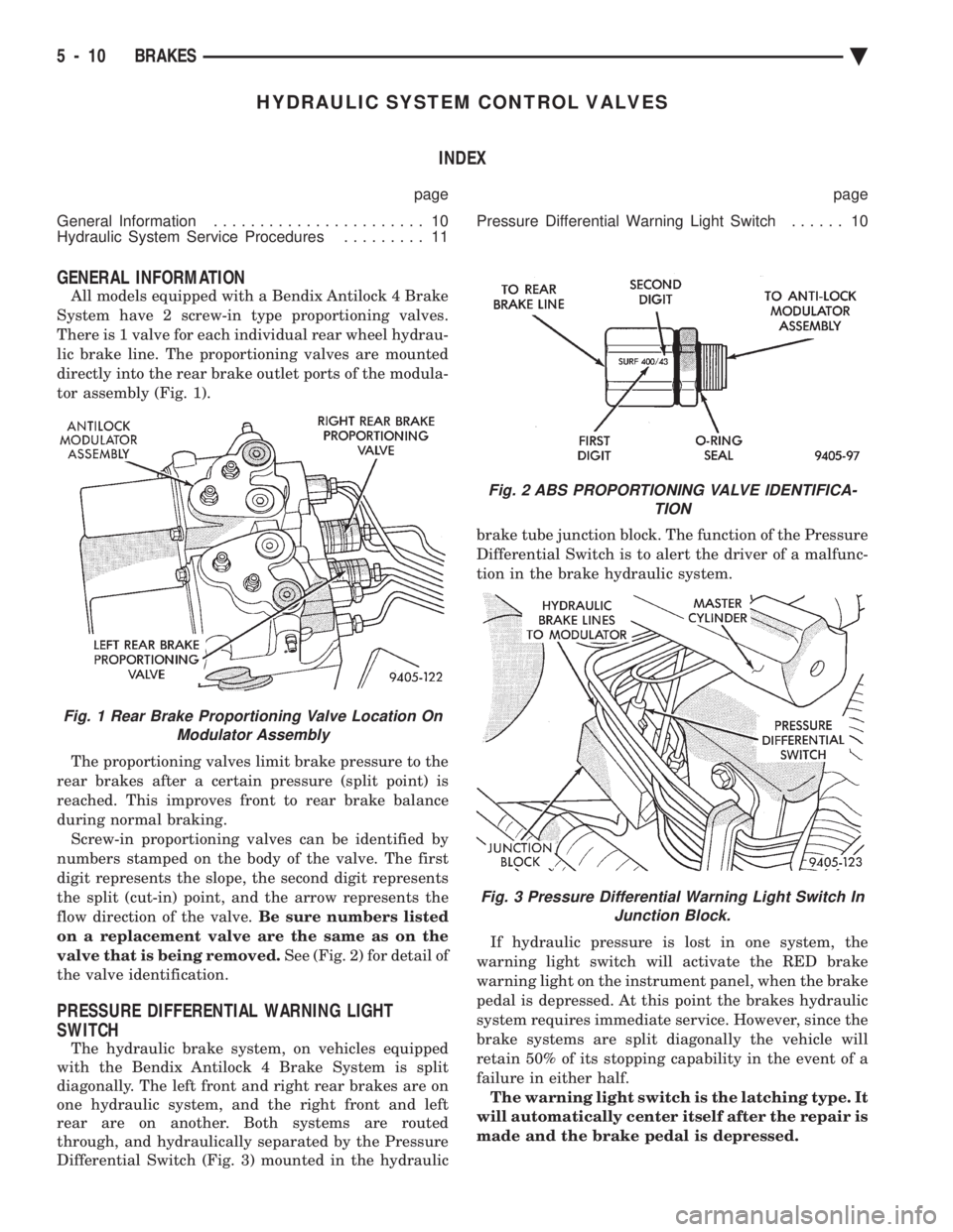
All models equipped with a Bendix Antilock 4 Brake
System have 2 screw-in type proportioning valves.
There is 1 valve for each individual rear wheel hydrau-
lic brake line. The proportioning valves are mounted
directly into the rear brake outlet ports of the modula-
tor assembly (Fig. 1).
The proportioning valves limit brake pressure to the
rear brakes after a certain pressure (split point) is
reached. This improves front to rear brake balance
during normal braking. Screw-in proportioning valves can be identified by
numbers stamped on the body of the valve. The first
digit represents the slope, the second digit represents
the split (cut-in) point, and the arrow represents the
flow direction of the valve. Be sure numbers listed
on a replacement valve are the same as on the
valve that is being removed. See (Fig. 2) for detail of
the valve identification.
PRESSURE DIFFERENTIAL WARNING LIGHT
SWITCH
The hydraulic brake system, on vehicles equipped
with the Bendix Antilock 4 Brake System is split
diagonally. The left front and right rear brakes are on
one hydraulic system, and the right front and left
rear are on another. Both systems are routed
through, and hydraulically separated by the Pressure
Differential Switch (Fig. 3) mounted in the hydraulic brake tube junction block. The function of the Pressure
Differential Switch is to alert the driver of a malfunc-
tion in the brake hydraulic system.
If hydraulic pressure is lost in one system, the
warning light switch will activate the RED brake
warning light on the instrument panel, when the brake
pedal is depressed. At this point the brakes hydraulic
system requires immediate service. However, since the
brake systems are split diagonally the vehicle will
retain 50% of its stopping capability in the event of a
failure in either half. The warning light switch is the latching type. It
will automatically center itself after the repair is
made and the brake pedal is depressed.
Fig. 1 Rear Brake Proportioning Valve Location On Modulator Assembly
Fig. 2 ABS PROPORTIONING VALVE IDENTIFICA- TION
Fig. 3 Pressure Differential Warning Light Switch InJunction Block.
5 - 10 BRAKES Ä
Page 297 of 2438

The instrument panel bulb can be checked each
time the ignition switch is turned to the start posi-
tion or the parking brake is set.
HYDRAULIC SYSTEM SERVICE PROCEDURES
BRAKE WARNING SYSTEM
CHECKING BRAKE WARNING SWITCH UNIT
The Red Brake Warning light will come on when the
parking brake is applied with the ignition key turned
ON. The same light will also illuminate should one of
the two service brake hydraulic systems fail.
CAUTION:Make sure air does not enter the hydraulic
system during this test procedure. See bleeding with-
out a pressure bleeder at the beginning of this section
for master cylinder fluid level checking procedures.
To test the service brake warning system lamp.
Raise vehicle on a hoist and open a wheel cylinder
bleeder while a helper depresses the brake pedal and
observes the warning light.
If light fails to come on, inspect for a burned out bulb,
disconnected socket, or a broken or disconnected wire at
the switch. If the bulb is not burned out and the wire
continuity is not interrupted. Check the service brake
warning switch operation with a test lamp between the
switch terminal and a known good ground. Be sure to
fill master cylinder and bleed brake system after correc-
tion has been made, if necessary.
TESTING ANTILOCK PROPORTIONING VALVES
(1) Install one gauge and (TEE) between modula-
tor assembly and male end (Inlet) of proportioning
valve (Fig. 4). (2) Install second gauge at female end (Outlet) of
proportioning valve (Fig. 4).
(3) Have a helper exert pressure on brake pedal to
obtain and hold required pressure reading on the
valve inlet gauge. (4) Check reading on outlet gauge. If inlet and out-
let pressures do not agree with the following chart,
replace the valve. See (Fig. 3) for proportioning valve
identification.
BENDIX ANTILOCK 4 PROPORTIONING VALVE APPLICATIONS
BENDIX ANTILOCK 4 PROPORTIONING VALVE PRESSURES
Fig. 4 Tube Connections for ABS
Ä BRAKES 5 - 11
Page 303 of 2438

fice (restriction) in the line between the wheel and
the Build/Decay Valve. This restriction provides a
controlled build rate to each wheel brake during an
Antilock stop. The Shuttle Orifice Valve will remain
in the orificed position until the ABS cycle is com-
plete. When the ABS cycle has been completed the
Build/Decay valves will return to their released posi-
tion which will equalize the pressure across the
Shuttle Orifice Valves. When the pressure equalizes,
the spring loaded Shuttle Orifice valves will return
to the unrestricted position.
FLUID SUMPS
There are two Fluid Sumps in the Hydraulic As-
sembly, one for the primary and secondary hydraulic
circuits. The Fluid Sumps store the brake fluid that
is decayed from the wheel brakes during an ABS cy-
cle. This fluid is then pumped to an accumulator
and/or the hydraulic system in order to provide build
pressure. The typical pressure in the sumps is 50 psi,
during ABS operation only.
HYDRAULIC SPRING ACCUMULATOR
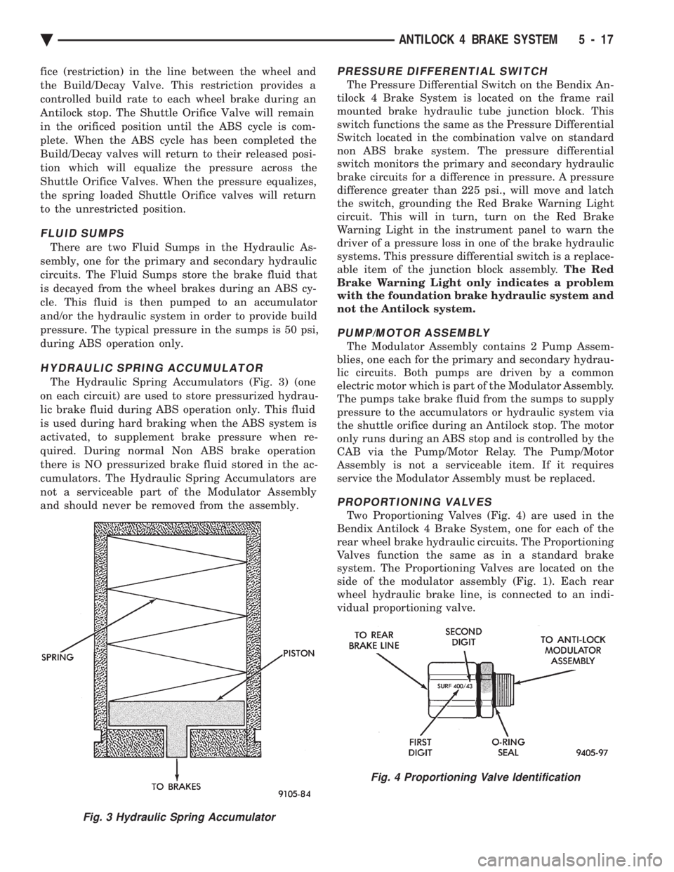
The Hydraulic Spring Accumulators (Fig. 3) (one
on each circuit) are used to store pressurized hydrau-
lic brake fluid during ABS operation only. This fluid
is used during hard braking when the ABS system is
activated, to supplement brake pressure when re-
quired. During normal Non ABS brake operation
there is NO pressurized brake fluid stored in the ac-
cumulators. The Hydraulic Spring Accumulators are
not a serviceable part of the Modulator Assembly
and should never be removed from the assembly.
PRESSURE DIFFERENTIAL SWITCH
The Pressure Differential Switch on the Bendix An-
tilock 4 Brake System is located on the frame rail
mounted brake hydraulic tube junction block. This
switch functions the same as the Pressure Differential
Switch located in the combination valve on standard
non ABS brake system. The pressure differential
switch monitors the primary and secondary hydraulic
brake circuits for a difference in pressure. A pressure
difference greater than 225 psi., will move and latch
the switch, grounding the Red Brake Warning Light
circuit. This will in turn, turn on the Red Brake
Warning Light in the instrument panel to warn the
driver of a pressure loss in one of the brake hydraulic
systems. This pressure differential switch is a replace-
able item of the junction block assembly. The Red
Brake Warning Light only indicates a problem
with the foundation brake hydraulic system and
not the Antilock system.
PUMP/MOTOR ASSEMBLY
The Modulator Assembly contains 2 Pump Assem-
blies, one each for the primary and secondary hydrau-
lic circuits. Both pumps are driven by a common
electric motor which is part of the Modulator Assembly.
The pumps take brake fluid from the sumps to supply
pressure to the accumulators or hydraulic system via
the shuttle orifice during an Antilock stop. The motor
only runs during an ABS stop and is controlled by the
CAB via the Pump/Motor Relay. The Pump/Motor
Assembly is not a serviceable item. If it requires
service the Modulator Assembly must be replaced.
PROPORTIONING VALVES
Two Proportioning Valves (Fig. 4) are used in the
Bendix Antilock 4 Brake System, one for each of the
rear wheel brake hydraulic circuits. The Proportioning
Valves function the same as in a standard brake
system. The Proportioning Valves are located on the
side of the modulator assembly (Fig. 1). Each rear
wheel hydraulic brake line, is connected to an indi-
vidual proportioning valve.
Fig. 3 Hydraulic Spring Accumulator
Fig. 4 Proportioning Valve Identification
Ä ANTILOCK 4 BRAKE SYSTEM 5 - 17
Page 305 of 2438

(4) Provide communication to the DRB II while in
the Antilock brakes diagnostic mode. The CAB continuously monitors the speed of each
wheel, through the signals generated at the Wheel
Speed Sensors. This is used to determine if any
wheel of the vehicle is beginning to lock-up (skid)
when the brakes are applied. When a wheel locking
tendency is detected during brake apply. The CAB
commands the appropriate Build/Decay valves to
modulate brake fluid pressure in some or all of the
hydraulic circuits. The CAB continues to control
pressure in individual hydraulic circuits until a lock-
ing tendency is no longer present. The ABS system is constantly monitored by the
CAB for proper operation. If the CAB detects a fault,
it will turn on the Amber Antilock Warning Lamp
and disable the ABS brake system. The normal Non
ABS brake system will remain operational. The CAB contains a self-diagnostic program which
will turn on the Amber Antilock Warning Lamp
when a system fault is detected. Faults are stored in
a diagnostic program memory. There are 16 fault
codes which may be stored in the CAB and displayed
through the DRB II. These fault codes will remain in
the CAB memory even after the ignition has been
turned off. The fault codes can be cleared by using
the DRB II diagnostics tester, or they will be auto-
matically cleared from the memory after (50) ignition
switch on/off cycles.
CONTROLLER ANTILOCK BRAKE (INPUTS)
² Four wheel speed sensors.
² Stop lamp switch.
² Ignition switch.
² System relay voltage.
² Ground.
² Pump/Motor Relay Monitor
² Diagnostics Communications
CONTROLLER ANTILOCK BRAKE (OUTPUTS)
²4 Build/Decay valves.
² Antilock warning lamp.
² System relay actuation.
² Diagnostic communication.
² Pump/Motor relay actuation
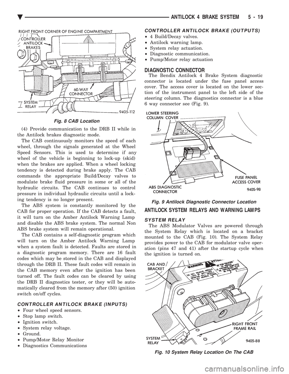
DIAGNOSTIC CONNECTOR
The Bendix Antilock 4 Brake System diagnostic
connector is located under the fuse panel access
cover. The access cover is located on the lower sec-
tion of the instrument panel to the left side of the
steering column. The diagnostics connector is a blue
6 way connector see (Fig. 9).
ANTILOCK SYSTEM RELAYS AND WARNING LAMPS
SYSTEM RELAY
The ABS Modulator Valves are powered through
the System Relay which is located on a bracket
mounted to the CAB (Fig. 10). The System Relay
provides power to the CAB for modulator valve oper-
ation (pins 47 and 41) after the startup cycle when
the ignition is turned on.
Fig. 8 CAB Location
Fig. 9 Antilock Diagnostic Connector Location
Fig. 10 System Relay Location On The CAB
Ä ANTILOCK 4 BRAKE SYSTEM 5 - 19
Page 336 of 2438

CLUTCH PEDAL POSITION SWITCH
The clutch pedal position switch functions as a
safety interlock device. It prevents possible engine
cranking with the clutch engaged. The clutch pedal position switch is wired in series
between the starter relay coil and the ignition
switch. The clutch pedal position switch is mounted to a
bracket located next to the clutch pedal. The switch
is held in place by four plastic wing tabs. The clutch pedal position switch has an adjustable
striker plate. The striker plate is located on the left
side of the clutch pedal (Fig. 3).
DIAGNOSIS
Disconnect clutch pedal position switch harness
from instrument panel wiring harness. Using a ohm
meter, check for continuity between the two termi-
nals in the connector on the switch harness. There
should be no continuity between the terminals when
the switch is in its neutral (fully extended) position.
When the switch is depressed more than 1.25 mm
(0.050) the ohm meter should show continuity. If all ohm meter readings are correct and the
switch does not operate correctly, adjustment is re-
quired. Refer to Switch Adjustment Procedure to ad-
just switch.
REMOVAL
(1) Disconnect electrical harness to switch connec-
tor. (2) Depress wing tabs on switch and push switch out
of mounting bracket. Then slide wires through slot in
bracket.
INSTALLATION
(1) Slide switch wires through slot in switch bracket.
(2) Line up switch tab with slot in switch bracket
and push switch into position. Do not pull on the switch
wires to seat switch into bracket, switch damage may
occur. (3) After installation, the switch must be adjusted
and checked for proper operation. Refer to Switch
Adjustment Procedure.
ADJUSTMENT PROCEDURE
When performing switch adjustment, the floor mat
should be removed before beginning adjustment proce-
dures. (1) Set the park brake.
(2) Disconnect clutch cable at the transaxle end of
the cable. (3) Depress clutch pedal, loosen adjusting nut and
slide the striker plate forward to fully compress the
clutch pedal position switch plunger. (4) Tighten adjusting nut to 12 N Im (105 in. lbs.).
(5) Reconnect clutch cable.
The clutch pedal position switch is now ad-
justed. A final check is required to insure that the
switch is ``made'' below the clutch release point. (1) With the park brake set and the vehicle IN
NEUTRAL turn the key to the start position. The
vehicle should not crank. If the vehicle cranks do
not continue with this test. Recheck the switch and
switch adjustment to determine the cause. If the ve-
hicle does not crank proceed to step 2. (2) With the park brake set and the vehicle IN
GEAR turn the key to the start position.
WARNING: BEFORE PERFORMING STEP THREE BE
SURE THAT THE AREA IN FRONT OF THE VEHICLE
IS CLEAR OF OBSTRUCTIONS AND PEOPLE. VE-
HICLE MAY MOVE WHEN PERFORMING THIS TEST.
(3) Slowly depress the clutch pedal and feel for any
vehicle motion when the starter is energized. If there is
no motion the switch is properly adjusted. If motion is
felt, repeat the adjustment procedure.
Fig. 3 Clutch Pedal Position Switch and Components
6 - 4 MANUAL TRANSAXLE CLUTCH Ä
Page 430 of 2438

dition exists. These messages are displayed on the
center of the instrument panel.For complete EVIC operating instructions, refer to
the Owners Manual provided with the vehicle.
EVIC BUTTON FUNCTIONS
TIME button will display:
² Time of day
² Day of week
² Day of month
² Month of year
² To set HOURS, press TIME button and within four
seconds press the SET button. An arrow will appear
on the display and point to the hours. Press and hold
the SET button to advance the hours or INFO button
to set back the hours.
² To set MINUTES, press TIME button. The arrow
will point to the minutes. Press and hold the SET
button to advance the minutes or INFO button to set
back the minutes.
² To set DAY of WEEK, press TIME button. An ar-
row will appear on the display and point to the Day.
Press and hold the SET button to move the day for-
ward or INFO button to move it backward.
² To set DAY of MONTH, press TIME button. The
arrow will point to Date. Press and hold the SET
button to advance the date or INFO button to move
it backwards.
² To set MONTH of YEAR, press TIME button. The
arrow will point to the Month. Press and hold the
SET button to advance the Month forward or INFO
button to move backward. TEMP button, pressing the Temp button will dis-
play:
² The temperature outside the vehicle
² Vehicle direction define by an eight point compass
If Compass has lost calibration or not receiving
good information from the engine compartment node,
an asterisk (*) will flash on the display and the word
calibrate will appear. Refer to Compass Calibration. FUEL BUTTON, WILL DISPLAY:
² Pressing FUEL button the first time will show, the
estimated number of miles that can be driven with
the remaining fuel. The destination to empty indica-
tion will vary every few seconds as the amount of
fuel and fuel efficiency is calculated. This function
can not be reset.
² Pressing the FUEL button second time; will dis-
play the fuel consumed.
² Pressing the FUEL button third time; will display
the average fuel economy in miles per gallon since
last reset. The display will be updated every 16 sec-
onds.
² Pressing the FUEL button forth time, the current
fuel economy will be displayed. The current fuel
economy will be up updated every two seconds. ²
To reset Fuel consumed, press SET button until
the fuel consumed message is displayed and then
within five seconds press SET button.
² To reset AVERAGE FUEL ECONOMY, press the
FUEL button until average fuel economy is displayed
and within five seconds press SET button. TRIP RESET, press FUEL button and wait four
seconds press the SET button twice. This clears all
trip information and the message Trip Reset will be
displayed. This will occur only if a reset function is
currently being displayed. The reset functions:
² Fuel consumed
² Average fuel economy message
INFO button, will active a MONITORED SYS-
TEMS OK message on display if all monitored sys-
tems are operating properly. If a problem is detected,
the appropriate message will be displayed. SET button, will clear the various functions after
they have been displayed. It is used to enter the
clock set or compass variance modes. This button is
also used to reset certain trip computer functions and
the maintenance reminder message. The EVIC display may be turned off by pressing
the TIME and SET buttons at the same time. Press-
ing the buttons a second time will restore the dis-
play.
EVIC INFORMATION SOURCES
The EVIC monitors information provided by the
body controller, engine compartment node and pow-
ertrain control module. Refer to Body Diagnostic Test
Procedure Manual for test procedures. The Body Controller is a micro-controller unit
which, informs the EVIC via the CCD bus of:
² Time of day
² Day of week
² Day of month
² Month of year
² Fuel range
² Fuel consumed
² Fuel efficiency
² Warning messages as noted in Fig. 3.
The Engine Compartment Node is a microcomputer
controlled unit which, informs the EVIC via the CCD
bus of:
² Outside temperature
² Compass direction
THE FOLLOWING ARE WARNING MESSAGES:
² Low brake fluid
² Low coolant level
² Low engine oil level
The powertrain control module is a microcomputer
controlled unit which, informs the EVIC via the CCD
bus of the following warning messages:
² Engine temperature high
² Voltage improper
8C - 14 OVERHEAD CONSOLE Ä
Page 458 of 2438

(3) Inspect the spark plug condition. Refer to Spark
Plug Condition in this section.
SPARK PLUG GAP ADJUSTMENT
Check the spark plug gap with a gap gauge. If the
gap is not correct, adjust it by bending the ground
electrode (Fig. 6).
SPARK PLUG INSTALLATION
(1) Start the spark plug into the cylinder head by
hand to avoid cross threading. (2) Tighten spark plugs to 28 N Im (20 ft. lbs.)
torque. (3) Install spark plug cables over spark plugs.
IDLE RPM TESTÐ2.5L AND 3.0L ENGINES
WARNING: APPLY PARKING BRAKE AND/OR BLOCK
WHEELS BEFORE PERFORMING IDLE CHECK OR
ADJUSTMENT, OR ANY TESTS WITH A RUNNING
ENGINE.
Engine idle set rpmshould be recorded when the
vehicle is first brought into shop for testing. This
will assist in diagnosing complaints of engine stalling,
creeping and hard shifting on vehicles equipped with
automatic transaxles. Proceed to the Throttle Body Minimum Airflow pro-
cedures in Group 14.
IGNITION TIMING PROCEDUREÐ2.2L TBI, 2.5L
TBI, 2.5L MPI, AND 3.0L ENGINES
WARNING: APPLY PARKING BRAKE AND/OR BLOCK
WHEELS BEFORE PERFORMING SETTING IGNITION
TIMING OR PERFORMING ANY TEST ON AN OPER-
ATING ENGINE.
Proper ignition timing is required to obtain optimum
engine performance. The distributor must be correctly
indexed to provide correct initial ignition timing. (1) Set the gearshift selector in park or neutral and
apply the parking brake. All lights and accessories
must be off. (2) If using a magnetic timing light, insert the
pickup probe into the open receptacle next to the
timing scale window. If a magnetic timing unit is not
available, use a conventional timing light connected to
the number one cylinder spark plug cable. Do not puncture cables, boots or nipples with
test probes. Always use proper adapters. Punc-
turing the spark plug cables with a probe will
damage the cables. The probe can separate the
conductor and cause high resistance. In addition
breaking the rubber insulation may permit sec-
ondary current to arc to ground. (3) Turn selector switch to the appropriate cylinder
position. (4) Start engine and run until operating tempera-
ture is obtained. (5) With the engine at normal operating tempera-
ture, connect the DRBII scan tool to the data link
connector (diagnostic connector). Access the State Dis-
play screen. Refer to the appropriate Powertrain Diag-
nostics Procedures Manual. If not using the DRBII
scan tool, disconnect the coolant temperature
sensor electrical connector. The electric radiator
fan will operate and the malfunction indicator lamp
(instrument panel Check Engine light) will turn on
after disconnecting the coolant sensor or starting the
DRBII scan tool procedure. (6) Aim Timing Light at timing scale (Fig. 7 or Fig.
8) or read magnetic timing unit. If flash occurs when
timing mark is before specified degree mark, timing is
advanced. To adjust, turn distributor housing in direc-
tion of rotor rotation. If flash occurs when timing mark is after specified
degree mark, timing is retarded. To adjust, turn dis-
tributor housing against direction of rotor rotation.
Refer to Vehicle Emission Control Information label for
correct timing specification. If timing is within 62É of
value specified on the label, proceed to step (8). If
outside specified tolerance, proceed to next step. (7) Loosen distributor hold-down arm screw
enough to rotate the distributor housing (Fig. 9 or
Fig. 6 Setting Spark Plug GapÐTypical
8D - 16 IGNITION SYSTEMS Ä
Page 493 of 2438

INSTRUMENT PANEL AND GAUGES
CONTENTS
page page
AA BODY .............................. 1
AC AND AY BODIES .................... 23 AG AND AJ BODIES
.................... 42
AP BODY ............................. 58
AA BODY INDEX
page page
Cluster and Gauge Service and Testing ........ 2
Electronic Cluster ........................ 13
Fuel GaugeÐFlexible Fuel .................. 2
Gauges ................................. 7
General Information ........................ 1 Instrument Panel
......................... 21
Interior Lamp Replacement ................. 21
Mechanical/Electronic Cluster Removal ......... 5
Switch and Panel Component Service ......... 15
GENERAL INFORMATION
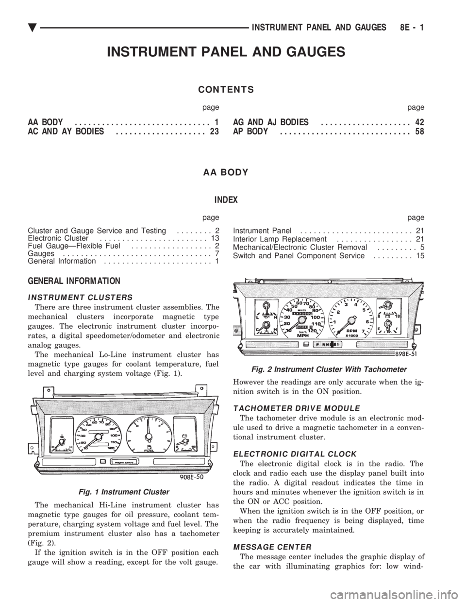
INSTRUMENT CLUSTERS
There are three instrument cluster assemblies. The
mechanical clusters incorporate magnetic type
gauges. The electronic instrument cluster incorpo-
rates, a digital speedometer/odometer and electronic
analog gauges. The mechanical Lo-Line instrument cluster has
magnetic type gauges for coolant temperature, fuel
level and charging system voltage (Fig. 1).
The mechanical Hi-Line instrument cluster has
magnetic type gauges for oil pressure, coolant tem-
perature, charging system voltage and fuel level. The
premium instrument cluster also has a tachometer
(Fig. 2). If the ignition switch is in the OFF position each
gauge will show a reading, except for the volt gauge. However the readings are only accurate when the ig-
nition switch is in the ON position.
TACHOMETER DRIVE MODULE
The tachometer drive module is an electronic mod-
ule used to drive a magnetic tachometer in a conven-
tional instrument cluster.
ELECTRONIC DIGITAL CLOCK
The electronic digital clock is in the radio. The
clock and radio each use the display panel built into
the radio. A digital readout indicates the time in
hours and minutes whenever the ignition switch is in
the ON or ACC position. When the ignition switch is in the OFF position, or
when the radio frequency is being displayed, time
keeping is accurately maintained.
MESSAGE CENTER
The message center includes the graphic display of
the car with illuminating graphics for: low wind-
Fig. 1 Instrument Cluster
Fig. 2 Instrument Cluster With Tachometer
Ä INSTRUMENT PANEL AND GAUGES 8E - 1