1993 CHEVROLET PLYMOUTH ACCLAIM instrument panel
[x] Cancel search: instrument panelPage 2371 of 2438
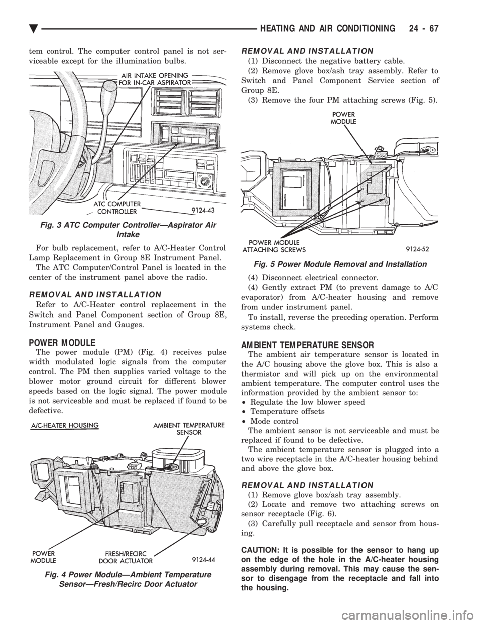
tem control. The computer control panel is not ser-
viceable except for the illumination bulbs. For bulb replacement, refer to A/C-Heater Control
Lamp Replacement in Group 8E Instrument Panel. The ATC Computer/Control Panel is located in the
center of the instrument panel above the radio.
REMOVAL AND INSTALLATION
Refer to A/C-Heater control replacement in the
Switch and Panel Component section of Group 8E,
Instrument Panel and Gauges.
POWER MODULE
The power module (PM) (Fig. 4) receives pulse
width modulated logic signals from the computer
control. The PM then supplies varied voltage to the
blower motor ground circuit for different blower
speeds based on the logic signal. The power module
is not serviceable and must be replaced if found to be
defective.
REMOVAL AND INSTALLATION
(1) Disconnect the negative battery cable.
(2) Remove glove box/ash tray assembly. Refer to
Switch and Panel Component Service section of
Group 8E. (3) Remove the four PM attaching screws (Fig. 5).
(4) Disconnect electrical connector.
(4) Gently extract PM (to prevent damage to A/C
evaporator) from A/C-heater housing and remove
from under instrument panel. To install, reverse the preceding operation. Perform
systems check.
AMBIENT TEMPERATURE SENSOR
The ambient air temperature sensor is located in
the A/C housing above the glove box. This is also a
thermistor and will pick up on the environmental
ambient temperature. The computer control uses the
information provided by the ambient sensor to:
² Regulate the low blower speed
² Temperature offsets
² Mode control
The ambient sensor is not serviceable and must be
replaced if found to be defective. The ambient temperature sensor is plugged into a
two wire receptacle in the A/C-heater housing behind
and above the glove box.
REMOVAL AND INSTALLATION
(1) Remove glove box/ash tray assembly.
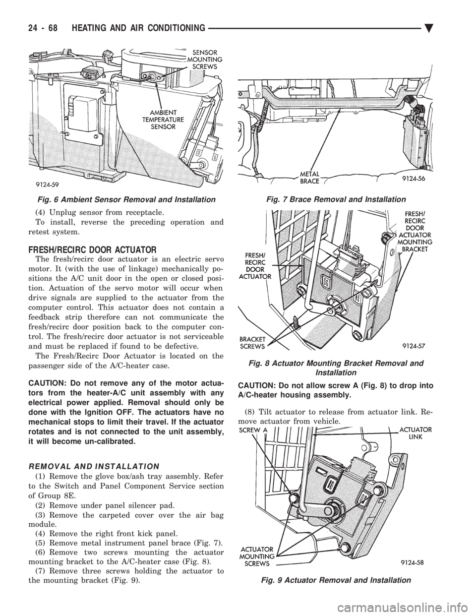
(2) Locate and remove two attaching screws on
sensor receptacle (Fig. 6). (3) Carefully pull receptacle and sensor from hous-
ing.
CAUTION: It is possible for the sensor to hang up
on the edge of the hole in the A/C-heater housing
assembly during removal. This may cause the sen-
sor to disengage from the receptacle and fall into
the housing.
Fig. 3 ATC Computer ControllerÐAspirator Air Intake
Fig. 4 Power ModuleÐAmbient TemperatureSensorÐFresh/Recirc Door Actuator
Fig. 5 Power Module Removal and Installation
Ä HEATING AND AIR CONDITIONING 24 - 67
Page 2372 of 2438
(4) Unplug sensor from receptacle.
To install, reverse the preceding operation and
retest system.
FRESH/RECIRC DOOR ACTUATOR
The fresh/recirc door actuator is an electric servo
motor. It (with the use of linkage) mechanically po-
sitions the A/C unit door in the open or closed posi-
tion. Actuation of the servo motor will occur when
drive signals are supplied to the actuator from the
computer control. This actuator does not contain a
feedback strip therefore can not communicate the
fresh/recirc door position back to the computer con-
trol. The fresh/recirc door actuator is not serviceable
and must be replaced if found to be defective. The Fresh/Recirc Door Actuator is located on the
passenger side of the A/C-heater case.
CAUTION: Do not remove any of the motor actua-
tors from the heater-A/C unit assembly with any
electrical power applied. Removal should only be
done with the Ignition OFF. The actuators have no
mechanical stops to limit their travel. If the actuator
rotates and is not connected to the unit assembly,
it will become un-calibrated.
REMOVAL AND INSTALLATION
(1) Remove the glove box/ash tray assembly. Refer
to the Switch and Panel Component Service section
of Group 8E. (2) Remove under panel silencer pad.
(3) Remove the carpeted cover over the air bag
module. (4) Remove the right front kick panel.
(5) Remove metal instrument panel brace (Fig. 7).
(6) Remove two screws mounting the actuator
mounting bracket to the A/C-heater case (Fig. 8). (7) Remove three screws holding the actuator to
the mounting bracket (Fig. 9). CAUTION: Do not allow screw A (Fig. 8) to drop into
A/C-heater housing assembly.
(8) Tilt actuator to release from actuator link. Re-
move actuator from vehicle.
Fig. 9 Actuator Removal and Installation
Fig. 6 Ambient Sensor Removal and InstallationFig. 7 Brace Removal and Installation
Fig. 8 Actuator Mounting Bracket Removal and Installation
24 - 68 HEATING AND AIR CONDITIONING Ä
Page 2374 of 2438
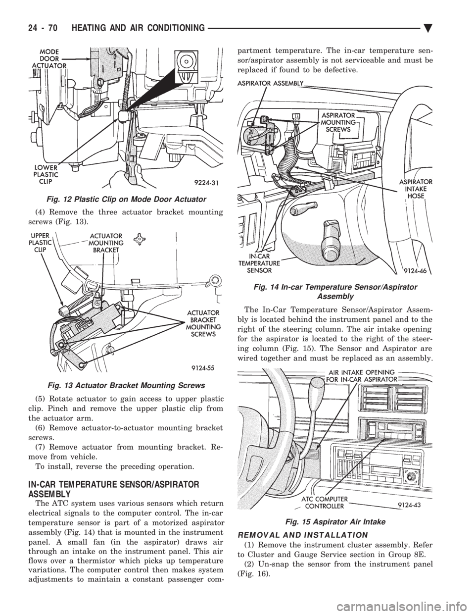
(4) Remove the three actuator bracket mounting
screws (Fig. 13).
(5) Rotate actuator to gain access to upper plastic
clip. Pinch and remove the upper plastic clip from
the actuator arm. (6) Remove actuator-to-actuator mounting bracket
screws. (7) Remove actuator from mounting bracket. Re-
move from vehicle. To install, reverse the preceding operation.
IN-CAR TEMPERATURE SENSOR/ASPIRATOR
ASSEMBLY
The ATC system uses various sensors which return
electrical signals to the computer control. The in-car
temperature sensor is part of a motorized aspirator
assembly (Fig. 14) that is mounted in the instrument
panel. A small fan (in the aspirator) draws air
through an intake on the instrument panel. This air
flows over a thermistor which picks up temperature
variations. The computer control then makes system
adjustments to maintain a constant passenger com- partment temperature. The in-car temperature sen-
sor/aspirator assembly is not serviceable and must be
replaced if found to be defective.
The In-Car Temperature Sensor/Aspirator Assem-
bly is located behind the instrument panel and to the
right of the steering column. The air intake opening
for the aspirator is located to the right of the steer-
ing column (Fig. 15). The Sensor and Aspirator are
wired together and must be replaced as an assembly.
REMOVAL AND INSTALLATION
(1) Remove the instrument cluster assembly. Refer
to Cluster and Gauge Service section in Group 8E. (2) Un-snap the sensor from the instrument panel
(Fig. 16).
Fig. 12 Plastic Clip on Mode Door Actuator
Fig. 13 Actuator Bracket Mounting Screws
Fig. 14 In-car Temperature Sensor/Aspirator Assembly
Fig. 15 Aspirator Air Intake
24 - 70 HEATING AND AIR CONDITIONING Ä
Page 2375 of 2438
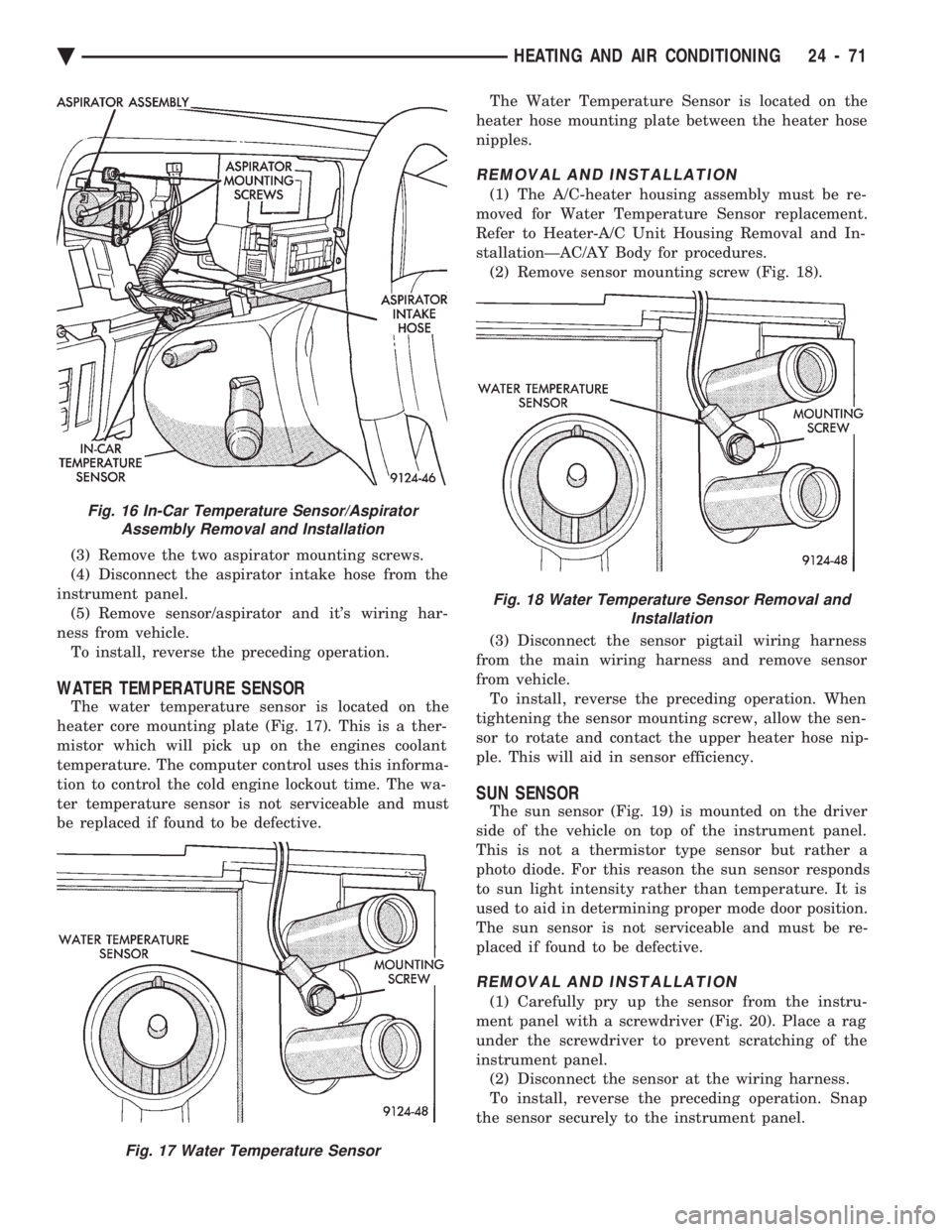
(3) Remove the two aspirator mounting screws.
(4) Disconnect the aspirator intake hose from the
instrument panel. (5) Remove sensor/aspirator and it's wiring har-
ness from vehicle. To install, reverse the preceding operation.
WATER TEMPERATURE SENSOR
The water temperature sensor is located on the
heater core mounting plate (Fig. 17). This is a ther-
mistor which will pick up on the engines coolant
temperature. The computer control uses this informa-
tion to control the cold engine lockout time. The wa-
ter temperature sensor is not serviceable and must
be replaced if found to be defective. The Water Temperature Sensor is located on the
heater hose mounting plate between the heater hose
nipples.
REMOVAL AND INSTALLATION
(1) The A/C-heater housing assembly must be re-
moved for Water Temperature Sensor replacement.
Refer to Heater-A/C Unit Housing Removal and In-
stallationÐAC/AY Body for procedures. (2) Remove sensor mounting screw (Fig. 18).
(3) Disconnect the sensor pigtail wiring harness
from the main wiring harness and remove sensor
from vehicle. To install, reverse the preceding operation. When
tightening the sensor mounting screw, allow the sen-
sor to rotate and contact the upper heater hose nip-
ple. This will aid in sensor efficiency.
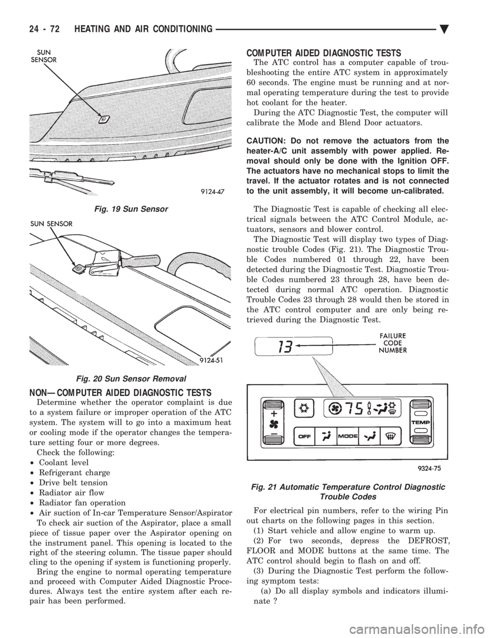
SUN SENSOR
The sun sensor (Fig. 19) is mounted on the driver
side of the vehicle on top of the instrument panel.
This is not a thermistor type sensor but rather a
photo diode. For this reason the sun sensor responds
to sun light intensity rather than temperature. It is
used to aid in determining proper mode door position.
The sun sensor is not serviceable and must be re-
placed if found to be defective.
REMOVAL AND INSTALLATION
(1) Carefully pry up the sensor from the instru-
ment panel with a screwdriver (Fig. 20). Place a rag
under the screwdriver to prevent scratching of the
instrument panel. (2) Disconnect the sensor at the wiring harness.
To install, reverse the preceding operation. Snap
the sensor securely to the instrument panel.
Fig. 16 In-Car Temperature Sensor/Aspirator Assembly Removal and Installation
Fig. 17 Water Temperature Sensor
Fig. 18 Water Temperature Sensor Removal and Installation
Ä HEATING AND AIR CONDITIONING 24 - 71
Page 2376 of 2438
NONÐCOMPUTER AIDED DIAGNOSTIC TESTS
Determine whether the operator complaint is due
to a system failure or improper operation of the ATC
system. The system will to go into a maximum heat
or cooling mode if the operator changes the tempera-
ture setting four or more degrees. Check the following:
² Coolant level
² Refrigerant charge
² Drive belt tension
² Radiator air flow
² Radiator fan operation
² Air suction of In-car Temperature Sensor/Aspirator
To check air suction of the Aspirator, place a small
piece of tissue paper over the Aspirator opening on
the instrument panel. This opening is located to the
right of the steering column. The tissue paper should
cling to the opening if system is functioning properly. Bring the engine to normal operating temperature
and proceed with Computer Aided Diagnostic Proce-
dures. Always test the entire system after each re-
pair has been performed.
COMPUTER AIDED DIAGNOSTIC TESTS
The ATC control has a computer capable of trou-
bleshooting the entire ATC system in approximately
60 seconds. The engine must be running and at nor-
mal operating temperature during the test to provide
hot coolant for the heater. During the ATC Diagnostic Test, the computer will
calibrate the Mode and Blend Door actuators.
CAUTION: Do not remove the actuators from the
heater-A/C unit assembly with power applied. Re-
moval should only be done with the Ignition OFF.
The actuators have no mechanical stops to limit the
travel. If the actuator rotates and is not connected
to the unit assembly, it will become un-calibrated.
The Diagnostic Test is capable of checking all elec-
trical signals between the ATC Control Module, ac-
tuators, sensors and blower control. The Diagnostic Test will display two types of Diag-
nostic trouble Codes (Fig. 21). The Diagnostic Trou-
ble Codes numbered 01 through 22, have been
detected during the Diagnostic Test. Diagnostic Trou-
ble Codes numbered 23 through 28, have been de-
tected during normal ATC operation. Diagnostic
Trouble Codes 23 through 28 would then be stored in
the ATC control computer and are only being re-
trieved during the Diagnostic Test.
For electrical pin numbers, refer to the wiring Pin
out charts on the following pages in this section. (1) Start vehicle and allow engine to warm up.
(2) For two seconds, depress the DEFROST,
FLOOR and MODE buttons at the same time. The
ATC control should begin to flash on and off. (3) During the Diagnostic Test perform the follow-
ing symptom tests: (a) Do all display symbols and indicators illumi-
nate ?
Fig. 19 Sun Sensor
Fig. 20 Sun Sensor Removal
Fig. 21 Automatic Temperature Control Diagnostic Trouble Codes
24 - 72 HEATING AND AIR CONDITIONING Ä
Page 2409 of 2438
These systems do not allow EGR at idle. The 2.2L/
2.5L EGR systems operate at all temperatures. The
3.0L, 3.3L and 3.8L EGR systems do not operate
when coolant temperature is below 4.5ÉC (40É)F at
start-up. These systems activate when coolant tem-
perature reaches 77ÉC (170ÉF).
EGR SYSTEM ON-BOARD DIAGNOSTICS
The powertrain control module (PCM) performs an
on-board diagnostic check of the EGR system on all
California vehicles with EGR systems. The diagnos-
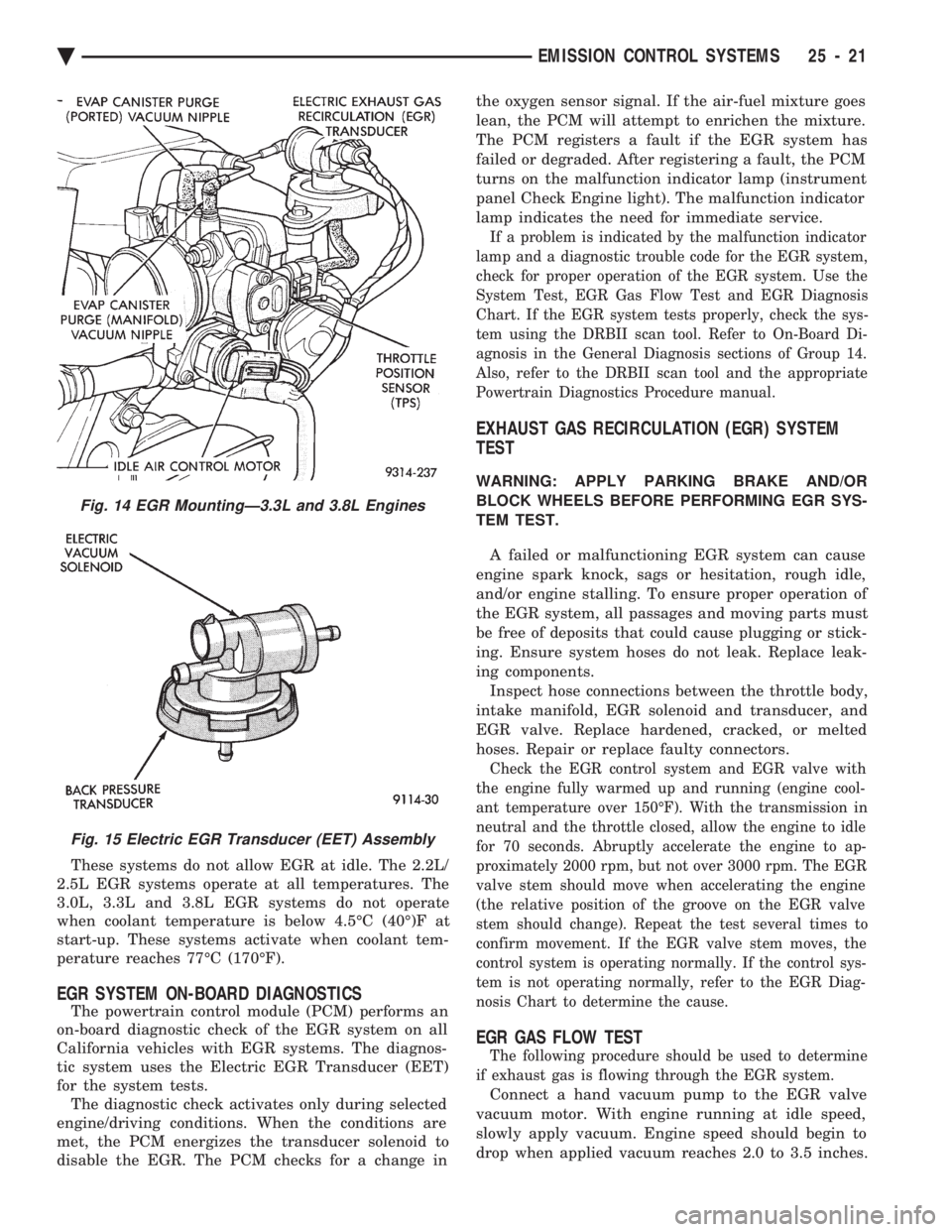
tic system uses the Electric EGR Transducer (EET)
for the system tests. The diagnostic check activates only during selected
engine/driving conditions. When the conditions are
met, the PCM energizes the transducer solenoid to
disable the EGR. The PCM checks for a change in the oxygen sensor signal. If the air-fuel mixture goes
lean, the PCM will attempt to enrichen the mixture.
The PCM registers a fault if the EGR system has
failed or degraded. After registering a fault, the PCM
turns on the malfunction indicator lamp (instrument
panel Check Engine light). The malfunction indicator
lamp indicates the need for immediate service.
If a problem is indicated by the malfunction indicator
lamp and a diagnostic trouble code for the EGR system,
check for proper operation of the EGR system. Use the
System Test, EGR Gas Flow Test and EGR Diagnosis
Chart. If the EGR system tests properly, check the sys-
tem using the DRBII scan tool. Refer to On-Board Di-
agnosis in the General Diagnosis sections of Group 14.
Also, refer to the DRBII scan tool and the appropriate
Powertrain Diagnostics Procedure manual.
EXHAUST GAS RECIRCULATION (EGR) SYSTEM
TEST
WARNING: APPLY PARKING BRAKE AND/OR
BLOCK WHEELS BEFORE PERFORMING EGR SYS-
TEM TEST.
A failed or malfunctioning EGR system can cause
engine spark knock, sags or hesitation, rough idle,
and/or engine stalling. To ensure proper operation of
the EGR system, all passages and moving parts must
be free of deposits that could cause plugging or stick-
ing. Ensure system hoses do not leak. Replace leak-
ing components. Inspect hose connections between the throttle body,
intake manifold, EGR solenoid and transducer, and
EGR valve. Replace hardened, cracked, or melted
hoses. Repair or replace faulty connectors.
Check the EGR control system and EGR valve with
the engine fully warmed up and running (engine cool-
ant temperature over 150ÉF). With the transmission in
neutral and the throttle closed, allow the engine to idle
for 70 seconds. Abruptly accelerate the engine to ap-
proximately 2000 rpm, but not over 3000 rpm. The EGR
valve stem should move when accelerating the engine
(the relative position of the groove on the EGR valve
stem should change). Repeat the test several times to
confirm movement. If the EGR valve stem moves, the
control system is operating normally. If the control sys-
tem is not operating normally, refer to the EGR Diag-
nosis Chart to determine the cause.
EGR GAS FLOW TEST
The following procedure should be used to determine
if exhaust gas is flowing through the EGR system.
Connect a hand vacuum pump to the EGR valve
vacuum motor. With engine running at idle speed,
slowly apply vacuum. Engine speed should begin to
drop when applied vacuum reaches 2.0 to 3.5 inches.
Fig. 14 EGR MountingÐ3.3L and 3.8L Engines
Fig. 15 Electric EGR Transducer (EET) Assembly
Ä EMISSION CONTROL SYSTEMS 25 - 21
Page 2416 of 2438
INTRODUCTION
CONTENTS
page page
BODY CODE PLATE LOCATION AND DECODING INFORMATION ........................ 2
INTERNATIONAL SYMBOLS ................ 9
METRIC SYSTEM ........................ 6
METRIC THREAD AND GRADE IDENTIFICATION ....................... 6 TORQUE REFERENCES
.................... 6
VEHICLE FAMILY IDENTIFICATION ........... 1
VEHICLE IDENTIFICATION NUMBER ......... 1
VEHICLE SAFETY CERTIFICATION LABEL ..... 1
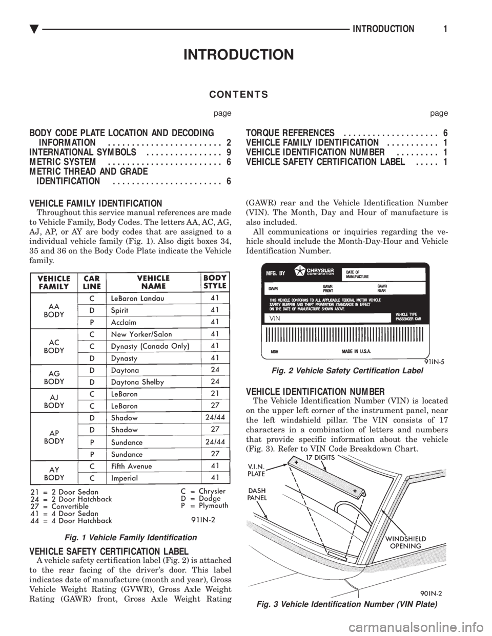
VEHICLE FAMILY IDENTIFICATION
Throughout this service manual references are made
to Vehicle Family, Body Codes. The letters AA, AC, AG,
AJ, AP, or AY are body codes that are assigned to a
individual vehicle family (Fig. 1). Also digit boxes 34,
35 and 36 on the Body Code Plate indicate the Vehicle
family.
VEHICLE SAFETY CERTIFICATION LABEL
A vehicle safety certification label (Fig. 2) is attached
to the rear facing of the driver's door. This label
indicates date of manufacture (month and year), Gross
Vehicle Weight Rating (GVWR), Gross Axle Weight
Rating (GAWR) front, Gross Axle Weight Rating (GAWR) rear and the Vehicle Identification Number
(VIN). The Month, Day and Hour of manufacture is
also included. All communications or inquiries regarding the ve-
hicle should include the Month-Day-Hour and Vehicle
Identification Number.
VEHICLE IDENTIFICATION NUMBER
The Vehicle Identification Number (VIN) is located
on the upper left corner of the instrument panel, near
the left windshield pillar. The VIN consists of 17
characters in a combination of letters and numbers
that provide specific information about the vehicle
(Fig. 3). Refer to VIN Code Breakdown Chart.
Fig. 3 Vehicle Identification Number (VIN Plate)
Fig. 1 Vehicle Family Identification
Fig. 2 Vehicle Safety Certification Label
Ä INTRODUCTION1
Page 2424 of 2438

INTERNATIONAL SYMBOLS
International Symbols are used to identify controls,
displays and indicators. The symbols are used on con-
trols that are displayed on the instrument panel or
in the immediate vicinity of the operator.
INTERNATIONAL SYMBOLS
Ä INTRODUCTION9